Note: Descriptions are shown in the official language in which they were submitted.
208205~
~"~9l/16~8 - PCT/US91/03040
SHOWER CONTROL ASSEMBLY
Backaround of the Invention:
Field of the Invention:
The invention relates to a shower or valve control assembly
for the control of water from a shower head, such as is
commonly used in personal shower baths.
Description of the Related Art:
Methods have been disclosed heretofore for providing such
control. According to U.S. Patent No. 4,651,930, detergent
is aspirated from a bottle through a shower head. In U.S.
Patent No 4,398,668, a shower arm is connected *o existing
hot and cold water ports for varying water temperature and
shutting off water flow from a shower head. U.S. Patent No.
4,729,135 discloses a ~oot-actuated valve for opening and
closing a shower valve with a fluid control and U.S. Patent
No. 2,839,264 similarly relates to a foot-actuated cock for a
shower head. Finally, U.S. Patent No. 2,761,733 relates to a
remote control system for a garden sprinkler. However, all
such systems have disadvantages to be discussed below.
Shower baths are typically eguipped with a spray type shower
head which is supplied with water under pressure from sources
of both hot and cold water. The desired temperature of the
water from the shower head is attained by adjusting the
.
: ~ . ,. '.
W091/1~8 2a820~ ~ PCT/US91/0304~
valves controlling the hot and cold water supplies. These
valves may be separate units or combined into one single
control. The flow rate from the shower head is also regulat-
ed by adjusting the hot and cold water valves or the single
control valve. Some showers are equipped with a flow control
valve at the shower head.
During the act of showering, it is desirable to turn the
water off and on ~requently to conserve water as well as for
personal convenience. It is also a safety feature, espe-
cially for children, to be able to quickly and easily turn
the water off if for any reason it becomes uncomfortable.
Prior to the invention of the instant application, there had
been no convenient way of stopping the flow of water without
necessitating readjustment of the temperature or flow rate or
both when the shower was restarted. When two independent
valves are provided, they must be completely readjusted for
both temperature and flow rate. If a single combined control
is provided, it is too sensitive to be returned to exactly
the desired temperature and flow rate. The single indepen-
dent valve at the shower head can be used to turn the shower
on and off without effecting the temperature adjustment but
lt must be reset to control the flow and it is inconveniently
high, difficult to operate and impossible for children to
~ ~ use. -
.~
::
: .
,
2~8205~
~'~91/16848 3 ~ PCT/US91/03040
It is accordingly an object of the-invention to provide a
shower control assembly, which overcomes the hereinafore-
mentioned disadvantages of the heretofore-known devices of
this general type and which meets the following are objects
of the invention.
l. To provide a shower control which can be used to turn
the shower on and off without affecting the water
temperature adjustments.
2. To provide a shower control for turning the shower
water on and off quickly and at a convenient location.
3. To provide a shower control having means for control-
ling the flow of water which has an adjustment
unaffected by turning the water on or off.
Summary of the Invention:
With the foregoing and other objects in view there is provid- -
; ed, in accordance with the invention, in a shower bath having
a shower head, a hot and cold water supply, and a valving
system for discretely mixing hot and cold water from the
supply for discharge through the shower head, a shower
control assembly comprising a control valve upstream of the
shower head to be switched between an open condition permit-
ting flow and a closed condition preventing flow; and a pilot
vaIve hydraulica}ly connected to the control valve, the pilot
valve being operable in a first position switching the
:
:'
.-
.
.
: - : -
, , .
.
- ,,: ' .: ~,
: .
WO91~16848 2 0 8 2 Q ~ ~ 4 PCT/US91/030~
control valve into the open condition and a second position
switching the control valve into the closed condition, the
pilot valve remaining in one of the first and second posi-
tions without continued application of force.
In accordance with another feature of the invention, the
control valve includes means for adjusting the flow rate of
water through the shower head when the control valve is in
the open condition.
.
In accordance with a further feature of the invention, there
are provided means for mounting the pilot valve on a shower
bath wall.
'~
In accordance with an added feature of the invention, the
control valve includes a diaphragm being selectively movable
between a position permitting flow of water and a position
pre,venting flow of water.
With the objects of the invention in view, there is also
provided a valve control assembly, comprising a control valve
for controlling discharge of water from a pressurized source, -
a valve member movable in the control valve between an open
condltion permitting flow of water and a closed condition
preventing flow of water, and a pilot valve disposed remote
from and connected to the control valve for controlling the
control valve with fluid flowing between the control valve
and the pilot valve, the pilot valve being selectively
, ~ : :
:
`''~91/1~8 5 2 o 8 ~ g5 ~.`i PCT/USg1/03040
operable by external application of force between a first
position moving the valve member into the open condition and
a second position moving the valv~ member into the closed
condition.
In accordance with an additional feature of ~he invention,
the valve member is a diaphragm constructed of an elastomeric
material.
With the objects of the invention in view, there is further-
more provided a valve control assembly, comprising a control
valve having a control valve body with a valve seat, a water
entrance passage upstream of the valve seat, a water exit
passage downstream of the valve seat and a water passage, a
diaphragm between the valve seat and the water passage being
movable away from the valve seat providing an open condition
and toward the valve seat providing a closed condition
between the water entrance and exit passages, a tube commu-
nicating with the water passage, a pilot valve having a pilot
valve body with an entrance port communicating with the tube,
a bore communicating with the entrance port and a valve exit
port communicating with the bore, and a valve spool in the
bore being movable between a first position moving the
diaphragm into the open condition and a second position
moving the diaphragm into the closed condition.
.
In accordance with a concomitant feature of the invention,
there are provided means for manually adjusting the position
. .
.. - . . . .
. . . . ..
WO91/1~ 2 0 8 2 0 S 4 6 PCT/US91/0304Q
of the diaphragm in the open condition, and means for manual-
ly selecting the position of the valve spool.
Control of the flow of water from the shower head is effected
by a pilot and slave valve arrangement wherein the ,slave
valve is in the flow path of the shower head water and is
operated by the pilot valve which is located at any conve-
nient location. The slave valve controls the rate of flow of
water from the shower head without changing the temperature.
Thus the invention includes two separate but cooperating
valves. The main functional valve is located upstream in the
supply conduit to the shower head. This valve is a slave and
is operated by a pilot valve mounted at any convenient
location. The main valve is so constructed that it can be
turned on or off by operation of the pilot valve. The main
valve also has a flow control member which can be adjusted so
that the flow rate returns to the preset amount whenever the
shower is turned on.
Other features which are considered as characteristic for the
invention are set forth in the appended claims.
Although the invention is illustrated and described herein as
embodied in a shower control assembly, it is nevertheless not
intended to be limited to the details shown, since various
modifications and structural changes may be made therein
:. ~ , ~ . ', , .
~ ' ~ ' ' -
.. . . - ..
.. . . . . . - - ..
20820~4 . ~
~91/1~8 7 i PCT/US91/03040
without departing from the spirit of the invention and within
the scope and range of equivalents of the claims.
The construction and method of operation of the invention,
however, together with additional objects and advantages
thereof will be best understood from the following descrip-
tion of specific embodiments when read in connection with the
accompanying drawing.
Brief Description of the Drawina:
Fig. 1 is a fragmentary, diagrammatic, side-elevational view
of the shower control assembly of the invention installed in
a typical tub or shower bath;
Fig. 2 is an enlarged fragmentary, side-elevational view of a
main valve of the assembly;
Fig. 3 is a fragmentary, bottom-plan view of the main valve;
Fig. 4 is a fragmentary, vertical-sectional view of the main
valve in the closed condition:
Fig. 5 is a side-elevational view of the main valve body
taken along the line 5-5 in Fig. 4, in the direction of the
arrows, with all of the other parts removed;
Fig. 6 is a view similar to Fig. 4 showing the main valve in
the open condition:
... . ... : .
... . . . ,: . : . .
2082~5~ `
WO91/16848 . 8 PCT/US91/030
Fig. 7 is a fragmentary, partly broken-away, front-
elevational view of a pilot valve of the assembly;
Fig. 8 is a fragmentary, side-elevational view of the pilot
valve;
Fig. 9 is a fragmentary, vertical-sectional view of the pilot
valve when positioned to stop the flow of water; and
Fig. 10 is a partly vertical-sectional view of the pilot
valve positioned to permit the flow of water.
Description of ~h~e Preferred Embodiment:
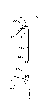
Referring now to the figures of the drawing in detail and
first, particularly, to Fig. 1 thereof, there is seen a
shower control constructed in accordance with a preferred
embodiment of the invention and installed in a typical shower
bath. A main control Ivalve indicated by reference numeral 10
is installed just upstream of a shower head 14 on a supply
pipe 13. The main valve 10, which has a flow control adjust-
in~ knob 18 to be discussed in more detail below, is connect-
ed to a pilot valve 12 by means of a tube 19 and the pilot
valve is mounted on a ~hower wall 20. Water temperature is
controlted by ad~usting one or two valves given reference
numeral 15. Water from the valves 15 normally flows into a
bathtub 16 through a faucet but can be diverted to the shower
head by pulling up on a diverter knob 17 on the faucet which
'
..
~ ... .: ... . - - , : - : .
.
2~820~
~'~91/1~8 9 ' PCT/US91/03040
will remain in the diverting position until pushed down or '
until the valves 15 are turned off.
~he main control valve lO is shown on a larger scale in Fig.
2 and the structure thereof is shown in detail in Fig,. 4. A
valve body 2l is constructed of a rigid material and has
internal threads 22 for attachment to the supply pipe 13
shown in phantom, as well as external threads 23 for attach-
ing the shower head 14 which is also shown in phantom. A ~
water entrance passage 24 terminates in a valve orifice 25. '
A water exit orifice 26 connects into a water exit passage 27
permitting direct flow therefrom into the shower head 14.
.
A valve member in the form of a diaphragm 28 is constructedof an elastomeric material so as to be flexibie and is
located in a counterbore 29 formed in the valve body 21. In
the following description, the upper surface of the diaphragm
28 is understood to be the surface thereof facing the orific- ~ '
es 25 and 26 and upward movement of the diaphragm will be in ~ ''
, , .
the direction toward those orifices. The lower surface and
downward movement i8 understood to be opposite to the upper ~ ''
surfac- and upward movement. A valve bonnet 30 is fitted to ' ,
the counterbore 29 and held in place by screws 31 shown in
Fig. 3. The diaphragm 28 is the valving element and its ,-
operation will be explained below., It also functions as a
gasket to make a pressure tight seal between the valve body
21 and the valv- bonnet 30.
- . :' .
: ~ :
., , . ~ . . ~ . . . , : , . . . -
WO91/1~8 2 ~ 8 2 ~ S 4 10 PCT/US9l/03~4~
A valve seat 32 i5 formed in the valve body 21 at the upper
surface of the diaphragm 28. The valve seat 32 has a shallow
cylindrical relief 32' formed therein in the shape of annular
ring. This is best seen in Fig.5.
The valve bonnet 30 has a threaded bore 33 and a straight
bore 34 formed therein, in which a flow control screw 35 is
rotatably fitted and sealed with an o-ring 36. The flow
control adjusting Xnob 18 is rigidly attached to the flow
control screw 35 by a set screw or other conventional means
which are not shown. A barbed tubing connector 36 is pr2ssed
into the bonnet 30 as means for making a pressure tight
connection with the tube 19. A water passage 38 connects a
space at the lower surface of the diaphragm 28 with the
tubing connector and hence with the tube 19.
The flow control screw 35 has an enlarged diameter portion 39
indicated in Fig. 6, with a serrat,ed upper surface acting as
a limit or stop for downward move=ent of the diaphragm.
Formed onto the upper end of the flow control screw is a
small cylindrical projection.40 which is long enough to pass
through a hole ln the diaphragm. The hole in the diaphragm
through which the projection 40 passes is slightly larger
than the projection thereby permitting water to flow slowly
from the upper ~urface of the diaphragm to the lower surface
of the diaphragm.
-. - . - :
208205~
'`'091/1~8 11 ~ PCT/US91/03040
The structure of the pilot valve 12 is best undPrstood by
describing Figs. 9 and 10, although it is rigidly attached to
the shower wall 20 by means of two suitable screws 41 shown
in Fig. 7 and the outer structure thereof is shown in Fig. 8.
A pilot valve body 42 has a straight valve bore 43 terminat-
ing in a concentric valve stem bore 44 formed therein. A
valve spool 45 is slideable fitted to the bores 43 and 44.
The valve spool 45 is fitted with two O-rings 49 preventing
water leakage from either end of a reduced diameter portion
50 of the valve spool.
A pilot valve operating knob 46 is attached by a screw 47 to
a reduced diameter valve stem 48 and thereby limits the
movement of the valve spool in an inward direction. The
outward motion of the valve spool is limited by a shoulder 51
as shown in Figs. 9 and lO.
.
The pilot valve body 42 has an entrance port 52 into which a
barbed tubing connector 53 is pressed and receives the lower
end of the tube 19. A valve exit port 54 exhausts free to
the at~osphere and a non-iilustrated shower drain.
The operation of the assembly can now be understood and will
be explained below. ;~
The shower is ~tarted with the pilot valve knob 46 in the
first or out position, which permits water flow from the
~. ' .
-
.
W091/1~8 2 0 8 2 0 ~ ~ 12 PCT/USg1/030a~
connecting tube 19 to be discharged through ~he entrance port52, the reduced diameter portion 50 and the valve exit port
45, as seen by the arrows in Fig. 10. The hot and cold water
valve or valves 15 are then turned on and adjusted to produce
the desired water temperature. At this time water will flow
through the supply pipe 13 and into the valve orifice 25. A
very small amount of water flows through the center hole in
the diaphragm 28 around the projection 40. Since the pilot
valve is open, this small amount of water flows readily
through the water passage 38, into the connecting tube 19 and
is discharged. There is accordingly no appreciable pressure
on the lower surface of the diaphragm and it is deflected
downward by the incoming pressure on the upper surface
thereof. Deflection of the diaphragm downward into the open
condition of the diaphragm and therefore of the control valve
when the pilot valve is in the first position, permits free
flow of water through the valve orifice 25, past the valve
seat 32 and into the exit orifice 26, the exi~ passage 27 and
the shower head.
At this time the flow rate of the shower can be adjusted by
turnlng the flow control adjusting knob 18 and limiting the
downward movement of the diaphragm as shown in Fig. 6. This
ad~ustment does not need to be changed for subsequent usage
of the shower.
During the time that the shower is used, when it is desired
to turn the water off, the pilot valve knob 46 can be pushed
~ , . .. . ... .... . . .
: . ., . -, .- . , - - . ~ -
... :- - : ~ - . : . : ~ . . . . ..
~`~91/16~8 13 2 0 8 2 Q 5 4 PCT/US91/03040
to its second or inward position thereby stopping the flow of
water from the lower surface of the diaphragm. In this
closed condition of the diaphragm and the control valve, the
small flow of water through the hole in the diaphragm around
the projection 40 creates pressure on the lower surface of
the diaphragm equal to the incoming pressure at the valve
orifice 25. Since the pressure on the upper surface of the
diaphragm in the area outside the valve seat 32 is reduced by
reason of the flow past the valve seat, this creates an
imbalance of forces on the diaphragm causing it to move
upward and stop the flow of water as shown in Fig. 4. In
order to restart the flow of water, the pilot valve knob can
be pulled out and flow will be at the rate and temperature !
previously set.
Modifications to the present invention will be apparent to
those skilled in the art, therefore no limitation to the
invention is intended by way of the description and the
accompanying drawings.
.
'.
~'' ' ~ '.
'
,
. . . ..
,