Language selection

Search

Patent 2082147 Summary

Third-party information liability

Some of the information on this Web page has been provided by external sources. The Government of Canada is not responsible for the accuracy, reliability or currency of the information supplied by external sources. Users wishing to rely upon this information should consult directly with the source of the information. Content provided by external sources is not subject to official languages, privacy and accessibility requirements.

Claims and Abstract availability

Any discrepancies in the text and image of the Claims and Abstract are due to differing posting times. Text of the Claims and Abstract are posted:

  • At the time the application is open to public inspection;
  • At the time of issue of the patent (grant).
(12) Patent Application: (11) CA 2082147
(54) English Title: MELTING FURNACE FOR THE MELTING OF MINERAL FIBRE RAW MATERIAL
(54) French Title: FOUR DE FUSION POUR MATERIAUX AMORPHES A BASE DE FIBRE MINERALE
Status: Deemed Abandoned and Beyond the Period of Reinstatement - Pending Response to Notice of Disregarded Communication
Bibliographic Data
(51) International Patent Classification (IPC):
  • C03B 05/26 (2006.01)
  • F27D 03/14 (2006.01)
(72) Inventors :
  • SOLIN, PETER A. H. (Finland)
  • HJERPPE, PERTTI K. (Finland)
  • NYGARDAS, CARL-GUSTAV (Finland)
(73) Owners :
  • PAROC OY AB
(71) Applicants :
  • PAROC OY AB (Finland)
(74) Agent: MCCARTHY TETRAULT LLP
(74) Associate agent:
(45) Issued:
(86) PCT Filing Date: 1991-05-02
(87) Open to Public Inspection: 1991-11-05
Availability of licence: N/A
Dedicated to the Public: N/A
(25) Language of filing: English

Patent Cooperation Treaty (PCT): Yes
(86) PCT Filing Number: PCT/FI1991/000127
(87) International Publication Number: FI1991000127
(85) National Entry: 1992-11-04

(30) Application Priority Data:
Application No. Country/Territory Date
902235 (Finland) 1990-05-04

Abstracts

English Abstract

2082147 9117125 PCTABS00008
The invention concerns a melting furnace for the melting of
mineral fibre raw material which furnace comprises a bottom part (1),
sidewalls (2) and a cover (3), and supply means for the raw
material. The melting furnace is provided with a discharge opening (4)
in the sidewall (2) for mineral melt (8) at a distance from the
bottom part (2) of the melting furnace, and a discharge opening
(6) for emptying the melting furnace, at the level of the bottom
part (2). The melting furnace further comprises an additional
discharge opening (7) for discharging of iron melt (11) formed during
the melting process provided in the sidewall (2) at a level
above the discharge opening (6) for emptying the melting furnace, but
at a level below the discharge opening (4) for the mineral melt
(8).


Claims

Note: Claims are shown in the official language in which they were submitted.

WO 91/17125 PCT/FI91/00127
Claims
1. Melting furnace for the melting of mineral fibre raw
material which furnace comprises a bottom part (1), side
walls (2) and a cover (3), supply means for the raw
material, as well as a discharge opening (4) in the side
wall (2) for mineral melt (8) at a distance from the bottom
part (2) of the melting furnace, and a discharge opening
(6) for emptying the melting furnace, at the level of the
bottom part (2), characterized in that an additional
discharge opening (7) for discharging of iron melt (11)
formed during the melting process is provided in the side
wall (2) at a level above the discharge opening (6) for
emptying the melting furnace, but at a level below the
discharge opening (4) for the mineral melt (8).
2. Melting furnace according to the Claim 1, characterized
in that the two lower discharge openings (6, 7) are
arranged in a common block.
3. Melting furnace according to the Claim 2, characterized
in that the two lower discharge openings (6, 7) are
normally closed and are opened by drilling and/or burning
with oxygen.
4. Melting furnace according to the Claim 3, characterized
in that the discharge opening (7) for iron melt (11) is
closed with a mud gun.
5. Melting furnace according to the Claim 2, characterized
in that the block is a carbon block divided into four parts
the two outermost parts being replacable.
6. Melting furnace according to the Claim 5, characterized
in that the block on the inside of the furnace is protected
with a lining mix (10).

Description

Note: Descriptions are shown in the official language in which they were submitted.


W~)91/17t25 1 S'Cr/FI')1/00127
~'
Melting furnace ~or the meltil)g of mineral fibre raw
material
This invention concerns a melting furnace for the melting
o mineral fibre raw material, the furnace~comprisiny a
bottom part, side walls and a cover, supply means ~or the
raw materlal, as well as a discharge opening in the side
wall for mineral melt arranged a-t a distance from thé
bottom part of the melting furnace, and a discharge opening
for emptying the melting furnace, at the level of the
bottom part.
Mineral wool products of glass wool, rock wool and slag
wool type are the most well known and used products for
both heat and acoustical insulation.
These products are made e.g. so that the raw material, such
as rock mineral or slag rom iron production, are melted in
a melting furnace. Mineral melt is withdrawn continuously
from the furnace and converted to fibres e.g. in a spinning
unit consisting of a plurality of rotating wheels, from
which the mineral melt is spun under the formation of
fibres. The thus formed fibres are transported with an air
current from the spinning unit and collected onto a
conveyor in the form of a fibre felt. The fibre felt is
then subjected to further processing steps, e.g. impregna-
tion with a binder, such as a resin, which in a final stage
of the manufacturing proce~s is cured, e.g. in a curing
-- -oven. During curing the fibres are'fixed to -each other-
forming a form stable felt of the desired density and
thickness. The c,ured ibre felt can thereafter e.g. be cut
to the desired shape, such as sheet products or roll
products, which thereafter are packed or processed further.
During the melting process, the iron oxide, or part
. ~ ; .
. .

W091/171~ 2 0 8 ~
thereof, contained in the mineral raw material or the slag
is reduced to metalllc lron and sinks to the bottom of the
furnace in the form of an iron melt, whlch continuously
increases in volume. In order to prevent iron melt from
accompanying mineral melt in to t;he spinning unit, the iron
melt has to be removed at regular intervals from the
melting furnace. In the prior 3cnown melting furnaces the
iron melt is removed through a discharge opening in the
bottom of the melting furnace, whereby the iron melt is
completely removed at each emptying operation. This method
cf proceeding is used e.g. in the melting furnace according
the FI-patent application no 853458.
The mineral melt formed during the melting process has a
very corrosive effect on the walls of the melting furnace.
This results in the fact that the melting furnace on its
inside has to be provided with an extremely corrosion
resistant lining, which is both e~pensive and difficult to
apply.
Tests made have shown that the iron melt which collects at
the bottom of the melting furnace has a much gentler effect
on the lining than the mineral melt. If it is possible -to
prevent the iron melt from sinking below a predetermined
level, it is possible to use in the bottom part of the
melting furnace a much cheaper lining. This is achieved in
the melting furnace according to the present invention by
providing an additional discharge opening for discharging
iron melt formed in the melting process, in the side wall
at a level above the dlscharge opening for emptying the
melting furnace, but at a level below the discharge opening
for the mineral meltO With this solutlon the level of the
iron melt is prevented from sinking below the level of the
additional discharge opening. In order to ensure that the
bottom part of the melting furnace as soon as possible
after starting up the furnace is covered by a protective
layer of iron melt, pig iron is added to the melting
.
, '. '
,

WO91/1712~ ` ~ 208 21~ 7 P~r/FI~Jl/(Jol27
furnace prior to starting the introduction of rock raw
material.
The other characteristics of the invention appear from the
appended Claims 1 to 6.
In the following the inventlon will be described in more
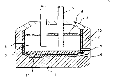
detail referring to the drawing which shows schematically
an esample of a melting furnace according to the invention~
The melting furnace comprises a bottom part 1, side walls
2 and a cover 3. A number of electrode rods 5, preferably
of graphite, extend through the covex by means of which the
raw material 9 is melted. I'his raw material 9 is introduced
into the melting furnace by means of supply means (not
shown ), which are arranged to distribute the rock raw
material 9 in a substantially even layer over the mineral
melt 8 formed during the melting process. Mineral melt 8 is
withdrawn during the melting process in a constant flo~
from the melting furnace through a discharge opening 4
arranged in the side wall 2 to a spinning device (not
shown) for the formation of mineral fibres. The discharge
opening 4 is situated at a level at a distance from the
bottom part 2 of the melting furnare. For emptying purposes
the melting furnace is provided with a discharge opening 6
at the level of the bottom part 2. Above the discharge
opening 6, there is arranged in the side wall 2 an addi-
tional discharge opening 7 for discharging iron melt 11
formed during the melting process. This additional dischar-
ge opening 7 is situated at a level lower than the dischar~
ge opening 4 for the mineral melt 8.
The two lower discharge openings 6 and 7 are suitably
arranged in a common block, which according to a preferred
embodiment is a carbon block divided into four parts, where
the two outer parts, in which the respective discharge
openings 6 and 7 are arranged, are replacable. The inside
.. ..
.. . , :
,

WO')1tl7125 : `~ . 2~) 8 2 ~ P~l1/FI~I/00l~7
of the block is preferably covered with a lining mix 10.
During the melting process some of the iron oxide in the
raw material 9 is reduced to metallic iron which sinks to
the bottom of the melting ~urnace and results in a steady
increase of the amount of iron melt 11. The discharge
openings 6 and 7 are normally closed and are opened only
when necessary. In order to prevent the level of the iron
melt from reaching the openin~ 4 for the mineral melt,
excess iron melt has to be removed at regular intervalsO
Normally excess iron melt 11 is removed from the rnelting
furnace at about 2 to 3 months intervals. The discharge
opening 7 is then opened using a drilling machine or by
burning with oxygen. When the desired quantity of iron melt
11 has been withdrawn from the furnace, the discharge
opening 7 is closed using a mud gun (not shown) which has
been precharged with heated sealing mud. The drawing shows
the state when all excess iron melt has been removed. The
discharge opening 6 is opened only when the whole melting
furnace is to be emptied, e.g. for service or for renewing
the lining. Opening of the discharge opening 6 takes most
conveniently place by burning with oxygen.
.
, ~ - . .
. .
I

Representative Drawing
A single figure which represents the drawing illustrating the invention.
Administrative Status

2024-08-01:As part of the Next Generation Patents (NGP) transition, the Canadian Patents Database (CPD) now contains a more detailed Event History, which replicates the Event Log of our new back-office solution.

Please note that "Inactive:" events refers to events no longer in use in our new back-office solution.

For a clearer understanding of the status of the application/patent presented on this page, the site Disclaimer , as well as the definitions for Patent , Event History , Maintenance Fee  and Payment History  should be consulted.

Event History

Description Date
Time Limit for Reversal Expired 1994-11-02
Application Not Reinstated by Deadline 1994-11-02
Deemed Abandoned - Failure to Respond to Maintenance Fee Notice 1994-05-02
Inactive: Adhoc Request Documented 1994-05-02
Application Published (Open to Public Inspection) 1991-11-05

Abandonment History

Abandonment Date Reason Reinstatement Date
1994-05-02
Owners on Record

Note: Records showing the ownership history in alphabetical order.

Current Owners on Record
PAROC OY AB
Past Owners on Record
CARL-GUSTAV NYGARDAS
PERTTI K. HJERPPE
PETER A. H. SOLIN
Past Owners that do not appear in the "Owners on Record" listing will appear in other documentation within the application.
Documents

To view selected files, please enter reCAPTCHA code :


To view images, click a link in the Document Description column. To download the documents, select one or more checkboxes in the first column and then click the "Download Selected in PDF format (Zip Archive)" or the "Download Selected as Single PDF" button.

List of published and non-published patent-specific documents on the CPD .

If you have any difficulty accessing content, you can call the Client Service Centre at 1-866-997-1936 or send them an e-mail at CIPO Client Service Centre.


Document
Description 
Date
(yyyy-mm-dd) 
Number of pages   Size of Image (KB) 
Abstract 1991-11-04 1 52
Claims 1991-11-04 1 38
Drawings 1991-11-04 1 14
Abstract 1991-11-04 1 74
Descriptions 1991-11-04 4 168
Representative drawing 1999-01-18 1 15
Fees 1992-11-03 1 39
International preliminary examination report 1992-11-03 8 145