Language selection

Search

Patent 2082150 Summary

Third-party information liability

Some of the information on this Web page has been provided by external sources. The Government of Canada is not responsible for the accuracy, reliability or currency of the information supplied by external sources. Users wishing to rely upon this information should consult directly with the source of the information. Content provided by external sources is not subject to official languages, privacy and accessibility requirements.

Claims and Abstract availability

Any discrepancies in the text and image of the Claims and Abstract are due to differing posting times. Text of the Claims and Abstract are posted:

  • At the time the application is open to public inspection;
  • At the time of issue of the patent (grant).
(12) Patent Application: (11) CA 2082150
(54) English Title: VEHICLE BRAKE WITH BRAKE CYLINDER BORE INSERT
(54) French Title: FREIN DE VEHICULE AVEC RACCORD D'ETANCHEITE INSERE DANS L'ALESAGE DU CYLINDRE
Status: Deemed Abandoned and Beyond the Period of Reinstatement - Pending Response to Notice of Disregarded Communication
Bibliographic Data
(51) International Patent Classification (IPC):
  • F16D 65/16 (2006.01)
  • F16D 55/02 (2006.01)
  • F16D 65/14 (2006.01)
  • F16D 65/18 (2006.01)
(72) Inventors :
  • TEMPLE, ROBERT BRUCE (United States of America)
  • BEHRMANN, EDGAR ANTHONY (United States of America)
  • JOHANNESEN, DONALD DIXON (United States of America)
(73) Owners :
  • ROBERT BOSCH TECHNOLOGY CORPORATION
(71) Applicants :
(74) Agent: MACRAE & CO.
(74) Associate agent:
(45) Issued:
(86) PCT Filing Date: 1991-05-09
(87) Open to Public Inspection: 1991-12-22
Availability of licence: N/A
Dedicated to the Public: N/A
(25) Language of filing: English

Patent Cooperation Treaty (PCT): Yes
(86) PCT Filing Number: PCT/US1991/003219
(87) International Publication Number: WO 1991019912
(85) National Entry: 1992-11-04

(30) Application Priority Data:
Application No. Country/Territory Date
541,680 (United States of America) 1990-06-21

Abstracts

English Abstract

2082150 9119912 PCTABS00008
The vehicle brake with brake cylinder bore insert (30, 130)
comprises a cast disc brake cylinder (12, 112) which includes a bore
(14, 114) into which the bore insert (30, 130) may be disposed.
The bore (14, 114) may have an opening (22, 118) at either one (20,
120) of the opposite axial ends for inserting the bore insert
(30, 130). The insert has lock ribs (34) disposed about the
perimeter (32) thereof, and at opposite axial ends a pair of perimeter
extensions or crush ribs (36) which tightly engage the surface
(21, 121) of the bore (14, 114) when the insert (30, 130) is
disposed within the bore (14, 114). The insert (30, 130) has opposite
flat sides (50) which permit an adhesive material to be disposed
between the lock ribs (34) and the surface (21, 121) of the bore
(14) in order to fix the insert (30) within the bore (14). The
insert (30, 130) contains a central opening (39, 139) which may be of
different diameters or shapes for receiving a piston (40) and
seals disposed about the piston (40).


Claims

Note: Claims are shown in the official language in which they were submitted.

WO 91/19912 PCT/US91/03219
- 5 -
A VEHICLE BRAKE WITH BRAKE CYLINDER BORE INSERT
CLAIMS
1. A vehicle brake with a brake cylinder (10)
having a bore insert (30), comprising an interior cavity
(14) of the brake cylinder (10) being a bore (14) for
receiving therein the bore insert (30), brake fluid, and
piston means (40), the bore (14) communicating with at
least one opening (18) in the cylinder (10) for receiving
the brake fluid and a large opening (22) receiving said
piston means (40), the bore insert (30) comprising an
outer perimeter (32) with perimeter extensions (36)
extending beyond the outer perimeter (32) at opposite
axial ends of the insert (30), and a central opening (39)
therein, the bore insert (30) disposed within the bore
(14) such that the perimeter extensions (36) are tightly
engaged by the surface of the bore (14) and the piston
means (40) received slidably within the central opening
(39) of the bore insert (30).
2. The brake in accordance with Claim 1, wherein
the insert (30) comprises a plurality of rib means (34)
disposed about the outer perimeter (32) thereof.
3. The brake in accordance with Claim 2, wherein
one axial end (35) of the insert comprises crush rings
(38) thereat, and the bore (14) comprises a stepped bore
(14) having a shoulder (15) which is engaged by said
crush rings (38).
4. The brake in accordance with Claim 2, wherein
the perimeter extensions (36) of the bore insert comprise
crush rib means (36).
5. The brake in accordance with Claim 4, wherein
the brake comprises a disc brake and the bore insert (30)
includes about the central opening (39) groove means (46)
for receiving seal means (48).
6. The brake in accordance with Claim 5, wherein
the seal means is disposed between the bore insert (30)
and piston means (40).

WO 91/19912 PCT/US91/03219
- 6 -
7. The brake in accordance with Claim 6, wherein
the bore insert (30) comprises oppositely disposed flat
sides (50).
8. the brake in accordance with Claim 7, wherein
adhesive means is disposed between the surface of the
bore (14) and flat sides (50) of the bore insert (30)
such that the adhesive is between said rib means (34) of
the outer perimeter (32) and the bore (14) in order to
fix the bore insert (30) in engagement with the brake
cylinder (10).
9. The brake in accordance with Claim 6,
wherein the bore (14) comprises a reduced diameter
portion (17) providing a shoulder (15) of the bore (14)
and defining said large opening (22) through which the
piston means (40) extends, the bore insert (30) abutting
said shoulder (15).
10. The brake in accordance with Claim 9,
wherein the bore (114) includes at one end an opening
(118) through which said insert (130) is inserted and
positioned within the bore (114).

Description

Note: Descriptions are shown in the official language in which they were submitted.


2 Q 8 .~
WO91/19s12 PCT/US91/03219
A VEHICLE BRARE WITH BRAKE CYLINDER BORE INSERT
The present invention relates generally to abrake cylinder having a bore insert, and in particular to
a disc brake having a bore insert with variable size
piston openings.
Disc brake cylinders are typically made from
castings that must be machined in order to receive other
component parts. The bore of the cylinder must be
machined so that it will receive slidably the piston, and
so that one or more grooves therein will house a seal
that sealingly engages the surface of the piston and
house a boot seal which estends between the bore and
piston in order to keep contaminants out of the bore.
This machining requires manufacturing time and increases
the cost of the brake. Additionally, different size
brakes require different castings in order to accommodate
the different diameter pistons. It is highly desirable
to oliminate the machining typically required or a disc
brako cylinder, and particularly for a cylinder housed in
the caliper of the brake, and it would b~ estremely advan-
tageous to provide a aisc brake cylinder which would
Jerve as a common cylinder for various size pistons. The
eliminat~on of machining would greatly reduce the cost
and complesity of providing the caliper housing, and the
25 provision of a common cast cylinder for various size
brakes would also greatly reduce manufacturing time and
cost.
The present invention solves the above problems
by providing a vehicle brake with a brake cylinder having
30 a bore insert, comprising a brake cylinder having an inte-
rior cavity comprising a bore for receiving therein a
bore insert, brake 1uid, and piston means, the bore com-
municating with at least one opening in the cylinder for
receiving the brake fluid and a large opening receiving
35 sa~d piston means, the-bore insert comprising a member
having an outer perimeter with perimeter e~tensions
e~tending beyond the outer perimeter at opposite a~ial
, . . .
. . .
. . ~ ,

WO91/1g912 32 ~ 5~ PCT/US91/03219
ends of the bore insert, and a central opening therein,
the bore insert disposed within the bore such that the
perimeter estensions are tightly engage`d by the surface
of the bore, and the piston means received slidably
within the central opening of the bore insert.
The present invention is described in detail
below with reference to the drawings which illustrate
embodiments in which:
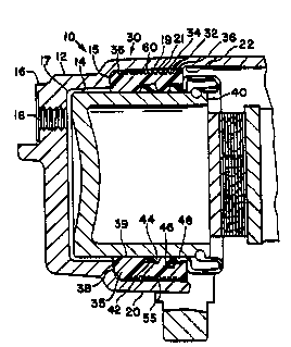
Figure l is an illustration of a disc brake
cylinder having a bore insert;
Figure 2 is a side view of the bore insert of
Figure l;
Figure 3 is a section view of the bore insert of
l5 Figure 2;
Figure 4 is an end view of the bore insert; and
Figure 5 is an alternative embodiment of a disc
brake caliper housing having a bore insert of the present
invention.
A brake cylinder ha~ing the bore insort of the
20 present invention i8 illustratod in Pigure l. ~rake
cylind-r l0 comprises a cast cylinder 12 which tefines an
interior opening or ~tepped bore 14. One end 16 of cyl-
inder 12 includes an opening l~ for receiving brake
flu~d. The opposite end 20 of cylinder 12 includes a
25large opening 22 for receiving a bore insert indicated
generally by reference numeral 30, and a piston 40.
Stepped bore 14 includes a shoulder 15 between a reduced
diameter section 17 and a large diimeter section l9.
Cylinder 12 may be cast in just one standard size for all
30 8ize8 of disc brake constructions, because insert 30 may
have various size openings therein in order to accommo-
date d~fferent size pistons 40. Insert 30 comprises a
generally annular, nonannular, or noncircular member,
depending on the shape of the large diameter section l9,
35and includes an outer perimeter 32 having lock ribs 34
thereabout. Insert 30 further includes at opposite a~ial
ends perimeter extensions or crush ribs 36 which are
.

~;8~
WO91/19912 PCT/US91/03219
-- 3 --
slightly larger than opening 22 of the large diameter
section 19 so as to effect a tight interference fit there-
between. Axial end 35 of bore insert 30 includes there-
about asial crush rings 38 for engagement with bore
shoulder 15. Bore insert 30 includes a central opening
39 which includes therein a groove 42 for receiving a
typical piston seal 44 and an outer groove 46 for receiv-
ing one end of a typical boot seal 48 or a wiper type
seal which estends between bore insert 30 and piston 40.
Piston 40 may be a metallic or phenolic piston which
slidably engaqes central opening 39, whereby piston seal
44 prevents brake fluid from escaping from stepped bore
14.
~ ore insert 30 includes opposite flat sides 50
(see Figures 2 and 4) which enable insert 30 to be fisedly
attached in stepped bore 14 such that pressurized brake
fluid will not force insert 30 from bore 14. An adhesive
material such as an opo~y 55 would be inserted between
flat s~des 50 and surface 21 of large diameter section 19
20 60 that the adhesive material enters area 60 disposed
between lock ribs 34 and surface 21. The adhesive would,
via the lock ribs and the natural as-cast rough surface
of large diamater section'l9, adhero boro insert 30 to
bore 14.
,Bore insert 30 could be provided by a number of
materials. Such materials could comprise injection
molded high performance thermao-plastics such as a liquid
crystal polymer e~emplified by Amoco's Xydar R and poly-
phenylenesulfide (~PPS~) e~emplified by General Electric's
30Supoc 401 and Phillips Ryton 4, as well as Allied Chemical
products such as Phenolic-Triazine copolymer thermoset
plastics. Also, compression molded phenolic composites
such as Darez 29502, cast or molded ceramics, or injection
molded rubbers could be used.
A disc brake with the bore insert of the present
invention is provided by inserting an appropriately sized
bore insert within the bore 14 to effect a press fit
- ' , ~ '
. ~ . " . ............................ . .
.: , ', . ; ~ ' . .

WO91/19912 2 B ~ 21~ ~ PCT/US91/03219
-- 4
between crush ribs 36 and large diameter section 19, and
a similar fit between axial crush rings 38 and shoulder
15. Then the adhesive material is inserted into area 60
between the large diameter section 19 of bore 14 and the
5 flat sides 50 of bore insert 30 so that the adhesive
material fixedly adheres the bore insert within bore 14.
This would provide a strong mechanical lock between bore
insert 30 and cylinder 12. If necessary, more prominent
or radially extending features could be cast on surface
10 21 of the bore 14 in order to provide a stronger lock via
the adhesive material.
Figure 5 illustrates an alternative embodiment
of the present invention wherein a disc brake caliper
housing 110 comprises a brake cylinder 112 having a bore
15 114 with an a~ial opening 122 disposed oppositely from an
asial opening 118. Opening 118 would be closed by
another member fixed to that end of housing 110. A bore
in~ert 130, which is similar to the insert in the pre-
vious embodiment, would be inserted via opening 118 and
20 abut the bore ~houlder 115 which defines a~ial opening
122 at end 116. This embodiment of the invention would
enJuro th~t the bore insert could not be forced from bore
114 by pre8surized brake fluid. Adhesive material could
be utilized to retain bore insert 130 at its position
25ad~acent opening 122 and to provide a hydraulic seal
between the insert and housing. Shoulder 115 would define
with groove 146 an outer retention groove for one end of
a flexible boot seal ~not shown).
;. ~. .
. '

Representative Drawing
A single figure which represents the drawing illustrating the invention.
Administrative Status

2024-08-01:As part of the Next Generation Patents (NGP) transition, the Canadian Patents Database (CPD) now contains a more detailed Event History, which replicates the Event Log of our new back-office solution.

Please note that "Inactive:" events refers to events no longer in use in our new back-office solution.

For a clearer understanding of the status of the application/patent presented on this page, the site Disclaimer , as well as the definitions for Patent , Event History , Maintenance Fee  and Payment History  should be consulted.

Event History

Description Date
Inactive: IPC deactivated 2012-01-07
Inactive: IPC expired 2012-01-01
Inactive: IPC from PCS 2012-01-01
Inactive: IPC from MCD 2006-03-11
Inactive: Dead - RFE never made 1999-05-10
Deemed Abandoned - Failure to Respond to Maintenance Fee Notice 1999-05-10
Application Not Reinstated by Deadline 1999-05-10
Inactive: Abandon-RFE+Late fee unpaid-Correspondence sent 1998-05-11
Application Published (Open to Public Inspection) 1991-12-22

Abandonment History

Abandonment Date Reason Reinstatement Date
1999-05-10

Maintenance Fee

The last payment was received on 

Note : If the full payment has not been received on or before the date indicated, a further fee may be required which may be one of the following

  • the reinstatement fee;
  • the late payment fee; or
  • additional fee to reverse deemed expiry.

Please refer to the CIPO Patent Fees web page to see all current fee amounts.

Fee History

Fee Type Anniversary Year Due Date Paid Date
MF (application, 7th anniv.) - standard 07 1998-05-11 1998-02-19
MF (application, 2nd anniv.) - standard 02 1993-05-10
Owners on Record

Note: Records showing the ownership history in alphabetical order.

Current Owners on Record
ROBERT BOSCH TECHNOLOGY CORPORATION
Past Owners on Record
DONALD DIXON JOHANNESEN
EDGAR ANTHONY BEHRMANN
ROBERT BRUCE TEMPLE
Past Owners that do not appear in the "Owners on Record" listing will appear in other documentation within the application.
Documents

To view selected files, please enter reCAPTCHA code :


To view images, click a link in the Document Description column. To download the documents, select one or more checkboxes in the first column and then click the "Download Selected in PDF format (Zip Archive)" or the "Download Selected as Single PDF" button.

List of published and non-published patent-specific documents on the CPD .

If you have any difficulty accessing content, you can call the Client Service Centre at 1-866-997-1936 or send them an e-mail at CIPO Client Service Centre.


Document
Description 
Date
(yyyy-mm-dd) 
Number of pages   Size of Image (KB) 
Abstract 1991-12-22 1 54
Cover Page 1991-12-22 1 14
Claims 1991-12-22 2 61
Drawings 1991-12-22 2 36
Abstract 1991-12-22 1 71
Descriptions 1991-12-22 4 153
Representative drawing 1999-01-19 1 12
Reminder - Request for Examination 1998-01-21 1 117
Courtesy - Abandonment Letter (Request for Examination) 1998-06-22 1 171
Courtesy - Abandonment Letter (Maintenance Fee) 1999-06-07 1 186
Fees 1997-04-09 1 52
Fees 1996-03-29 1 67
Fees 1995-03-29 1 74
Fees 1994-04-28 1 72
Fees 1992-11-04 1 44
International preliminary examination report 1992-11-04 9 269
PCT Correspondence 1993-02-16 1 28