Note: Descriptions are shown in the official language in which they were submitted.
CY
SHEET FLOW SPOUT
Field of the Invention
The invention relates to spouts that provide a stream
of water in the form of a sheet. This design is
particularly suited to a shower nozzle or the like.
Backctround of the Art
The pleasing esthetic qualities of water flowing in a
sheet are well recognized and certain types of spouts for
producing these sheets are known. In one type of "sheet
flow spout" such as that of U.S. Patent 4,334,328, a narrow
slot is formed having a cross-section matching that of the
desired sheet of water. A flow chamber between the water
supply and the narrow slot smooths the flow of the water so
that when it exits the narrow slot, it continues as a sheet
for a distance. Producing a wide sheet of water with such a
design, using practical rates of water flow, requires that
the slot be narrow. Manufacturing a narrow slot is
difficult and such a narrow slot may be difficult to clean
or susceptible to clogging.
In a second type of sheet flow spout, the narrow slot
is replaced by a single deflector which is impinged by a
stream of water from a nozzle. The water spreads upon
impact with the deflector to form the sheet. This spreading
_2.
of the water as it strikes the deflector also limits the
free length of the sheet before it breaks up into
droplets. This is because the thinning of the expanding
sheet soon exceeds the limits of surface tension of the
water holding the sheet together.
This problem of the diverging sheet thinning too
quickly may, to some extent, be overcome by the use of
multiple jets, each of which "shepherds" a neighboring
jet to prevent the excessive spreading of the water after
it leaves the deflector. See eTa. Patent 4,912,782.
Unfortunately, the use of multiple jets may produce
a sheet of uneven thickness and, in any event, may be
costly.
The present invention provides a spout, comprising a
nozzle for accepting a flow of water from a water supply
and conducting it along a nozzle axis to a nozzle
discharge orifice; and a shield having a curved surface
overlying the orifice that is fixed relative to the
orifice, the surface having a face portion spaced from
and opposing the orifice to create a slot between the
shield and orifice for forming the water into a sheet;
and a guide portion extending about the face portion in
two orthogonal directions and having an outer edge lower
than the face portion, the guide portion having a
curvature inward toward the orifice in the two orthogonal
directions for deflecting the sheet inward before the
sheet passes the outer edge to promote the formation of a
continuous sheet of water suitable in which to bathe.
.. . ,.
In accordance with the invention, the sheet of water
issuing from the spout remains continuous over an
extended length as it falls without the use of a narrow
slot or multiple jets. The guide being curved in two
dimensions (e. g. spherical) provides both a sheet forming
and sheet smoothing typically performed by a narrow slot.
The dual curvature of the shield also serves to focus the
sheet along an axis to prolong the free length of the
sheet without the need for multiple jets.
The nozzle may be non-circular in cross-section to
provide substantially greater water flow off of the
nozzle axis. The path between the rim and the face
portion opposite the predominate water flow along the
nozzle axis may be blocked by a wall.
The invention provides the benefits of a "slot type"
sheet flow spout and of "multiple jet" type sheet flow
spout but with a single nozzle and shield arrangement.
The shield has an outer edge with a face which may be
formed to have a tapered sharp edge. The sharp edge
reduces the attachment of the water to the deflecting
surface. The sheet of water issuing from the spout has
reduced divergence.
Other features and advantages besides those
discussed above will be apparent to those skilled in the
art from the description of the preferred embodiment of
the invention which follows. Thus, in the description,
reference is made to the accompanying drawings, which
form a part hereof, and which illustrate one example of
the invention. Such
........_-_..__..,-..-..~..__~~... ._....__.__.-_.~._~..,.._.... . . ........-
~..~~~..._.....
~(~~~~'
example, however, is not' exhaustive of the various
alternative forms of the invention. Therefore, reference
should be made to the claims which follow the description
for determining the full scope of the invention.
Brief Description of the Drawings
Fig. 1 is a side elevational view of the sheet flow
spout of the present invention, showing a sheet of water
extending therefrom;
Fig. 2 is a view similar to that of Fig. 1 but in
cross-section, the cross section being taken through the
midline of the sheet flow spout of Fig. 1 along the plane of
the paper;
Fig. 3 is a cross-sectional view similar to that of
Fig. 2 with the cross-sectional plane displaced from the
midline, but parallel to that of Fig. 2;
Fig. 4 is a cross-sectional view, along the line 4-4 of
Fig. 2;
Fig. 5 is a perspective, exploded view of the two main
pieces of the sheet flow spout of Fig. 1;
Fig. 6 is a schematic view similar to Fig. 2 showing
the radius and center of a theoretical sphere of which the
shield is a part;
Fig. 7 is a detail of the shield and nozzle in cross-
section, along line 7-7 in Fig. 2, showing the focusing of
the streams of water caused by the gradients of curvature of
the shield; and
-4-
. ........o _._..._..~..-..,~._~.,-..,..~,..,~,~...~ _. ._...,.~.. . ~~..~
~..~ _ ~_ ._..__ .~_,_ . _.....
2~~~~
Fig. 8 is a detail'of Fig. 4 showing the forces acting
on unequal thicknesses of the sheet passing along the
shield.
Description of the Preferred Embodiment
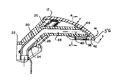
Referring to Fig. 1, the sheet flow spout 10 of the
present invention comprises generally a curved shield 12
having an inner surface conforming to a part of a sphere.
The shield 12 has a lower edge 14 from which issues a sheet
of water I6 extending in air for a free length 17 prior to
breaking into droplets 18. The upper edge of the shield 12
attaches to a nozzle assembly 20 which preferably extends
upward from a collar 22 attached to a shower assembly (not
shown) at head height within a shower stall.
Referring to Fig. 3, the shield 12 is attached to the
nozzle assembly 20 by means of threaded bosses 30 extending
from and attached to the lower surface of the shield 12.
When the shield is attached to the nozzle assembly 20, the
threaded bosses 30 fit into a cavity 32 within the upper end
of nozzle assembly 20.
Bolts 34 pass upward through the collar 22 and through
bores in the nozzle assembly 20 to be received by the
threaded bosses 30 and to be tightened so as to pull the
shield 12 firmly against the nozzle assembly 20, the latter
sandwiched between the collar 22 and the threaded bosses 30
of the shield 12. The head of the bolts 34 also captures a
flange 36 against the lower side of the collar 22, such
-5-
flange 36 aiding in mounting the sheet flow spout 10 to the
supporting shower assembly.
As shown in Fig. 2, the nozzle assembly 20 incorporates
a central inlet coupling 24 for receiving water through the
collar 22 from water supply lines (not shown) and for
passing that water to a channel 26 within the nozzle
assembly 20, and then ultimately to a generally horizontally
disposed nozzle 28. Nozzle 28 terminates at an orifice 38
cut at an oblique angle to the generally horizontal axis 40
of the noz$le 28. The angle of the orifice 38 is such as to
conform generally to~a lower, inner surface of the shield 12
and to be spaced somewhat from that surface to create a slot
42 between the orifice 38 and the lower surface of the
shield 12. .
As a result of the geometry of the shield 12 and the
interaction between the shield and the nozzle 28, as will be
described, the slot 42 may be substantially wider than the
thickness of the sheet 16 ultimately produced by the spout
10. This thickness of the slot 42 reduces the chance of the
slot 42 clogging, as compared to designs employing a much
narrower sheet-forming slot.
Referring to'Fig. 5, a wall ridge 44 attached to the
upper rim 38 and abutting the lower surface of shield 12
prevents the flow of Water from the nozzle 28 upward along
shield 12 toward the rear of the nozzle assembly 20 thus
providing the limits to the angular extent of the slot 42
being approximately 180° around the nozzle axis 40.
-6-
_..... ..~ ..w .... _ . ...~~....~..~ ~...,. . . _....~W ~_ _W._ ~_ ..~_.~.
_... .
~;~ ~.t ~~ ~7
Referring now to Fig. 7, water exiting the nozzle 28
from the slot 42 may proceed between orthogonal axes 46 and
48, the latter generally being along to axis 40 of the
nozzle 28. Water may exit in a forward direction along axis
48 but not in the backward direction as a result of the wall
ridge 44. Water may also exit the nozzle 28 along axis 46
in the left or right direction.
Referring now to Figs. 4 and 6, the shield 12 curves
both along the axis 46 and the axis 48, and preferably is a
section of a sphere centered about a center point 50 below
and behind the nozzle assembly 12. Each direction of
curvature of shield 12 accomplishes a different purpose.
Referring to Fig. 7, the lateral curvature along axis
46 serves to bend the water escaping through slot 42 in the
left and right directions along that axis 46 so as to be
redirected in substantial alignment with axis 48 in the
forward direction but translated from the axis 48 on either
side of axis 48. This provides a sheet of water 16
substantially wider than the cross-section of nozzle 28.
Thus, surprisingly, a single nozzle 28 may be used to create
a substantially wider sheet of water 16 by directing water
along the transverse axis 46, such water ultimately being
redirected along axis 48 so as to reduce its dispersion and
thus its free length prior to forming droplets 18.
Referring to Fig. 8, the forward curvature of the
shield 12 along axis 48 serves to accelerate the sheet 16
inward towards the center of the radius of the shield 12 as
_7_
indicated by arrow 52. The reacting force of this
acceleration presses the sheet 16 against the lower surface
of the shield 12 and in this process, local thickness
variations in the sheet 12 are smoothed by a resulting flow
of the water of sheet 16 laterally generally parallel to
axis 46. Thus, the centrifugal acceleration of the sheet 16
by the shield 12 promotes a uniformity in the thickness of
the sheet 16 prior to it leaving the shield 12 into free
air. The-more uniform thickness or cross-section~of sheet
16 provides the maximum length of unbroken sheet 16 prior to
the sheet breaking up into droplets 18 because areas of
thinness are eliminated, such areas which would promote the
breaking up of the sheet 16..
Referring again to Fig. 4, the cross-section of the
orifice is not circular but rather follows a generally
triangular outline to provide a greater amount of water flow
through the slot 42 in directions not aligned with the
primary axis 48 to prevent the focusing effect of shield 12
from unduly increasing the thickness of the sheet 16 along
the axis 48.
Referring to Figs. 1, 2, and 3, the shield 12 at its
lower edge 14, is~sharpened to provide an acute angle
between the lower surface of the shield 12 and the surface
of face 56 of the lower edge 14. This acute angle breaks
the attachment of the water stream 16 to the lower surface
of the shield 12 thus reducing a spray of fine droplets from
the edge of the shield 12.
_g_
~~~~3(~~
The above description has been that of a preferred
embodiment of the present invention and it will occur to
those who practice in the art that modifications may be made
without departing from the spirit and scope of the
invention. In order to apprise the public of the various
embodiments that may fall within the scope of the invention,
the following claims are made.
_g_
.~_~..u,_d ..T ..._...~,.~~..,.~.~.w_.~_._ .