Note: Descriptions are shown in the official language in which they were submitted.
~o~~~z~
C-854
APPARATUS AND SYSTEM FOR HANDLING CUT SHEETS
AND wEB FORMS TO FORM DISCRETE BATCHES
Field of the Invention
This invention relates to document handling machines
that assemble batches of documents, which may be sheets
and/or web forms. More particularly, the present invention
relates to the assembling of batches of documents in an ,
inserting machine for insertion into envelopes.
Background of the Invention
ZO Inserting machines are known in the art and are
generally used by organizations that generate large volume
mailings wherein the contents of each item mailed may vary.
Such machines typically comprise: feeder modules for
separating and feeding single sheets, commonly referred to
as cut sheets, from a stack of sheets into a batch or
collation; web modules for separating webs into discrete
forms and feeding the discrete forms into the batch: a
transport/accumulation system for conveying sheets and form
through the various modules to form proper batches; a folder
module for folding the batches to a predetermined size; an
inserter module for inserting the batches into envelopes;
optionally meter modules for metering the envelopes with
appropriate postage; and a control system to synchronize the
operation of the modules in the inserting machine to assure
that the batches are properlu assembled, inserted into
envelopes, and, optionally, metered.
Information for control of such known inserting
machines is read from a control document, which is
preferably a web form, by a scanner associated with the
feeder module or web module that feeds the document.
Preferably, that module is the most upstream module along
the transport system. The scanner reads information from
the control document which typically includes information
such as information defining the numbex of documents to be
~082~2~
- 2 -
inserted at each module, information providing an
identification code for comparison with identification codes
on inserted documents to assure that documents are properly
matched, and, possibly, information for other purposes such
as selection of postage. This control information is then
transmitted to the control system which controls the
operation of the inserter system accordingly to assure the
proper assembly and processing of each batch as defined by a
control document.
As noted above, control documents are preferably web
forms since compilation of the control information for each
batch is most readily done through data processing with
output through a line printer onto a web of computer
printout forms. Accordingly, inserting machines generally
comprise an upstream web module, or modules, which feed
discrete forms (i.e., a control form and optionally, one or
more succeeding non-control forms from the web) for further
processing, wherein appropriate forms would be accumulated
to complete the batch which would be folded and inserted
into an envelope. Such sheet inserter systems are known and
typical examples are described in U.S. Patent No. 3,606,728,
issued September 21, 1971, to Sather, et al. and assigned to
Bell and Howell Co.; U.S. Patent No. 3,955,429, issued
January 27, 1976, to Braneky, et al. and assigned to Pitney
Bowes Inc.; and U.S. Patent No. 4,547,856, issued October
15, 1985, to Piotroski, et al. and assigned to Pitney Bowes
Inc.
Web modules generally comprise a forms feeder which
feeds a web of forms into a burster-folder, where the web is
separated into discrete forms, which may be folded to fit
into an envelope, if necessary, and a scanner which reads
information from the web before bursting. The control
information may be printed on the forms or the sprocket
strips, the latter being used if the control information is
to be removed with the sprocket strip. To prevent
accidental premature bursting a slack loop of web is
maintained between the fonns feeder and the burster-folder.
Typically, before the web is fed into the burster-folder the
forms feeder removes the sprocket strips, which are used to
20~272.~
drive the web, from the web. Accordingly, in inserting
machines where control information is printed on the
sprocket strips (in order not to print extraneous
information on the form to be mailed) the scanner must be
positioned to scan the web before the sprocket strips are
removed. Web modules may also include an accumulator which
accumulates a number of succeeding non-control forms with a
control form and then feeds the accumulation in to a batch.
The mechanical construction and operation of web
modules is well known by those skilled in the art as is, as
mentioned above, the control, construction and operation of
conventional sheet inserter systems. U.S. Patent No.
4,395,255, issued July 26, 1983, to Braneky, et al. and
assigned to Pitney Bowes Inc., teaches typical web handling
equipment.
U.S. Patent No. 4,527,468, issued July 9, 1985 to
Piotroski and assigned to Pitney Bowes Inc., teaches an
apparatus for separating multiple webs of documents into
discrete documents and forming the discrete documents into .-
predetermined batches. This apparatus has heretofore proved
satisfactory for the automatic assembly of large volume
mailings of varying items. However, it suffers the
disadvantage that, in addition to the typical web feeder,
each web module includes its own burster and its own
accumulator, for separating the web into discrete forms and
accumulating the discrete forms into sub-batches before the
sub-batches are: fed to the transport :system to form batches
for further processing. Another disadvantage to the
multiple web apparatus is that the accumulation of the
sub-batches cannot be done in-line with the transport
system, thus requiring that the multiple web modules be
configured parallel to one another with each having a paper
path that is orthogonal to the path of the transport system.
The aforementioned disadvantages result in a further
disadvantage in the size and complexity of the inserting
machine required to achieve this configuration.
In U.S. Patent No. 5,060,838, issued October
29, 1991, to Gergely, et al. and assigned to
Pitney Bowes Inc., a dual burster is disclosed which
CA 02082721 2000-02-10
- 4 -
provides the capability to form batches in-line from two web
feeders.
Heretofore, the batches folded by folder modules have
been entirely comprised of either cut sheets or web forms.
There is now a need to form batches consisting of a
combination of cut sheets and forms, which must be
accumulated and folded. The aforementioned apparatus do
not provide for the accumulation of cut sheets and web forms
to produce a batch for further processing.
to Summary of the Invention
It has been found that cut sheets can be accumulated
with web forms to form a batch for further processing in an
inserting machine. In accordance with the present
invention, one of the web feeder sections on a dual buster
module is replaced with a transport apparatus into which
individual sheets are fed seriatim, for example, from a cut
sheet feeder. It has been found that this arrangement
provides a system for reading the control document,
accumulating an appropriate number of web forms and the
2o merging an appropriate number of individual sheets for
accumulation with the web forms to form a batch for further
processing.
In accordance with the present invention, a bi-level
transport and burster apparatus comprises a separate
transport path and a separate web feeding/burster path which
merge into a single paper path. A feeder module~is
positioned to feed into the transport apparatus wherein
individual sheets fed from the feeder module are merged kith
separated web forms to form produce batches consisting of
sheets and forms. The prssent invention makes use of the
clam shell housing from the aforementioned dual burster and
in effect replaces the upper burster section with a
transport and merge section for handling individual sheets.
It has been found that with this arrangement a sheet feeder
can be positioned upstream from a burster to feed sheets
along a separate paper path and then merged with separated
2o~2~z~
web forms to provide batches of sheets and web forans. The
housing provides clamshell access to the burster paper path.
Thus the present invention provides an apparatus for
conveying both individual sheets of paper and a web of forms
having equally spaced, successive, transverse lines of
weakening along a longitudinal path and for separating the
forms along the transverse lines of weakening and merging
the cut sheets and the separated forms for further
processing. The apparatus comprises a longitudinally
extending support structure, a bursting section including
means for advancing a web of forms along a first paper path
and means for bursting the web into separate forms and
conveying the separate forms along the first paper path.
There is a transport section, superposed over the bursting
section, including at least one upper and one lower belt and
pulley arrangement for conveying individual sheets along a
second paper path, the second paper path merging into the
first paper path, and means for detaining the individual
sheets at a position along the second paper path before the
second paper path merges with the first paper path whereby
the individual sheets and the separated forms are thereafter
processed along the first paper path.
Brief Description of the Drawings
A complete understanding of the present invention
maybe obtained from the following detailed description of
the preferred ~:mbodiment thereof, when taken in conjunction
with the accompanying drawings wherein like reference
numerals designate similar elements in the various figures,
and in which
Fig. 1 is an side elevational view of a
transport/burster apparatus in accordance with the present
invention;
Fig. 2 is the apparatus of Fig. 1 in an opened
condition to demonstrate the clamshell arrangement of the
apparatus;
Fig. 3 is a top, plan view of the bursting section of
apparatus of Fig. 1;
20~2'~~~.
_ 6 _
Fig. 4A is a schematic, side, elevational view of the
paper paths in the apparatus of Fig. 1;
Fig. 4B is similar to Fig. 4A except that the web is
shown being burst;
Fig. 4C is similar to Fig. 4B except that the
individual sheets are being conveyed; and
Fig. 5 is a schematic side view of an inserting
machine with the apparatus of Fig. 1 configured therein.
petailed Description of the Preferred Embodiment
In describing the preferred embodiment of the present
invention, reference is made to the drawings, wherein there
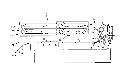
is seen a combined transport/bursting apparatus, generally
designated 10, including a transport and merge section,
generally designated 11, and a bursting section, generally
designate 12. Bursting section 12 includes a pair of lower,
feed rollers 14 and 16 for feeding a web 20 of computer
forms having transverse lines of weakening 22 defining
separate forms. Web 20 initially includes sprocket strips
24 on either side (See Fig. 3) which are engaged by pairs of
adjustable, eight pin needle bearing tractors 26 which feed
web 20 to feed rollers 14 and 16. Situated downstream of
feed rollers 14 and 16 is an adjustable bursting cone 32.
It will be understood that alternate devices such as
bursting balls c:an be used. Downstream of bursting cone 32
is a pair of stepper motor driven bursting rollers 34 and
36. Downstream of bursting rollers 34 and 36 are a pair of
D.C. motor driven, sprocket strip trimmer 28 for removing
sprocket strips 24 from web 20. Upstream of bursting cone
32 are a pair of plates 15 for guiding web 20 to bursting
rollers 34 and 36.
Transport and merge section 11 includes a
conventional belt and pulley assembly comprising a plurality
of upper belts 50 extended over upper, upstream pulleys 52
and downstream pulleys 54, and a plurality of lower belts 60
extended over lower, upstream pulleys 62 and downstream
pulleys 64. The upper reach of lower belts 60 and the lower
reach of upper belts 50 operate to convey sheets fed into
_ CA 02082721 2000-02-10
- 7
transport and merge section 11. There are a pair of stop
rollers 66 and 68 which control the advancement of sheets
being conveyed through transport and merge section 11.
Downstream from the belt and pulley system are upper, feed
rollers 70 and 72 and upper guide plates 74 for conveying
sheets from the belt and pulley system to bursting rollers
34 and 36.
It can be seen that the two paper paths defined by
the two pairs of feed rollers 70 and 72, and 14 and 16
to converge into one paper path at the bursting rollers 34 and
36.
The lower bursting roller 36 is mounted on a shaft 38
on which are mounted a pair of yokes (not shown) which
support the upper, clam-shell housing 42 for the aforesaid
bursting apparatus. As best seen in Fig. 2, the clam-shell
housing 42 supports the upper burst roller 36, the upper
pair of feed rollers 70 and 72, and the belt and pulley
assembly. An open construction of the clam-shell housing 42
provides ready access at all times to sheets in transport
and merge section 11, and by virtue of its ability to pivot
open as seen in Fig. 2, access is provided to the lower web
20. A commercially available gas spring 44 can be
used to maintain clam-shell housing 42 in the open position
so that jams can be cleared, or other problems involvi~tg the
lower web 20 addressed. Downstream of bursting rollers 3~
and 36 is a pair of transport rollers (not shown) for,.
transporting the forms and sheets conveyed through rollers
34 and 36 for further processing.
In bursting section 12, there is a conventional
3o scanning device 80 for scanning control information printed
on control documents in the web. Typically, the control
documents are leading forms for each batch of forms to be
burst. In the preferred embodiment of the present
invention, the control information includes the number of
forms and the number of individual sheets that must be
combined to complete a corresponding batch.
Referring now to Figs 4A-4C, the separate paper paths
are shown merging into one paper path. As seen in Fig. 4B,
web 20 is being burst and an individual sheet 18 has been
CA 02082721 2000-02-10
_ g _
detained at roller pairs 66 and 68. After a predetermined
number of forms have been burst from ~.~eb 20, a predetermined
number of individual sheets 18 are conveyed through burst
rollers 34 and 36, as seen in Fig. 4C. After the
predetermined number of individual sheets 18 are conveyed,
the cycle is repeated with the control document in the web
being scanned to determine the number of forms and
individual sheets that must be accumulated to form a
predetermined batch.
l0 Referring now to Fig. 5, there is shown an inserting
machine configuration including transport and bursting
apparatus 10 of the present invention. Cut sheet feeder 84
feeds individual sheets seriatim into transport and merge
section 11, and web 20 is fed and burst in bursting section
12. According to scanned control information, separated web
forms and individual sheets are merged into one paper path
and accumulated into batches at accumulator module 86. Each
completed batch is conveyed to folder module 88 for folding,
and then to insert module 90 for insertion into an envelope
which is then moistened and sealed at sealer module 92. It
will be understood by those skilled in the art that there
are other applications and configurations of inserting
machines employing the present invention. For example,
individual sheets 18 and separated forms 20 can be
transported directly to folder module 88 for folding,
whereby accumulator module 86 operates as a transport.
The steps required to operate the apparatus include
determining the length of the discrete forms in webs 20 by a
strip length gauge having numerical increments representing
varying form lengths. This number is now used to position
the tractors 26 to a numerically equivalent gauge setting on
the paper path deck to a position such that the first form
will be completely scanned and the lead edge of this form
will advance, when the apparatus is energized to a position
coincident with the center of the burst rollers 34 and 36.
This number is also entered by the operator into a pulse
counting devices) (thumbwheels) for the lower paper path
prior to the operation of the apparatus. The feed rollers
for the lower paper path can be driven intermittently or
20~2~~1
_ g _
continuously, dependent on whether a collated set or one
form/sheet from each paper path is pr~~grammed. Upstream
from the burst cone 30 and 32 but downstream from the feed
rollers 70, 72, 14 and 16 is positioned a sensing device
(not shown) that detects the leading edge of a forna/sheet
from either paper path and sends an appropriate signal to a
pulse generator connected to the burst rollers 34 and 36.
By means of the pulse counting devices) previously set by
the operator and coincident with the leading edge of the
form being sensed, a pulse count is reached that accelerates
the burst rollers 34 and 36 at the appropriate time and
duration to a speed that effectively bursts the form as the
rollers convey the form away from web 20. Prior to
accelerating, the burst rollers 34 and 36, driven by a
separate stepper motor (not shown), are rotating at the same
speed as lower feed rollers 1.4 and 16 and tractor carriage
assembly 26, which are synchronized and driven by stepper
motors. On exiting the burst rollers 34 and 36, the leading
edge of the untrimmed form will enter the trimmers 28 which
were manually positioned to trim off the sprocket strips
that exit in a downward direction while the trimmed and
burst form 20 proceeds to the next downstream device.
The belt and pulley assembly and upper feed roller 70
and 72 of transport and merge section 11 and stop rollers 66
and 68 rotate at the same speed as burst rollers 34 and 36
and are driven ~>y D.C. motors. The belt and pulley assembly
and feed rollersc 70 and 72 rotate continuously. Stop
rollers 66 and E.8 are controlled by a conventional
clutch/brake assembly for detaining individual sheets while
forms are burst in bursting section 12.
This cycle is repeated continuously with no stopping
or delaying of the feed or burst rollers on any one up
(single web) application of collated sets and will stop only
when an end of collation is detected by the scanning device
or when the sense device does not see a gap between forms
which would indicate a stream feed (unburst form) condition.
This transport/bursting machine can also be used in
nonintelligent (no scanning) applications requiring one form
and one individual sheet per cycle.
~0~27~1
It should be understood by those skilled in the art
that various modifications may be made in the present
invention without departing from the spirit and scope
thereof, as described in the specification and defined in
the appended claims.