Note: Descriptions are shown in the official language in which they were submitted.
136'~
TITLE OF THE INVENTION
Method of operating an annular combustion
chamber
BACKGROUND OF THE INVENTION
Field of the Invention
The pre~ent invention concerns a combustion
chamber in accordance with the preamble to claim 1. It
also concerns a method for operating such a combustion
chamber.
Discu~sion of ~ackqround
The transition from conventional tubular
combustion chambers to annular combustion chambers
undoubtedly introduces advantages, at least with
respect to space, because such combustion chamber3
surround the central part of the rotor of the gas
turbine in a regular and annular manner. With respect
to the operating procedure, however, this transition
has not proved optimum to the desired extent, as far a~
~an be seen from the state of the art. It is not
possible to discern an intelligent operating pxocedure
for gaseous fuels who~e flows are available as a
function of the particular operating point,
particularly if it is a sumed that minimized pollutant
emi6sion~ are to be achieved. In other words, the
space advantages which the annular combustion chamber
undoubtedly offers must not be obtained at the expense
of an lncrea~e in the pollutant emission~ from the
combustion.
SUMMARY OF_THE_INVENTION
Aacordingly, one object o the invention is to
provide aid in thi~ re~pect by propo~ing, as specifled
in the claim~, a novel procedure which permits the
pollutant emi~sions to be minimized in a method of the
type ~uoted at the beginning.
The essential advantage of the invention may be
~een in the fact that an optimized operating procedure
can be carried out independent of the size of the
- 2 ~ 362
annular comb~lstion chamber and the number of burners
employed in it.
A further essential advantage of the invention
may be seen in the fact that water or steam i~ often
injected into the flame in order to increase the power
of a gas turbineO In pure premixing burner~, this
often leads to the flame being extinguished or to
vibration problems. In the arrangement selected, an
increasiny proportion of fuel is injected through a
head stage in the burners with increasing water or
steam quantity in such a way aY to prevent the flame
from being extinguished and to prevent vibration prob-
lems occurring.
A further essential advantage of the invention
lies in the favorable overall behavior of the burner~
both during ignition and during operation. The burners
themselves are located at the head of the annular
combu~tion chamber and form, in principle, a double
ring on the front wall. Two burners at a time are
alternatively displaced outwards and inwards in order
to achieve a favorable flow field for combustion. The
burners in each ring have the same direction of
rotation and have the opposite direction of rotation
relative to the burners in the other ring, all this
being done in order to obtain a strong tran~ver~e flow
along the combustion chamber walls and in the center.
As far as the burners themselves are concerned, they
ars divided into piloting and piloted burners, the
latter being present in a smaller number than the
former. The position of the piloted burners is
pre~erably selected in such a way that they are
satisactorily surrounded by the piloting burners; this
leads to good burn-out in the operational range in
which the piloted burners cannot generate their own
flame~ and, in~tead, only inject a very weak mixture
into the hot exhaust gases of the piloting burners.
- 3 ~
Advantageous and useful further developments of
the solution to the object of the invention are speci-
fied in the further dependent claims.
BRIEF DESCRIPTION _OF THE_~WINGS
A more complete appreciation of the invention
and many of the attendant advantage~ thereof will be
readily obtained as the same becomes better understood
by reference to the following detailed description when
considered in connection with the accompanying draw-
ings, wherein:
Figr 1 shows a diagrammatic sector part of the front
wall of an annular combustion chamber,
Fig. 2 shows a front wall of an annular combustion
chamber equipped with burners, the diagram-
matic reproduction of the burners correspond-
ing to the burner~ of the embodiment of Fig.
4-7,
Fig. 3 shows a simulated reproduction of the stream-
lines on the front wall,
Fig. 4 shows a burner in a perspective viewr
Fig. 5-7 show corresponding sections through the
planes V-V (Fig. 5), VI-VI (Fig. 6) and VII-
VII (Fig. 7), the~e sections only reproducing
a diagrammatic, ~implified representation of
the burner of Fig. 4.
DESCRIPTION OF_THE PREFERRED_EMBODIMENTS
Referring now to the drawing~, wherein like
reerence numerals and letters designate identical or
corresponding parts throughout the several views,
wherein all the elements not directly necessary for
under~tanding the invention are omitted and wherein the
flow direction of the media is indicated by arrows,
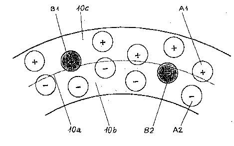
Fig. 1 show~ a sector part of a front wall of an
annular combustion chamber. Reference should be made to
EP-Al 0 401 529 for better understanding of the further
embodiment of the annular combustion chamber. The
annular combustion chamber has a series of burners
whose num~er depends on the size of the machine and the
~C~Z~G2
size of the burners. The main stages, whose
embodiments are preferably confi~ured from the
diagrammatic repre~entation of Fi~. 4, of all the
burners are connected to a fuel supply. The head
stages are collected in two group~ and the burner
proportion per group is matched, fundamentally, to the
particular machine. The two groups differ from one
another in that one group consists of piloting burners
A1, A2 and the other group ~onsists of piloted burners
Bl, B2. Fundamentally, the number of piloting burners
Al, A2 is much greater than the number of piloted
burners Bl, B2. The switching procedure of the annular
combustion chamber considered is based on the ~act that
the compressor of the gas turbine group i5 equipped
with variable inlet guide vane rows so that the air
flow can be reduced by at least 15% xelative to the
full load air flow. When the gas turbine is being
started and run up, the fuel is distributed to the
head stage~, for which reference should be made to Fig.
4-7, of the piloting burners Al, A2. The setting of
the inlet guide vane row i8, in this connection,
immaterial. The inlet guide vane row must be closed,
at the latest, when synchronization with the grid has
taken place. The inlet guide vane row remains closed
up to a load of approximately 65-80%. Beyond this
point, it i~ opened continuously. With increasing
load, the fuel flow to the piloting burners Al, A2 i9
increasingly supplied to the main stage. At some
40-45~ load, the head stages are substantially out of
operation and the piloting burners Al, A2 are operated
in pure premixing mode. Between 40-45% and 65-80%
machine power, the fuel flow to the piloting burners
Al, A2 remains substantially unaltered. The power is
increased by increasing the fuel flow to the main
stages of the piloted burners Bl, B2. As soon as the
fuel flow to all the burners i~ the same, the operating
point is also reached from which the annular combustion
chamber i9 operated with all the burners in purely
zc~
pre-mixed operation. ~eyond thi~ point, the fuel and
air flows are increased substantially in proportion in
order to keep the equivalence ratio at an optimum
value. The burners - both piloting and piloted - form,
in principle, a double ring 10b, 10c on the front wall
10 of the annular combustion chamber, as express~d by
the line of symmetry 10a. However, two burners at a
time are displaced alternately outwards and inwards in
order to obtain a favorable flow field for combustion.
The burners in each ring have the same direction of
rotation, which is opposite to that in the adjacent
ring, as is symbolized by the plu~ and minus signs in
the burners. rrhis configuration causes a strong flow
along the combu~tion chamber walls and in the center.
The position of the piloted burner~ B1, B2 is important
here; they are surrounded a~ well as possible by the
other burner~, i.e. by the piloting burners A1, A2.
rrhis lead~ to good burn-out in the operating range in
which the piloted burners B1, B2 cannot generate their
own flame - as i8 the ca~e in the operating range
between 40-45% and 65 30% - and in which, in~tead, they
only înject a very weak mixture into the hot exhaust
gases of the piloting burners Al, A2.
Fig. 2 shows the complete front wall 10 of the
annular comhu~tion chamber, the piloted burner~ Bl, B2
making up only 1/6 of the total quantity. A proportion
of 5/6 therefore applie~ to the piloting burner~ Al,
A2. This divi~ion represent~ a preferred variant.
Other divisions can certainly be conceived depending on
the type of annular combu~tion chamber.
Fig. 3 ~hows the streamline~ 10d forming on the
front wall 10 during operation, as determined by test.
'rhe configuration of the streamlines 10d has a major
effect on the overall behavior of the combustion
chamber, especially during the ignition procedure. The
closenes~ of the streamline~ 10d indicates a high
velocity and this high veloci~y, which become~
established particularly well - as may be seen - in the
-- 6 ~
region of the line of s~mmetry (see Fig. 1), ensure~
that the ignition can be transmitted from the pilo-ting
burners to the piloted burners.
It is advantageous for better understanding of
the construction of the burner to consider the
individual sections from Fig. 4, which are shown in
Fig. 5-7, at the same time as Fig. 4. Fur~hermore, in
order to make Fig~ 4 as comprehensible a~ possible, the
guide plates 21a~ 21b shown diagrammatically in
Fig. 5-7 are only indicated in Fig. 4. In the
description of Fig. 4 below, reerence is made as
required to Fig. 5-7.
Fig. 4 shows the burner, which has an intrinsi
cally integrated premixing zone, in perspective view.
The burner itself consists of two half hollow partial
conical bodies 1, 2 which are located one upon the
other and whose longitudinal axes of symmetry are radi-
ally offset relative to one another. This offset of
the re3pective longitudinal axes o~ ~ymmetry lb, 2b
(3ee Fig. 5-7) relative to one another frees respective
tangential air inlet slots 19, 20 (see Fig. 5-7) on
both sides of the partial conical bodies 1, 2 so that
the flow is in opposite direction~ and combustion air
15 flow3 through them into the internal space of the
burner, i.e. into the hollow conical space 14 ~ormed by
the two partial conical bodies 1, 2. The conical shape
o~ the partial conical bodie~ 1, 2 ~hown has a certain
~ixed angle in the ~low direction. The partial ~onical
bodies 1, 2 can, of course, ha~e a progressive or
degressive conical inclination in the flow diraction.
The two embodiments last mentioned are not included in
the drawing becau~e they are immediately obvious.
Which ~hape i3 preferred in the end depends essentially
on the particular combustion parameters specified. The
two partial conical bodies 1, 2 each have a cylindrical
initial part la, 2a which forms a continuation of the
partial conical bodie 1, 2 90 that the tangential
inlet slot3 19, 20 are al~o present and extend over the
2CS~J~;2
complete length of the burner. The burner can, of
course, be made purely conical, i.e. without a
cylindrical initial part la, 2a and, in addition, this
initial part does not have to ~e cylindrical. A nozzle
3, the so-called head stage, is accommodated in this
cylindrically configured initial part la, 2a. The fuel
supply to this head stage consists of a central fuel
injection 4 of a liquid fuel 12, preferably oil, and a
substantially coaxial fuel injection of a gaseous fuel
13. The injection of the gaseous fuel 13 takes place
by means of a series of injection openings 13a which
are arranged in the form of a ring around the central
fuel injection 4. In general, the said fuel injections
can involve air-supported injection or pressure
atomization. The fuel injections therefore take place
approximately in the region of the narrowest cross-
section of the conical hollow space 14 formed by the
two partial conical bodies 1, 2. Each of the two
partial conical bodies 1, 2 has a fuel conduit 8, 9 in
the region of the tangential air inlet ~lot 19, 20 and
these 810ts are provided on their longitudinal sides
with a number of openings 17 through whieh a gaseou~
and/or liquid fuel 13 is injected, it being preferable
to use gas. This fuel mixes with the combustion air 15
flowing through the tangential inlet slots 19, 20 into
the hollow conical space 14, as symbolized by the arrow
16. These fuel conduits 8, 9, which form the so-called
main stage of the burner, are preferably placed at the
end of the tangential inlet flow before entry into the
hollow conieal space 1~ in order to aehieve optimum
alr/fuel mixing before the mixture flows into the
hollow eonieal space 14. Mixed operation i8 ~ of
course, possible with both fuel supplies, i.e. one via
the eentral nozzle 3 and one via the ~uel conduits 8,
9. At the combustion space end 22, the outlet opening
of the burner merges into a front wall 10 in which
there are a number of holes 11. These are used for
cooling the burner end surface. Other cooling
- 8 - 2~$~,$~;2
techniques are also conceivable. The liquid fuel 12
flowing through the nozzle 3 is injected with an acute
angle into the hollow conical space 14 in such a way
that a spray pattern which is as homogeneously conical
as possible appears at the burner outlet plane. This
is only possible i the inner walls of the partial
conical bodies 1, 2 are not wetted by the fuel injec-
tion 4. For this purpose, the conical profile 5
consisting of a liquid fuel is surrounded by the
tangentially entering combustion air 15 and, if
necessary, by a further, axially introduced, combustion
air flow which is not visible in the figure. The
concentration of the liquid fuel 12 i~ continuously
reduced in the axial direction by the admixture of the
combustion air flows. If a gaseous fuel 13 is
introduced via the fuel conduits 8, 9, for example,
mixing with the combustion air 15 takes place directly
in the region of the air inlet slots 19, 20. When a
liquid fuel is employed, the injection is correspond-
ingly displaced. Minimized pollutant emission figurescan then be alway~ achieved if complete evaporation
takes place before entry to the combustion zone. The
same also applies to near-~toichiometric operation
where the excess air i5 replaced by recirculated
exhaust gas. In the configuration of the partial coni-
cal bodies 1, 2, tight limit~ have to be applied to the
conical angle and the width of the tangential air inlet
~lots 19, 20 80 as to produce the desired flow field of
the air with the reverse flow zone 6 in the region of
the burner outlet opening. In general, it may be
stated that making the air inlet slots 19, 20 smaller
displaces the rever~e flow zone 6 further upstream,
brinying about earlier ignition of the air fuel
mixture. In this respect, it should be noted that the
position of the reverse flow zone 6, once fixed, is
intrinsically stable because the ~wirl increases in the
direction of flow in the region of the conical ~hape of
the burner. rhe axial velocity of the mixture can also
be influenced by the previously mentioned supply o~ an
axial flow of combustion air. The construction of the
burner is outstandingly suitable for changing the size
of the tangential air inlet slots 19, 20 at a given
overall length of the burner. Thi~ i5 achieved by
displacing the partial conical bodles 1, 2 towards or
away from one another so that the distance between the
two central axes lb, 2b is reduced or increased, the
gap size of the tangential air inlet slot~ 19, 20 also
changing corre~pondingly - as exemplified particularly
well by Fig. 5-7. The partial conical bodies 1, 2 can,
of course, be displaced towards one another in a
different plane and can even be dri~en towards an
overlap. It is, in fact, also possible to push the two
partial conical bodies 1, 2 spirally into one another
by a rotational motion in opposite directions or to
displace them axially relative to one another in the
longitudinal direction. Using simple arrangements, it
i8 therefore possible to vary the shape and size o~ the
tangential air inlet slots 19, 20 arbitrarily ~o that
the burner can be individually matched, within a
certain operational band width, without changing its
overall length.
The geometric configuration of the guide plates
21a, 21b may be seen in Fig. 5-7. They fulfil flow
inlet function~ by extending, in accordance with their
length, the respective end of the partial conical
bodies 1, 2 in the incident flow direction of the com-
bustion air 15. The ducting of the combustion air 15
into the hollow conical space 14 can be optimized by
opening or closing the guide plate~ 21a, 21b about a
center of rotation 23 placed in the region of the inlet
into the hollow conical space 14. Thi~ i9 particularly
necessary when the original gap ~ize of the tangential
air inlet ~lots 19, 20 has to be changed. The burner
can, of course, also be operated without guide plates
or, alternatively, other aids can be provided for this
purpose.
-- 10 --
2~,
Obviously, numerous modifications and
variations of the present invention are possible in
light of the above teachings. I~- is therefors to be
understood that within the scope of the appended
claims, the invention may be practised otherwise than
as specifically described herein.