Note: Descriptions are shown in the official language in which they were submitted.
-` 1 - ;~O$Z~lS
Title: SnMMRR DAMPER FOR FIREPLACE
FIELD OF TÆ INVENTION
This invention relates to fireplaces. In a
preferred embodiment, the invention relates to a balanced
flue, zero clearance fireplace or to a fireplace insert or
to a free-standing fireplace.
R~ C~GRQUND TO THE INVENTION
Various types of fireplaces are known in the
art. One traditional type of fireplace is a masonry
fireplace which is built into a room of a house or other
dwelling unit. Such a fireplace has a masonry firebox and
a masonry chimney exten~ing upwardly to vent above the
roof of a house. While these fireplaces may be decorative,
their heating efficiency is very low. Further, these
fireplaces are necessarily fixed in place and require that
a room be decorated around the location of the fireplace.
One way to solve this problem has been to use a
zero clearance fireplace. Such fireplaces may be
positioned at any desired location in a room. Various
designs for such fireplaces have been developed. Some of
these fireplaces are designed to be energy efficient, i.e.
to transfer some of the heating value of the fuel consumed
in the fireplace to the room in which the fireplace is
situated.
Such fireplaces are also used for their
decorative value. However, due to the heat generated by
their use, high efficiency fireplaces may only be utilized
in the winter when they are used for their supplemental
heating value.
BRIEF DESCRIPTION OF THE INVENTION
It has now been found that this disadvantage may
be overcome by using a fireplace comprising a firebox
having a bottom panel, a top panel, a rear panel and a
flue; an outer casing having a top panel and a rear panel,
the casing being spaced from and surrounding the firebox;
combustion air feed means for supplying combustion air to
~,, ~
- - 2 - 20~91
the firebox; a heat exchanger located downstream from the
flue for selectively receiving combustion gases and for
transmitting the heat from the combustion gases to the air
to be heated; first passage means for conveying the
combustion gases from the flue to a conduit means in
communication with a source external to the room in which
the fireplace is situated for exhausting the combustion
gases from the fireplace; switching means for selectively
coupling the heat exchanger in series with the first
passage means, the switching means being operable between
a first position in which the combustion gases pass
through the heat exchanger before being vented to the
outside and a second position in which the combustion
gases pass through the first passage means, by-passing the
heat exchanger, and are vented to the outside; and second
passage means positioned between the outer casing and the
firebox for circulation of the air to be heated along the
heat exchanger.
The particular design may be used either with a
free-stAn~ing fireplace, a zero clearance fireplace or
with a fireplace insert which is designed to be installed
in a pre-existing solid fuel burning masonry fireplace.
For the purpose of this disclosure, "fireplace" is used to
refer to both a free-stAn~ing fireplace as well as a
fireplace insert. In addition, the fireplace may either
consume a solid organic fuel such as wood, or alternately
a gaseous fuel such as natural gas or propane.
Fireplaces according to the instant design may
be highly decorative and may be used at any time during
the year. When the fireplace has a sealed combustion
chamber, which may occur if the firebox has a door which
is closed, then the amount of heating value from the
combustion gases which is transmitted to the room may be
controlled by limiting, or preventing, the combustion
gases from passing through the heat exchanger.
Accordingly, the fireplace may be used for decorative
value on a summer evening without excessive heat being
~8~15
transmitted to the room in which the fireplace is
situated.
The substance and advantages of the present
invention will be more fully and completely described in
accordance with the following description, and the
accompanying drawings, for a preferred embodiment of the
invention.
BRIEF n~.~rRTPTION OF THE DRAWINGS
Figure 1 is a front perspective view of the
fireplace according to the invention;
Figure 2 is a cross-section along the line 2-2
in Figure 3;
Figure 3 is a cross-section along the line 3-3
in Figure 1 with both the by-pass and the fresh air
dampers closed;
Figure 4 is a cross-section similar to that
shown in Figure 3 but with both the by-pass and the fresh
air dampers open;
Figure 5 is a top view, with the top panel of
the outer casing removed, of a fireplace according to a
second embodiment of the instant invention;
Figure 6 is a cross-section along the line 6-6
in Figure S with both the by-pass and the fresh air
dampers closed;
Figure 7 is a cross-section similar to that of
Figure 6 but with the by-pass and fresh air dampers open;
Figure 8 is a cross-section along the line 3-3
in Figure 1 of a third embodiment of the instant
invention, with the by-pass and the fresh air dampers
closed;
Figure 9 is a cross-section similar to that of
Figure 8 but with the by-pass and fresh air dampers open;
and,
Figure 10 is a partially exploded, top
perspective view of the fireplace.
- 4 - 2 ~ g29
DE~ATT.~n DESCRIPTION OF THE PREFERRED EMBODIM~NT
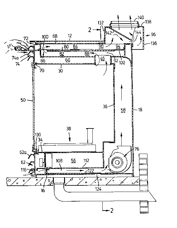
As shown in Figures l, 2 and 3, fireplace lO has
a top casing panel 12, two side casing panels 14, a bottom
casing panel 16, and a rear casing panel 18. Top casing
panel 12, side casing panels 14, bottom casing panel 16
and rear c~sing panel 18 define the top, sides, bottom and
rear respectively of fireplace lO.
Fireplace lO also has right front casing panel
20, left front casing panel 22 and upper front casing
panel 24. These panels are positioned at the side and top
periphery of the front of the fireplace. The inside edge
of right front casing panel 20 is designated by reference
numeral 26 and the inside edge of left front casing panel
22 is designated by reference numeral 28.
Positioned inside the outer casing of the
fireplace is a firebox. The firebox is defined by top
panel 30, right and left side panels 32, bottom panel 34
and rear panel 36. While the firebox is shown as being
rectangular in the attached drawings, the firebox may be
of any desired shape. The outer casing is positioned so as
to be spaced from and so as to surround the firebox.
If the fireplace is designed for burning a solid
organic fuel such as wood, then a grate or other holding
means may be provided on bottom panel 34. Alternately, if
the fireplace is to be used to burn a gaseous fuel, such
as natural gas or propane, then a burner unit may be
provided. As shown in Figure 3, a burner 38 may be
provided in the lower portion of the firebox. As is known
in the art, the gaseous fuel may be supplied to the
firebox through a pipe (not shown) positioned underneath
the firebox. The pipe connects with a regulator (not
shown). The gaseous fuel passes from the regulator to
burner 38 via a pipe (not shown). The burner unit may also
be supplied with an igniter and a flame detector (not
shown).
Flue 46 is provided for exhausting the
combustion gases from the firebox. Accordingly, flue 46 is
- 5 - ~08~5
provided at an upper portion of the firebox. In the
preferred embodiment shown in Figures 3 and 4, the flue is
provided in top panel 30 of the firebox and, in
particular, flue 46 is centrally located in top panel 30
adjacent rear panel 36. Thus, the combustion gases will
rise up through the fireboY~ and enter flue 46. As is shown
in Figure 2, in the preferred embodiment three flues 46
are used to exhaust combustion gases from the firebox.
Alternately, if the fireplace is to be rear vented, flue
46 may be centrally located in rear panel 36 adjacent top
panel 30 (see Figures 6 and 7).
As discussed above, the fireplace may be
equipped to burn either a solid organic fuel, such as
wood, or a gaseous fuel, such as natural gas or propane.
If a gaseous fuel is to be combusted in the fireplace,
then government regulations typically require that the
firebox be sealed. To this end, the firebox may be
provided with door 50 (see Figure 3). Door 50 may be
affixed by any means known in the art to either the
firebox itself or to the outer casing. Further, as shown
in Figure 1, door 50 may also have a transparent panel,
such as a glass window 52 positioned centrally therein.
Optionally, such transparent panels may be provided in
more than one side of the firebox.
By positioning the outer casing so as to be
spaced from and so as to surround the fireplace, a passage
is provided for the circulation of air along the outside
of the panels of the firebox. Generally, any source of air
may be used for circulation through this air passage.
Preferably, the air passage is in communication with the
room in which the fireplace is situated and the room air
is circulated around the fireplace.
As shown in Figures 3 and 4, the air passage may
comprise lower room air plenum 108, rear room air plenum
58 and upper room air plenum 60.
Room air plenum 56 is positioned between bottom
panel 34 of the firebox and bottom casing panel 16. Room
- 6 - ~0~ 5
air plenum 56 may extend substantially the entire width of
the space below the firebox. Room air entry port 62 is
located at the front portion of lower room air plenum 56
and is defined by inside edge 26 of right front casing
panel 20, inside edge 28 of left front casing panel 22,
the front portion of bottom casing panel 16 and the front
portion of bottom panel 34 of the firebox. Grate 62a may
be provided to cover room air entry pcrt 62.
Lower room air plenum 108 is positioned below
room air plenum 56 and is separated therefrom by lower
room air plate 112. Lower room air plenum 108 may extend
substantially the entire width of the space below the
firebox. An entrance, generally designated by reference
numeral 116 is provided at the forward portion of lower
room air plenum 108. Once again, grate 62a may be provided
to cover entrance 116.
Rear room air plenum 58 is located between rear
panel 36 of the firebox and the outer wall defined by rear
casing panel 18. Rear room air plenum 58 may extend across
the entire rear surface of the firebox. If the fireplace
is to be a zero clearance fireplace, and if the
temperature of rear casing panel 18 is greater than
desired, then insulation may be provided along the rear
wall of the fireplace. In such cases, the insulation may
not be required to extend all the way to the bottom
portion of the fireplace but may terminate at a position
in the lower half of the fireplace.
Top room air panel 68 is positioned upwardly
from top panel 30 of the firebox. Upper room air plenum 60
is located between top room air panel 68 and top panel 30
of the firebox. Once again, upper room air plenum 60 may
extend substantially the entire width across the top of
the firebox. As shown in Figure 3, top panel 30 of the
firebox has a front edge 70 and top room air panel 68 has
a front edge 72. Room air exit port 74 is provided at the
front portion of upper room air plenum 60 and is defined
by inside edge 26 of right front casing panel 20, inside
` _ 7 _ 2~8~1S
edge 28 of left front casing 22, front edge 70 of top
panel 30 of the firebox and front edge 72 of top room air
panel 68. Grate 74a may be provided to cover room air
entry port 74.
Accordingly, room air enters lower room air
plenum 108 via room air entry port 62, travels along the
bottom of the firebox and then up the rear of the firebox
through rear room air plenum 58 and then across the top of
the firebox through upper room air plenum 60 to exit the
fireplace via room air exit port 74. As it travels along
this path, the room air is heated by contact with the
walls of the firebox. A blower may be provided to increase
the flow of air through the room air plenums. Blower 76
may be positioned at any desired location in the room air
plenums. As will be appreciated, once fireplace 10 is in
operation, room air would be drawn via natural convection
into room air entry port 62, through the room air plenums
and out room air exit port 74. However, blower 76 could be
oriented to reverse the natural direction of travel of the
room air such that the room air would enter via the top of
the unit, then travel downwardly along rear room air
plenum 58 and out port 62. In the preferred embodiment,
blower 76 is provided towards the rear of lower room air
plenum 108 so as to enh~nce the natural convection of the
room air.
In order to further increase the transfer of
heat from the combustion gases to the room air, side room
air plenums 64, defined by the space between respective
side casing panels and side firebox panels, may be
provided (see Figure 5). With such an arrangement, the
room air which enters via port 62 may travel upwardly
along the rear panel 36 of the firebox and also upwardly
along side panels 32 of the firebox. Upper room air plenum
60 extends across the top of the firebox and is in
communication with rear room air plenum 58 and side room
air plenums 64. Accordingly, the room air, which passes up
rear room air plenum 58 as well as side room air plenums
~ 8 - 20~ 5
64, travels through upper room air plenum 62 and exits the
fireplace via room air exit port 74. It will be
appreciated by those skilled in the art that one or more
of the rear or side room air plenums may be blocked by
placing insulation therein. For example, insulation may be
placed in side room air plenums 64 thus causing all of the
room air to circulate up rear room air plenum 58.
Alternately, insulation may be placed in rear room air
plenum 58 forcing all of the room air to travel up side
room air plenums 64.
As shown in the preferred embodiment of Figures
3 and 4, heat exchanger 80 may be positioned in upper room
air plenum 60. Heat exchanger 80 is positioned in upper
room air plenum 60 between top room air panel 68 and top
panel 30 of the firebox so as to allow the room air to
circulate around heat exchanger 80 as the room air passes
through upper room air plenum 60. In one embodiment, heat
exchanger 80 may comprise a first plenum 82, a second
plenum 84, a generally U-shaped portion 86 connecting the
forward end of first plenum 82 with the forward end of
second plenum 84, an entrance 88 and an exit 90.
A first passage 92 extends from flue 46 to
entrance 88 of heat exchanger 80. A second passage 94
extends from exit 90 of heat exchanger 80 to a dilution
hood generally represented by reference numeral 96. A by-
pass port 98 is positioned adjacent the rear of fireplace
10 and is positioned to provide communication from first
passage 92 to second passage 94.
In order to selectively couple and decouple heat
exchanger 80 in series with first passage 92 and second
passage 94, there is provided a rod 100 having a first
door 102 and a second door 104 attached thereto. First
door 102 is attached to the rear portion of rod 100. First
door 102 is sized and adapted so as to be capable of
sealing by-pass port 98 (see Figure 3). Second door 104 is
attached to a forward portion of rod 100. Second door 104
is sized and adapted to be capable of sealing generally U-
- _ g _ '~ $~
shaped portion 86 of heat exchanger 80 (see Figure 4).
Rod 100 is movable from a first position, as
shown in Figure 3, to a second position, as shown in
Figure 4. Rod 100 may be moved from the first position to
the second position by means of a handle 106. First door
102 and second door 104 are positioned on rod 100 such
that when rod 100 is in the first position, first door 102
seals by-pass port 98 and, when rod 100 is in the second
position, second door 104 seals generally U-shaped portion
86. Accordingly, when rod 100 is in the first position,
combustion gases exit from the firebox into flue 46 and
into first passage 92. The combustion gases then enter
first plenum 82 of heat exchanger 80 through entrance 88,
flow forwardly through first plenum 82, into generally U-
shaped portion 86, then rearwardly through second plenum84, and exit heat exchanger 80 from exit 90 into second
passage 94. The combustion gases then flow from second
passage 94 through dilution hood 96 and then through an
appropriate conduit, such as a chimney, to the outside.
However, when rod 100 is in the second position, heat
exchanger 80 is sealed and the combustion gases pass from
flue 46 through first passage 92, by-pass port 98 and
second passage 94 into dilution hood 96, as is shown in
Figure 4.
By this arrangement, when rod 100 is in the
first position, heat exchanger 80 is connected in series
such that the combustion gases pass through heat exchanger
80. In this mode, the heat transfer from the combustion
gases to the room air circulating through top room air
plenum 60 will be maximized. If the temperature of the
room in which the fireplace is æituated increases too
much, then rod 100 may be moved towards the second
position, as shown in Figure 4, so as to allow part of the
combustion gases to bypass heat exchanger 80 thus
decreasing the amount of heat which will be transferred to
the circulating room air. Alternately, rod 100 may be
moved completely to the second position, as shown in
- lo - ~08Z~15
Figure 4, so as to minimize the amount of heat which is
transferred from the combustion gases to the circulating
room air.
As shown in Figures 3 and 4, the fireplace may
also allow the operator to supplement the room air with
fresh air from an extexnal source. In particular,
fireplace 10 may include fresh air plenum 110 which is
positioned below lower room air plenum 108 and is
separated therefrom by bottom casing panel 16. Second by-
pass port 114 is provided in bottom casing panel 16towards the rear of said panel. Second by-pass port 114
permits communication between fresh air plenum 110 and
lower room air plenum 108. An entrance, generally
designated by reference numeral 118, is provided in the
lower portion of fresh air plenum 110. Entrance 118 is in
communication with a source of fresh air external to the
room in which the fireplace is situated, such as the
outside, via conduit 120.
Air lever 122 is operable between a first
position as shown in Figure 3 and a second position as
shown in Figure 4. Air lever 122 has a rear portion 124
which is sized and adapted to seal second by-pass port
114. Air lever 122 may be moved from the first position to
the second position by means of handle 128 (not shown).
~hen air lever 122 is in the first position, as shown in
Figure 3, second by-pass port 114 is sealed by rear
portion 124. Accordingly, air passes from the room in
which the fireplace is situated through entrance 116,
through lower room air plenum 108 and into rear air plenum
58.
When air lever 122 is moved to the second
position, as shown in Figure 4, then by-pass port 114 is
opened, and the fresh air travels through conduit 120,
through entrance 118, through fresh air plenum 110 and
into lower room air plenum 108.
Room air plenum 56 is in communication with the
interior of the firebox through a plurality of openings
L5
-- 11
130 in lower panel 34 of the firebox. Accordingly, room
air is used for combustion. To ensure proper venting of
the fireplace, fresh air may be admitted to the room by
moving air lever 122 so that second by-pass port 114 is
open. When the second by-pass port 114 is open, fresh air
is entrained with the room air entering lower room air
plenum 108 via entrance 116. This combined air stream
travels through air plenums 58 and 6~ and the resultant
heated air exits to the room. Accordingly, fresh air is
heated prior to being admitted to the room to reduce any
negative pressure which may be created by using room air
as combustion air in the firebox.
As discussed above, the fireplace may also
include dilution hood 96. Dilution hood 96 permits the
combustion gases to combine with room air and for the
mixture thus formed to be exhausted from the fireplace
cavity. As shown in Figures 3 and 10, dilution hood 96
comprises front panel 132, side panels 134, rear panel
136, top panel 138 and exhaust conduit 140. Dilution hood
96 is located on the rear portion of fireplace 10 with a
portion of the dilution hood extending rearwardly and
downwardly therefrom. Dilution hood 96 is positioned above
the exit from second passage 94. Accordingly, as the
combustion gases exit from second passage 94, they enter
dilution hood 96 and pass upwardly through exhaust conduit
140. The rearward portion of dilution hood 96 extends
rearwardly behind the fireplace and allows room air, which
surrounds the fireplace, to enter the dilution hood and
also pass upwardly through exhaust conduit 140. Baffle 142
is provided in dilution hood 96 and extends from a
position on top panel 138 downwardly and rearwardly. The
bottom of baffle 142 defines a passage 144 between the
baffle and the top of the fireplace. Baffle 142 causes the
combustion gases to pass to the rear of the dilution hood,
where they mix with room air, before extending exhaust
conduit 140.
- 12 - 2~ 5
Figures 5, 6 and 7 show an alternative preferred
embodiment of the present invention. In this embodiment,
the heat exchanger 80 is positioned in rear room air
plenum 58 between rear casing panel 18 and rear panel 36
of the firebox. The heat exchanger 80 is positioned in
rear room air plenum 58 so as to allow the room air to
circulate around the heat exchanger 80 as the room air
passes through rear room air plenum 58. As with the
embodiment described above, heat exchanger 80 comprises an
entrance 88, a first plenum 82, a generally U-shaped
portion 86, a æecond plenum 84 and an exit 90. However, in
the embodiment shown in Figures 5, 6 and 7, generally U-
shaped portion 86 connects the lower end of first plenum
82 with the lower end of second plenum 84.
The rear vented embodiment of the present
invention shown in Figures 5, 6 and 7 also includes a rod
100 and a door 93 affixed to the rear portion of rod 100.
Preferably, rod 100 is located in upper room air plenum
60. Door 93 is sized and adapted so as to be capable of
sealing alternately by-pass port 98 and exit 90.
Rod 100 is movable from a first position, as
shown in Figure 6, to a second position as shown in Figure
7. When in said first position, door 93 seals by-pass port
98. Accordingly, the combustion gases exit from the
firebox into flue 46 and into first passage 92. The
combustion gases then enter first plenum 82 of heat
exchanger 80 through entrance 88, flow downwardly through
first plenum 82 into generally U-shaped portion 86, then
upwardly through second plenum 84, and exit heat exchanger
80 from exit 90. The combustion gases then flow through
dilution hood 96 and then through a conduit, such as a
chimney, to the oùtside. When rod 100 is in the second
position, as shown in Figure 7, door 93 seals exit 90.
Accordingly, when rod 100 is in the second position, the
combustion gases exit from the firebox into flue 46, into
by-pass port 98 and then into dilution hood 96.
~- - 13 - 2~2~5
Rod 100 may be moved from the first position to
the second position by means of a handle 106. When rod 100
is in the first position, heat exchanger 80 is connected
in series such that combustion gases pass through heat
exchanger 80. When rod 100 is in the second position, heat
exchanger 80 is decoupled and the combustion gases do not
flow therethrough.
A further embodiment of the present invention is
illustrated in Figures 8 and 9. In this embodiment, the
heat exchanger 80 is a single pass heat exchanger. As in
the first preferred embodiment described above, heat
exchanger 80 is positioned in upper room air plenum 60. A
first flue passage 150 is provided proximate the rear
panel 36 of the firebox and a second flue passage 152 is
provided proximate the front of the firebox.
In order to selectively couple heat exchanger 80
with first passage 92, rod 154, first door 156 and second
door 158 are provided. Rod 154 is positioned in heat
exchanger 80. First door 156 is attached to the rear
portion of rod 154 and second door 158 is attached to the
forward portion of rod 154. First door 156 is sized and
adapted so as to be capable of sealing first flue passage
150. Second door 158 is sized and adapted so as to be
capable of sealing second flue passage 152.
Rod 154 is movable from a first position, as
shown in Figure 8, to a second position, as shown in
Figure 9. First door 156 and second door 158 are
positioned on rod 154 such that when rod 154 is in the
first position, first door 156 seals first flue passage
150 and second flue passage 152 is open and, when rod 154
is in the second position, second door 154 seals second
flue passage 152 and first flue passage 150 is open.
Accordingly, when rod 154 is in the first
position, the combustion gases exit the firebox through
second flue passage 152, pass through heat exchanger 80
into first passage 92 and exit into dilution hood 96.
However, when rod 154 is in the second position,
~ - 14 - ~ ~ ~29~5
combustion gases exit the firebox through first flue
passage 150 and pass into dilution hood 96, by-passing
heat exchanger 80. Rod 154 is movable between the first
position and the second position by means of a handle 160,
which is releasably attachable to rod 154.