Note: Descriptions are shown in the official language in which they were submitted.
~830 07
BACKGROUND OF THE INVENTION
This inventlon relates to an lmaglng lamlnate having
between a palr of sheets a layer of franglble image-forming
substance separable to the respective sheets thereof. More
partlcularly, lt relates to a laminar structure particularly
adapted to separation of the sheets thereof by mechanlcal
apparatus.
Lamlnar lmaging materlals comprlslng a palr of
sheets and a layer of lmage-forming substance therebetween
have been known. For example, laminar thermal lmaglng
materlals for the productlon of lmages by exposure to heat and
separatlon of the sheets thereof have been descrlbed ln Unlted
States Patent 3,924,041 (lssued December 2, 1975 to M.
Mlyayama, et al.); ln Unlted States Patent 4,157,412 (lssued
June 5, 1979 to K.S. Deneau); and ln Internatlonal Patent
Application No. PCT/US87/03249 of M.R. Etzel (published June
16, 1988 as International Publicatlon No. WO 88/04237~. It
wlll be appreclated that an lmage-formlng substance conflned
between a palr of sheets wlll be protected agalnst abrasion
and rub-off. In addition, a laminar medlum can be handled as
a unltary structure, thus, obvlatlng the requlrement of
brlnglng the respective sheets of a two-sheet imaglng medlum
into proper position in a printer or other apparatus used for
imaging of the medium material.
In the aforementioned Internatlonal Patent
Publlcatlon No. WO 88/04237, there are described certain
preferred embodiments of a high resolution thermal imaglng
medlum, which embodiments include a porous or partlculate
-- 1 --
63356-1854
~,
an s 3 0 0 7
image-formlng substance ln a lamlnate structure between a palr
of sheets. Upon separatlon of the respectlve sheets after
laser exposure of portions or reglons of the medium, a pair of
complementary lmages ls obtained.
In published European Patent Application 91116452.3,
Publication No. 0 481 265 A2, publlshed Aprll 22, 1992, there
are dlsclosed certaln preferred laminar thermal imaging
materlals, ln the form of lndlvldually slzed (formatted)
thermal imaglng lamlnates. These laminates lnclude a marginal
(tab) portlon to facllltate separatlon of the respectlve
sheets of the lamlnate after a suitable laser scanning
exposure. Accordlng to a preferred embodlment dlsclosed
therein, the marginal (tab) portion is provided by a score
line which severs a marginal portion of one of the sheets and
the frangible layer from the remainder of such sheet and
layer. Individual (formatted) thermal imaglng laminates of
the type shown in European Publication No. 0 481 265 A2 can be
stacked in a cassette for supply to a drum or other zone of a
prlntlng apparatus and, after thermal exposure, can be
separated by an automated delamination device. A suitable
such device is described therein.
As ls dlsclosed ln European Publlcatlon No. 0 481
265 A2, and in the aforementioned International Publication
No. WO 88/04237, the lmage-formlng substance of the thermal
imaging media thereof ls designed to fracture vertically,
l.e., ln a dlrection normal to the surface of the layer of
image-forming substance. Vertical frangibility of the image-
formlng layer permits the productlon of images of deslrably
63356-1854
~30 07
high resolution and optlcal density. The apparatus described
in the aforementioned European Publication No. 0 481 265 A2,
in an automated fashion, initiates separation of the sheets of
an exposed film unit at the leading (tab) edge thereof and
completes the delamination process, for vertical fracture and
separation of abutting regions of image-forming substance.
Other apparatus for and methods of delaminatlng
formatted thermal imaging lamlnates of the type descrlbed ln
European Publication No. 0 481 265 A2 are described in Unlted
States Patent No. 5,141,584, lssued August 25, 1992, for
APPARATUS AND METHOD FOR CONTROLLING THE DELAMINATION OF A
LAMINATE.
While various embodiments of mechanical apparatus
can be employed to initlate and complete the separatlon of the
sheets of a composite structure having a marginal portion as
aforesaid, it has been found that undeslred delamination of
the composite tab or marginal portion can occur as the result
of physical stresses applied by mechanical delamination
apparatus to the tab end of the laminate during operation of
the delamination process. It will be appreciated that a
complete or partial delamination of the composite tab portion,
and entanglement of a detached tab portion ln the
63356-1854
~i
20~3Q~ ~
delamination apparatus or larger apparatus of which the
delamination apparatus is a part, will be particularly
disadvantageous and will hamper the efficient operation
of any such apparatus. Accordingly, there will be
interest in a laminar composite structure of the
aforedescribed type having a tab portion which exhibits
a substantial resistance to detachment from the
remainder of the structure.
SUMMARY OF THE INVENTION
It has been found that a composite laminate
having a marginal or tab portion for facilitation of the
desired separation of respective sheets thereof can be
substantially improved in its suitability for
delamination by mechanical apparatus by providing an
improved composite marginal or tab structure, the layers
of which are bonded to one another substantially more
strongly than the corresponding layers of the major and
remaining portion of the composite laminate.
In an article aspect, the present invention
provides a composite laminar structure, comprising;
a frangible layer of an image-forming
substance, said layer having first and second opposite
surfaces;
a first sheet adhered to said first surface at
a first strength, abutting areas of said frangible layer
being, upon exposure of said laminar structure to
intense radiation, adherable to said first surface at a
second strength greater than said first strength;
a second sheet congruent with said first sheet
and adhered to said second surface at a predetermined
substantially uniform strength, said predetermined
208~007
substantially uniform strength being greater than said
first strength and less than said second strength; and
a marginal portion for facilitating separation
of said sheets after said exposure, said marginal
portion being defined by a cut line severing a marginal
portion of one of said sheets and said frangible layer
from the remainder of said one sheet and layer;
the marginal portion of said one sheet being
adhered through said frangible layer to the other of
said sheets substantially more strongly than is the
remainder of said one sheet to said other of said
sheets.
According to a method aspect of the present
invention, there is provided a method of preparing a
laminar composite structure which comprises the steps
of:
providing a composite laminar structure, said
composite laminar structure comprising a pair of sheets
having therebetween at least a layer of vertically
frangible image-forming substance preferentially adhered
to one sheet of said pair of sheets, the preferential
adhesion of abutting portions of such layer of image-
forming substance for said one sheet being reversible in
areas of predetermined imaging exposure of said
composite laminar structure and being attachable to the
other of said pair of sheets as a result of said
exposure, for provision of a pair of complementary
images upon separation of the sheets after said
exposure;
cutting said composite laminar structure into
individual laminar units of predetermined size;
- 2083Q07
defining a marginal portion of said laminar
units by cutting a marginal portion of one of said
sheets and said frangible layer from the remainder of
said one sheet and layer; and
securing said defined marginal portion of said
one sheet substantially more strongly to the other of
said pair of sheets than said remainder of said one
sheet to said other of said sheets.
BRIEF DESCRIPTION OF THE DRAWINGS
Reference is made to the accompanying drawings
in which there are shown illustrative embodiments of the
invention, from which its novel features and advantages
will be apparent, wherein:
FIG. 1 is a perspective view of a preferred
embodiment of a composite laminar structure of the
invention.
FIG. 2 is a view in longitudinal section of
the composite laminar structure of FIG. 1, shown in a
state of partial separation and depicting certain
aspects of its separation into complementary images,
with thicknesses of its layers being exaggerated for
clarity;
FIG. 3 is a diagrammatic cross-sectional view
of another and preferred embodiment of a composite
laminar structure of the invention, with thicknesses of
its layers being exaggerated for clarity; and
FIG. 4 is a diagrammatic cross-sectional view
of the composite laminar structure of FIG. 3, shown in a
state of partial separation and depicting certain
aspects of its separation into complementary images.
- ~8~0 ~7
DETAILED DES~ LlON OF THE INVENTION
Referring now to the drawings, and particularly to
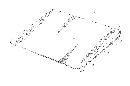
Figures 1 and 2, a laminar composite structure 10 is shown in
a preferred embodiment as a thermal lmaging film unit of the
general kind disclosed by the aforementioned International
Publication No. WO 88/04237 and the aforementioned European
Publicatlon No. 0 481 265 A2. The film unit comprises support
sheets 12 and 14, each adheslvely connected to opposite sur-
faces of a franglble layer 16 of lmage-forming substance 16.
For purposes of the present invention, it is sufficient to
note that layer 16 is such that it may be ruptured or frac-
tured in a direction normal to its two surfaces, i.e., along
lines defined by exposure, as is described in the Interna-
tional Publication No. WO 88/04237, supra. Portions of layer
16 subjected to exposure can then be separated from portions
not affected by exposure to provide complementary images on
the respective sheets of the composite sheet structure.
As used herein, reference to vertical frangibility
of layer 16 is intended to refer to the capacity of abutting
portions of the layer 16 of image-forming substance to be
separated, as a function of a predetermined lmaglng exposure
of the composite laminar structure, along a directlon normal
to the surfaces of the layer. Thus, on separatlon of the
respectlve sheets of the composite laminar structure, a pair
of complementary images of desired hlgh resolutlon and optlcal
density is obtained. It will be understood that the separa-
tion of abutting regions or areas of franglble layer 16 for
production of complementary images in
63356-1854
20~3û~3~
image-forming substance will require that the layer have
sufficient cohesivity as to preclude the partitioning of
regions of layer 16 by fracture between its surfaces,
i.e., along horizontal lines. Since layer 16, as
described in greater detail hereinafter, can be
associated with additional layers for proper imaging of
the composite structure, cohesive failure along
horizontal lines is permissible and desirable in
particular instances, provided that such failure does
not occur with a layer, such as a pigment layer, which
provides desired optical density.
As used herein, and except where otherwise
specified, "adhesion" of a layer or "connection" of a
layer to a sheet or other layer or surface refers to
adhesion or connection either directly or indirectly.
Thus, the layer can be adhered or connected to a sheet
or other layer or surface by being contiguous therewith
or by adhesion or connection through one or more other
layers.
According to a preferred embodiment of the
composite laminar structure 10 of FIG. 1, layer 16 will
comprise a frangible layer of image-forming substance
such as a layer of colorant (e.g., carbon black) in a
suitable binder. Such a layer can be deposited onto
sheet 12 using known coating methods, for provision of a
thin layer having desired and predetermined optical
density. Sheet 12 can comprise polyester or other
material having, for example a subcoat of heat-
activatable polymeric material (not shown) for more firm
attachment of exposed regions of layer 16 to sheet 12 as
a function of a laser exposure. In general, layer 16
will comprise a frangible layer which is adhered to
2083Q~ ~
sheet 12 at a first strength sufficient to prevent
accidental dislocation, but which as a function of
exposure can be more firmly secured to sheet 12 at a
second and greater strength. Shown in the embodiment of
FIG. 1 is a sheet 14 which is adhered to layer 16,
typically through adhesive and release layers (not
shown). Sheet 14 is adhered to layer 16 at a strength
which is greater than the aforesaid first strength, such
that, layer 16 is preferentially adhesive to sheet 14
prior to exposure. Upon exposure and heat activation of
the surface between sheet 12 and layer 16, the
preferential adhesion of layer 16 for sheet 14 is
reversed, i.e., exposed regions of layer 16 are now
connected or attached more firmly to sheet 12, at a
strength greater than the aforesaid first strength and
greater than the bond strength between sheet 14 and
layer 16. Since the adhesion of sheet 14 to layer 16 is
greater in non-exposed regions than the initial strength
between coated layer 14 and sheet 12, separation of
sheets 12 and 14 after image exposure results in non-
exposed regions of layer 16 being separated from the
layer to sheet 14.
As is shown in FIG. 2, and as a result of
laser exposure of the depicted and preferred embodiment,
portions 16a of layer 16 become more firmly bonded to
sheet 12. Portions 16a of layer 16, and abutting
portions 16b which have not been affected by heat, may
then be separated from each other when the sheets 12 and
14 are delaminated.
The sheets 12 and 14 may be made of the same
or of different material, polyethylene terephthalate,
polystyrene, polyethylene, polypropylene, copolymers of
~830 07
styrene and acrylonitrile, polyvinyl chloride, polycarbonate
and vinylidene chloride belng some but not all of the materlal
sulted as support sheets. They may themselves be laminar
structures provided wlth a backlng of paper ~not shown) or any
other material suited for any speclfic purpose. It will be
understood that the backing material should be transmissive of
exposing radiation or be either removable to permit exposure,
or posltloned on a sheet opposed from that through whlch
exposure is accomplished. While it is not a requirement, it
has been found to be advantageous to have one of the sheets
stiffer, i.e., less flexible than the other. The difference
ln stlffness may be provlded by a dlfference ln the materlals
of whlch the sheets 12 and 14 are made. Preferably, however,
and as shown, the dlfferent stlffnesses are attalned by one of
the sheets 12 belng thlnner than the other sheet 14.
For purposes mentloned prevlously, sheet 12 ls
provlded wlth a marglnal portlon 18 whlch extends beyond an
ad~acent margln 20 of sheet 14. As a matter of efflclent
manufacture, and as shown, the marglnal portlon (or tab) 18 ls
provlded by portlon 22 of sheet 14 whlch ls cut or severed
from sheet 14 by a score or cut llne 24 along margin 20 of
sheet 14.
As can be appreclated from Flgure 2, tab portlon 18
facllltates the separatlon of sheets 12 and 14 after exposure.
Separatlon or delamlnation of sheets 12 and 14 is accomplished
using delamination apparatus, such as the apparatus described
in the aforementioned European Publication No. 0 481 265 A2
and in the aforementioned United States Patent No. 5,141,584.
-- 10 --
~ 63356-1854
Separation of sheets 12 and 14 using such apparatus involves
the appllcatlon of physlcal stresses to the common free edge
26 of marginal portions 18 and 22 and intermedlate layer 16.
Such stresses can result in delamination of portion 22 of tab
18 from sheet 12.
As has been mentioned previously, layer 16 is
lnltlally bonded to layer 12 sufficiently to prevent
accidental dlslocation. Such lnitial bonding strength
facilltates removal of non-exposed regions of layer 16 to
sheet 14, ln the ma~or area 14 (Figure 1) of composite laminar
structure 10. The relatively weak adhesion between layer 16
and sheet 12 makes possible, however, the accidental delamina-
tion or detachment of marginal sheet portion 22 from the
composite tab structure 18, in the form of a narrow strip that
can be entangled ln the delaminatlon apparatus. Since the tab
portion comprises a narrow strip 22 of sheet 14 laminated to
sheet 12 through a correspondlngly narrow strip or layer of
lmage-forming substance, an initiated delamination of strip 22
can be propagated readily by application of further stress to
the composite tab structure, resulting in a complete detach-
ment of marginal portlon or strlp 22.
-- 11 --
63356-1854
A
2083007
According to the present invention, marginal
portion 22 is caused to be adhered to sheet 12
substantially more strongly than the remainder of sheet
14. A secure bonding of portion 22 to sheet 12 can be
accomplished in a number of ways and, for example, can
be effected by resort to mechanical or chemical methods,
or by using a combination of mechanical and chemical ~-
treatments. Preferably, the securing of marginal
portion 22 to sheet 12 will be the result of a
convenient operation conducted during the manufacture of
the formatted composite laminar structure 10 of FIG. 1.
A convenient method of manufacturing laminates
of the type shown in FIG. 1 involves the production of
an endless web of laminar material comprising sheets 12
and 14 and layer 16 therebetween, and the cutting
therefrom of individually sized (formatted) film units
of a predetermined size. Such units can be cut from a
web of material using known slitting and cutting
apparatus.
From FIG. 1, it can be seen that preferred
composite laminate 10 comprises congruent sheets 12 and
14. The periphery of composite laminar structure 10 can
be defined by a cutting and stamping operation. The
cutting of sheet 14 along cut or score line 24 can be
accomplished using any of a variety of cutting means,
such as a stamping die a straight-edge cutting knife
moved translationally along line 24, a laser cutter, or
a rolling knife or rotary or swing die traversed along
line 24. Line 24 can be cut any convenient time in the
manufacturing process, i.e., before, after or
simultaneously with the cutting of the periphery of
composite laminar structure 10 from the web material
20~007
-13-
from which it is made, or before or after such cutting.
It will be seen from FIG. 2, that sheet 14 is
cut along line 24 only through frangible layer 16 to
provide a composite tab structure which defines also the
major portion of sheet 14. The length of the composite
laminar structure 10 measured between the score line 24
and a rear edge may typically be about 25.5 cm (10 in.),
its width may be about 20 cm (8 in.), and the dimension
of the marginal portion 18 between its forward edge 26
and the score line 24 may be about 6.5 mm (.25 in.).
The thicknesses of the sheets 12 and 14 measure,
respectively, about 0.013 to 0.178 mm (0.5 to 7 mil) and
0.038 to 0.0254 mm (1.5 to 10 mil), good results having
been obtained with sheets of thicknesses of 0.044 and
0.178 mm (1.75 and 7 mil), respectively. Other
dimensions may, of course, be substituted. Preferably,
the corners of the sheets 12 and 14 are rounded.
In a common free edge 26 of the marginal
portions 18 and 22 and the intermediate layer 16 there
is provided a notch 28 which may conveniently serve as
an alignment means for correctly placing the laminar
film unit 10, or a plurality thereof, in a cassette (not
shown) provided with a complementary protrusion in an
orientation to ensure that the sheet 12 is facing
upwardly from proper placement within the apparatus of
this invention.
Marginal portion 22 of sheet 14 can be
securely affixed to sheet 12 by the application of heat
and pressure to composite tab structure 18. A pair of
opposed dies for application of heat and pressure to the
outer surfaces of sheets 12 and 14 of tab 18 can be used
to increase adhesion by softening, fusion or
- 20~3~07
interpenetration of layers therebetween. Either or both
of the dies can have smooth or textured surfaces.
Conditions of heat and pressure will vary with the
particular nature of the laminar composite structure.
Typically, good results can be obtained by using
pressures in the range of about 20 to about 80 lbs/in2
(138 to 552 Kilopascals) at temperatures of from about
38C. to about 71C (100F to 160F).
In general, heat and pressure will be applied
to the opposed surfaces of composite tab structure 18
for a dwell time than will vary with the nature of the
layers of the composite structure. In general, the tab
portion will be strengthened within a short dwell time
which typically will range from less than one second to
normally not more than about ten seconds, e.g., in a
range of from two to three seconds.
If desired, the securement of marginal portion
22 to sheet 12 can be effected using a plurality of
spaced pins for piercing through the composite at
predetermined locations within marginal portion 22.
Preferably, from the standpoint of maintaining relative
flatness and smoothness of tab 18 and avoiding punctured
surface irregularities, a pair of die surfaces having
relatively smooth surfaces will be desired. Die
surfaces having surface structure sufficient to provide
minor deformations or embossments and substantial
strengthening of tab 18 can also be used. For example,
dies which provide a pattern or engravement in the
nature of stippling provide a strongly bonded tab
portion and will be preferred.
If desired, chemical adhesion and treatments
can be used to promote a strengthened bond between
~3Q ~7
-
marginal portlon 22 and sheet 12. In International Publica-
tion No. WO 92/09441, published June 11, 1992 there are
described certain hardenable (curable) adheslve compositions
for the production of thermal imaging lamlnates. Such
adhesive compositlons lnclude those whlch contain a polymeric
blnder and a polymerizable monomer and which after laminatlon
can be cured by exposure to ultravlolet (UV) lrradiatlon.
In the productlon of composlte lamlnar structures of
the type shown in Figures 1 and 2, a curable adheslve of the
aforedescrlbed type can be used for laminatlon of sheet 14 to
a sheet carrylng a coated layer 16 of lmage-forming substance.
After the cuttlng of formatted unlts, the lndlvldual unlts can
be subiected to a source of ultravlolet for the curlng of the
adheslve of only the ma~or portlon of the composlte structure.
A mask can be used to prevent the blanket UV exposure from
curlng the adheslve layer ln tab 18. Polymerlzable monomer
from the uncured adheslve layer permeates the composlte tab
structure and generates a degree of tacklness whlch promotes a
strong bondlng of marglnal portlon 22 of sheet 14 to sheet 12.
The strength of thls bond ls markedly greater than the
predetermlned bond strength existing between the major portion
of sheet 14 and sheet 12.
An effective bondlng of marglnal portlon 22 to sheet
12 can be effected by a combination of adheslvlty promoted by
the use of a tacky and uncured adhesive
63356-1854
A
. ~08300 7
-16-
layer and by application of heat and pressure.
Reference is made to the adhesion of marginal
portion 22 of sheet 14 to sheet 12 substantially more
strongly than the remainder of sheet 14 is adhered to
sheet 12. In general, tab portion 18 need be
strengthened by mechanical and/or chemical means
sufficiently to prevent partial or complete delamination
of sheet portion 22 upon application of stresses thereto
by an automated delamination device. Good results can
be obtained, for example, by strengthening the composite
tab structure so that the peel strength required for
separating the marginal portion is twice or more than
that needed to separate the major portion of sheet 14
from sheet 12. The amount of required strengthening
will vary, however, with the particular laminar
composite structure. In a structure such as that
described in FIGS. 3 and 4, a peel strength in the major
area will typically be in the range of about 0.8
grams/cm of width to about 8 g/cm of width. In such a
case, tab strength can be increased to a peel strength
in the range of from 1.6 to 16 g/cm of width or higher.
In a preferred structure, such as is shown in FIG. 3,
good results are provided where the peel strength in the
major area is in the range of from 1.1 to 2.8 g/cm and
the peel strength in the tab area is from 2.2 to 5.6
g/cm, or more.
While a principal advantage of the
strengthened tab structure of the composite laminar
structures of the invention will be to permit separation
of the sheets thereof by automated delamination
apparatus without tab delamination, the improved
strength of the tab structure will confer benefits where
2083QOi7
other forms of physical stress are applied to the
structure. Thus, the formatted film units will be
protected against tab delamination that may otherwise
occur as the result of the physical stresses associated
with the manufacture, stacking, packaging or other
handling of the film units or which occur during
processing of the film units in a printer or other
apparatus.
Turning now to FIG. 3, there is shown a
particularly preferred embodiment of a composite laminar
structure of the invention, in the form of a thermal
imaging laminar medium for the production of a pair of
high resolution images by laser exposure. The laminar
medium of FIG. 3 is shown in FIG. 4 in a state of
partial separation.
Thermal imaging medium 30 includes a first
sheet material 32 ~comprising sheet material 32a and
heat-activatable zone or layer 32b) having superposed
thereon, and in order, porous or particulate image-
forming layer 34, release layer 36, polymeric "bridge"adhesive/barrier layer 38, polymeric adhesive layer 40
and second sheet 40. In Fig. 3 is shown a cut line 44
for defining a tab or marginal portion 48 (FIG. 4) which
facilitates the separation or delamination of medium 30
into a pair of complementary images. The various layers
of medium material 30 are described in detail
hereinafter.
Sheet 32 comprises a transparent material so
that image-forming radiation can be transmitted
therethrough for the imaging of medium 30. Among
suitable materials are those mentioned previously in
connection with sheets 12 and 14. An especially
20~3Q~ ~
-18-
preferred sheet material from the standpoints of
durability, dimensional stability and handling
characteristics is polyethylene terephthalate.
Heat-activatable zone or layer 32b provides an
essential function in the imaging of medium material 30
and comprises a polymeric material which is heat
activatable upon subjection of the medium to brief and
intense radiation, so that, upon rapid cooling, exposed
portions of the surface zone or layer are firmly
attached to porous or particulate image-forming layer
34. If desired, surface zone 32b can be a surface
portion or region of sheet 32, in which case, layers 32a
and 32b will be of the same or similar chemical
composition. In general, it will be preferred that
layer 32b comprise a discrete polymeric surface layer on
sheet material 32a. Layer 32b will desirably comprise a
polymeric material having a softening temperature lower
than that of sheet material 32a, so that exposed
portions of image-forming layer 34 can be firmly
attached to sheet 12(12a). A variety of polymeric
materials can be used for this purpose, including
polystyrene, poly(styrene-co-acrylonitrile), poly(vinyl
butyrate), poly(methylmethacrylate), polyethylene and
poly(vinyl chloride).
The employment of a thin heat-activatable
layer 32b on a substantially thicker and durable sheet
material 32a permits desired handling of sheet 12 and
desired imaging efficiency. The use of a thin heat-
activatable layer 32b facilitates the concentration of
heat energy at or near the interface between layers 32b
and- image-forming layer 34 and permits optimal imaging
effects and reduced energy requirements. It will be
2083007
--19--
appreciated that the sensitivity of layer 32b to heat
activation (or softening) and attachment or adhesion to
layer 34 will depend upon the nature and thermal
characteristics of layer 32b and upon the thickness
thereof.
Typically, sheet material 32 will vary in
thickness from about 0.5 mil to seven mils (0.013 mm to
0.178 mm). Good results are obtained using, for
example, a web material 32a having a thickness of about
1.5 to 1.75 mils (0.038 mm to 0.044 mm) carrying a layer
32b of poly(styrene-co-acrylonitrile) having a thickness
of about 0.1 micron to five microns.
Image-forming layer 34 comprises an image-
forming substance deposited onto heat-activatable zone
or layer 32b as a porous or particulate layer or
coating. Layer 34, also referred to as a
colorant/binder layer, can be formed from a colorant
material dispersed in a suitable binder, the colorant
being a pigment or dye of any desired color, and
preferably, being substantially inert to the elevated
temperatures required for thermal imaging of medium 30.
Carbon black is a particularly advantageous and
preferred pigment material. Preferably, the carbon
black material will comprise particles having an average
diameter of about 0.1 to 10 micrometers (microns).
Although the description hereof will refer principally
to carbon black, other optically dense substances, such
as graphite, phthalocyanine pigments and other colored
pigments can be used.
The binder for the image-forming substance or
layer 34 provides a matrix to form the porous or
particulate substance thereof into a cohesive layer and
208300~
-20-
serves to adhere layer 34 to heat-activatable zone or
layer 32b. Layer 34 can range in thickness and
typically will have a thickness of about 0.1 micron to
about 10 microns. In general, it will be preferred form
the standpoint of image resolution, that a thin layer be
employed. Layer 34 should, however, be of sufficient
thickness to provide desired and predetermined optical
density in the images prepared from imaging medium 30.
Suitable binder materials for image-forming
layer 34 include gelatin, polyvinylalcohol, hydroxyethyl
cellulose, gum arabic, methyl cellulose,
polyvinylpyrrolidone, polyethyloxazoline, polystyrene
latex and poly(styrene-co-maleic anhydride). The ratio
of pigment (e.g., carbon black) to binder can be in the
range of from 40:1 to about 1:2 on a weight basis.
Preferably, the ratio of pigment to binder will be in
the range of from about 4:1 to about 10:1. A preferred
binder material for a carbon black pigment material is
polyvinylalcohol.
For the production of images of high
resolution, it will be essential that image-forming
layer 34 comprise materials that permit fracture
substantially along the direction of arrows 50, 50',52
and 52', shown in FIG. 4, and that have a degree of
cohesivity in excess of its adhesivity for heat-
activatable zone or layer 32b. Thus, on separation of
sheets 32 and 42 after imaging, layer 34 will separate
in non-exposed areas from heat-activatable layer 32b and
remain in exposed areas as porous or particulate
portions 34a on sheet 32. Layer 34 is an imagewise
disruptible layer owing to the porous or particulate
nature thereof and the capacity for the layer to
20~ 3Q07
-21-
fracture or break sharply at particle interfaces.
Shown in FIG. 3, is release layer 36 which is
included in thermal imaging medium 30 to facilitate the
separation of images according to the mode shown in FIG.
4. Release layer 36 is designed such that its
cohesivity or its adhesion to either adhesive/barrier
layer 38 or porous or particulate layer 36 is less, in
exposed regions, than the adhesion of layer 34 to heat-
activated zone or layer 32b. The result of these
relationships is that release layer 36 undergoes an
adhesive failure in exposed areas at the interface
between layers 36 and 37, or at the interface between
layers 34 and 36; or, as shown in FIG. 4, a cohesive
failure of layer 36 occurs within the layer, such that
portions (36b) are present in image 30b and portions
(36a) are adhered in exposed regions to porous or
particulate portions 34a. Portions 36a of release layer
36 serve to provide surface protection for the image
areas of image 3Oa, against abrasion and wear.
Release layer 36 can comprise a wax, wax-like
or resinous material. Microcrystalline waxes, for
example, high density polyethylene waxes available as
aqueous dispersions, can be used for this purpose.
Polymeric or resinous materials such as
poly(methylmethacrylate) and copolymers of methyl
methacrylate and monomers copolymerizable therewith can
be employed. If desired, hydrophilic colloid materials,
such as polyvinylalcohol, gelatin or hydroxyethyl
cellulose can be included as polymer binding agents.
Resinous materials, typically coated as
latexes, can be used and latices of poly(methyl
methacrylate) are especially useful. Cohesivity of
2083~7
-22-
layer 36 can be controlled so as to provide the desired
and predetermined fractioning. Waxy or resinous layers
which are disruptible and which can be fractured sharply
at the interfaces of particles thereof can be added to
the layer to reduce cohesivity. Examples of such
particulate materials include, silica, clay particles
and particles of poly(tetra-fluoroethylene).
Shown in FIGS. 3 and 4, over release layer 36,
is polymeric "bridge" adhesive/barrier layer 38. One
function of layer 38 is that of an adhesive to assist in
the lamination of a sheet 32 carrying layers 34, 36 and
38 to sheet 42 carrying adhesive layer 40. In the
production of medium 30, a preferred practice is to
provide first and second elements, the first element
comprising sheet 32 (carrying layers 34, 36 and 37) and
the second element comprising sheet 42 carrying adhesive
layer 18; and to, then, laminate the elements with their
respective sheets outermost int a unitary laminate.
This procedure provides an adhesive-to-adhesive contact
between layers 38 and 40 and a substantially uniform
bonding of the elements. The lamination can be
performed under ambient room temperature, or with added
heat. In general, good results are obtained by
laminating at temperatures of from about 70~F to about
115F, i.e., about 21C to about 46C.
If desired, and depending upon the nature of
adhesive layer 40 and its bonding to release layer 36,
bridge adhesive layer 38 can be omitted. Preferably,
such a layer will be employed to "bridge" the adhesion
of the aforesaid first element to the second element.
Methacrylate copolymers can be used for such purposes,
as can a variety of other polymeric materials. An
~ ~ 8 3 û ~ 7
especially preferred material is one which is elastic and non-
brittle and which serves as barrier to permeation of mobile or
fugitive species (e.g., polymerizable monomer) from adhesive
layer 40 to release layer 36. An especially preferred
material for this purpose is a layer of copolymer of
vinylidene chlorlde and a copolymerizable ethylenically
unsaturated monomer.
Sheet 42 can comprise any of the sheet materials
described in connectlon wlth sheets 12, 14 and 32 and ls
adhered to layer 38 (or to layer 36 where layer 38 is omitted)
by adhesive layer 40. Examples of sultable adheslve materials
are described in the aforementioned International Publication
Nos. W0 88/04237 and W0 92~0g441. Among preferred adhesive
materials described therein and useful in the production of
imaging laminate 30 are photohardenable adhesives comprising a
macromolecular organic binder and a photopolymerizable
ethylenically monomer. A principal advantage of such adhesive
materials is that they permit medium 30, while the adhesive
layer is in an unhardened (uncured) condition, to be cut and
handled with a reduced tendency toward undesired delamination
at the interface of layers 32b and 34. Such adhesive
materials, on sub~ection of medium 30 to a blanket UV
exposure, are then photohardened to a durable base layer for
image 30b of Figure 4. As mentioned previously, it may be
desirable to mask the marginal (tab) portion 48 of medium 30
against such UV exposure (conducted through sheet 42).
Permeation of monomer from layer 40 into composite tab
63356-1854
2 0 ~ 3 0 ~ ~
structure 48 increases the strength of the tab structure and
reduces the tendency for delaminatlon thereof.
If desired, medium 30 can include an auxiliary layer
to provide protection agalnst the delamlnatlon of the medlum.
Thus, a stress-absorblng layer (not shown) can be incorporated
between layers 32a and 32b, for protectlon against undesired
delamination. A compressible or elongatable polyurethane
layer can be used as such a stress-absorbing layer and is
described in International Publication No. WO 92/09443,
published June 11, 1992.
Thermal imaging medium 30 is capable of absorbing
radiation at or near the interface of heat-activatable zone or
layer 32b. This is accomplished by using layers in medium 30
which by their nature absorb radiation and generate the
requisite heat for deslred thermal imaging, or by including in
at least one of the layers, an agent capable of absorblng
radiation of the wavelength of the exposlng source. Infrared-
absorbing dyes can, for example, be suitably employed for this
purpose.
It may be preferred in some instances that a light-
absorbing substance be incorporated into either or both of
image-forming layer 34 and heat-activatable zone or layer 32b.
Thermal imaging laminar media of the invention can
be imaged by creating a thermal pattern according to the
information imaged. For example, a two-sheet laminar medium,
as shown ln Figures 1 and 3 can be fastened onto a rotating
drum for exposure of the medium through sheet 12 or 32. A
light spot of hlgh lntensity, such as ls emitted by a laser,
- 24 -
63356-1854
~3~ ~7
can be used to expose the medium ln the dlrectlon of rotatlon
of the drum, while the laser ls moved slowly ln a transverse
dlrection across the web, thereby to trace out a hellcal path.
Laser drlvers, deslgned to flre correspondlng lasers, can be
used to lntermlttently flre one or more lasers ln an lmagewlse
and predetermlned manner to thereby record lnformatlon
accordlng to an orlglnal to be lmaged.
Apparatus and methodology for formlng lmages from
thermally actuatable medla such as the composlte lamlnar medla
of the present lnventlon are described in detall ln
Internatlonal Publlcatlon No. WO 92/10053, publlshed June 11,
1992 and ln Internatlonal Publlcatlon No. WO 92/10057,
publlshed June 11, 1992.
Reference has been made ln partlcular to composite
lamlnar structures sulted for the productlon of lmages by
thermal exposure. The lmproved composlte tab means embodled
ln such structures can, however, be employed ln structures
other than those partlcular preferred embodlments. In
general, lt wlll be understood by those skllled ln the art
that a secured tab means as descrlbed will be useful for the
separation of the sheets of any of a variety of lamlnar
composlte sheet structures whereln the preferentlal adheslon
of an lmage-formlng substance to one of a palr of sheets ls
reversed, by thermal or other exposure, to provlde
complementarlly abuttlng portlons of franglble lmage-formlng
substance separable to the respectlve sheets. Dependlng upon
the lmage-formlng substance and the lmage-formlng mechanism,
the reversal of such preferentlal adheslon can be accomplished
63356-1854
2Q83~ ~7
by elther strengthening or weakening the adhesive bonding
between the frangible image-forming substance and the
respective sheets of the composite sheet structure.
- 26 -
63356-1854