Note: Descriptions are shown in the official language in which they were submitted.
WO 91/18119 PCI`/GB91/00782
1 -2~3326~
. . .
CONVERT~R VESSEL S~PPORT ASSEMB~Y
. ~
This invention relates to a support assembly for a
vessel, such as a basic oxyg-n converter vessel.
A vessel for conta in~ng molten iron during its
conversion to steel consists of a refractory lined shell
which has a base, a central cylindrioal portlon and an upper
frusto-conical portion leading to an open top. A
substantially circular trunnion ring, having a pair of
outwardly extending diametrically opposed trunnions, -
surrounds the cylindrical portion of the vessel and is
rigidly, but removably, secured thereto. Plvotting the
trunnlon ring about the trunnions enables the vessel to be
tipped.
The support assembly must be able to hold the
vessel securely within the trunnion ring at any angle of
rotation of the ring about the axis of the trunnions. The
support assembly must transmit;rotatlonal torgues applied to
the trunnion ring, via the trunnions, to the vessel.
It will readily be appreciated that the vessel will
expand and contract in the radial direction at a rate
dissimilar to that of the trunnlon ring due to the dlfference
of temperature between the hot vessel and the trunnion ring.
If the supports engaging between the vessel and trunnion ring
are adapted to accommodate the relatlve radial expanslon, as
is desirable,allow relative radial expansion they will also
~ allow undesirable relative displacement of the vessel and the
:~
W091/18119 PCT/GB91/00782
2 ~ 8 ~ ~ 6 j - 2 - ~
trunnion ring. It is an ob~ect of the present invention to
provide a vessel support assembly which allevlates the
aforementioned technical problem; is simple to assemble and
disas~emble so that the trunnion ring can readily be
separated and attached to the vessel for maintenance and has
as few components and minimum weight posslble.
Accordingly there is provided a support assembly
for a converter vessel compriQing a trunnion ring having
diametrically opposed trunnions pro~ecting outwardly
therefrom, the ves~el being suspended in the trunnion ring
characterised in that the vessel is suspended exclusively by
a pair of suspenslon means, the suspension mèaos being
located, one below each of the trunnions and adapted to
accommodate relative radial expansion and contraction of the
w s~el and trunnion rlng and a gulde ~eans engaging between
tbe vessel and the trunnion ring at a position
circumferentially-spaced from the ~usp-nsion m-ans to
maintain the relative positions of the axe~ of the ves~el and
the trunnion ring. f
~: :
It will be appreciated that the as~embly defined
above will accommodate relative radial expanslon of the
- trunnion ring and vessel but is of simple and hence
relatively inexpenslve aonstruction. Because the number of
components is kept to a minimum, amongst other reasons, the
vessel and trunnion ring assembly is relatively light weight.
. ,
W091/18119 PCT/GB91/00782
~ 3 ~ 208~26~
~ .
The two suspension brackets and the associated
suspension means secure the vessel w~thin the trunnlon ring
and they support the whole weight of the vessel and its
contents
The function of the guide means ls to centralise
the vessel in the trunnion ring and the guide means does not
provide any support for the vessel It does, however,
prevent the vessel from being moved within th- trunnion rlng
in the direction parallel to the common axls of the trunnion
pins
According to another aspect of the preQent
invention tbere is provid-d a m-thod of assembllng a trunnion
rlng and converter vessel for susp-nsion theroof comprlsing
the step~ of locating the trunnion ring over the ves~el so
that a palr of coaxial trunnlons on th- trunnion ring overlie
a pair of su~pension brackets mounted on the vessel and
,
engaging a radially pro~ecting member of a guide bracket
~; betw-en guide members adapted to prevent only circumferential
. .
displacement of the guide bracket; and, clamping the
susp-nsion brackets to the trunnion ring by guide and claw
members adapted to permit only radial displacement of the
bracket relative to the trunnion ring
It will b- appreclated from the above method that
assembly and disass-mbly of the trunnion ring and vessel
suspension construction is conveniently guick and simple
WO 91tl8119 PCI`/GB91/00782
~nY~ S~ _ 4- ;-
''.
In order that the invention may be more readily
understood, it will now be described, by way of example only,
with reference to the accompanying drawings, in which~
Figure 1 is a side view of a basic oxygen converter ~
vessel incorporating a support arrangement in accordance with `
the present invention;
Figure 2 is a front view of a suspension bracket
forming part of the support arrangement; -
Figure 3 is a front view of a guide bracket forming
part of the support arrangement; and
Figuré 4 is a side view of part of a basic oxygen
converter vessel showing the trunnion pin and one of the
suspension bracket~ of a support arrangement of the present
lnvention.
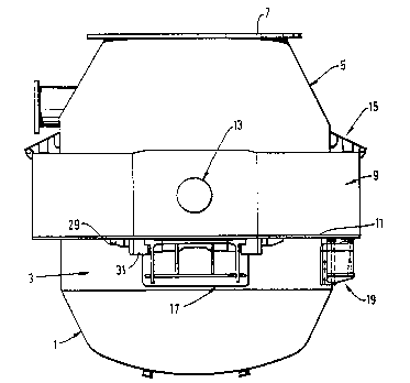
A basic oxygen converter vessel 1 comprises a
refractory lined met.al shell having a base portion, a central
cylindrical portion 3, a frusto-conical upper portion 5 and
an open top 7. The vessel is located within and supported in
~ a substantially circular
:
~ ~.
.
Wo91/18119 PCT/GB91/00782
2~3265
trunnion ring 9 having a bottom flange ll and a pair of
diametrically opposed outwardly extending trunnion pins `~
13. An annular slag shedder lS is connected to the top
of the trunnion ring and to the vessel to protect the
trunnion ring from molten metal. ~7'
Tho vessel i8 supported within the trunnion
ring by means which enable th- vessel to be removed
from the ring, if necessary. To this end, the support
for the vessel comprises a pair of suspension brackets
17 mount-d on the cylindrical part 3 of the vessel and
located one beneath ach of the trunnion pins 13. A -
guide bracket 19 is mounted on the cylindrical part of
the ~essel at a position substantially mid-way between
the brackets 17,
Referring particularly to Figur-s 2 and 4, it
can be ~een th~at each suspen~ion bracket 17 has a
vertical leg 21 which is ~haped to confor to th- outer
~urface of the vesseI ~l and which is secured to the
essel by means of bolts 23 which pass through the
~ ( ~
wall of the vessel and the vertical leg 21. At the
upper end of the vertical leg 21 there is a hor~zontal ~ -
leg 25 which has thickened blocks 27 fabr~icated into
each of~ its nds. The horizontal leg 25 is secured to
the vertical leg by ~tiffening plates 26.
To assemble the ring around the vessel, the
vessel is positioned in the ring with the suspension
plates 17 located beneath respective trunnion pins.
Wogl/l8ll9 PCT/GB91/00782
The upper faces of the blocks 27 on the brackets have
been dressed to ensure good bracket contact with the
bottom flange 11 on the trunnion ring A pair of stop
members 29 are welded or otherwise secured to the
underside of the flang- 11 A pair of claw members 31
are bolted to the flange ll by pre-stressed bolts 33
and each claw member has a projection whicb fits -~
underneath the portion 27 on the bracket As the bolts ~-
33 are tightened, the claw members 31 are clamped to '~
the underside of the flange 11 The claw member~ 31
are accuratély maehined so as to fit, with the minimum
of elearanee, between the braeket 17 and the stop
members 29
, . . .
Eaeh elaw, member i8 ~eeured to the flange 11
by an appropriate number of bolts and the flange member
.
11 may be strengthened, if neee-sary A minimum -~
~ clearance has to be provided between the elaw members,
'~ ; the braek-t and the stop memb-rs to allow for expansion
when th- vessel is filled with molten metal
Referring now to Figure 3, it ean be seen
that th- guide braek-t 19 is of similar eonstruetion to
the suspension brackets 17 in that it eomprises a
ertieal limb 21A and a horizontal limb 25A with
thiekened portions 2~7A at opposite ends of the
,~ ~
horizonta~l portion Stop members 29A are secured to
the underside of the flange 11 and packing members 31A
are located betwe-n the stop members 29A and the
, . , . ., ~ : . . . , .. , ., .... ,- ( ,
WO 91t18119 PCr/GB91/~0782
,
208326S
thickened portions 27A of the bracket 19.~ The packing
members are bolted into position with thè minimum of~`~
clearance between the braiifket and the stop members 29A
but the packing members do not have a claw which fits
- underneath the thickened portions 27A. The packing
members 31A prevent lateral movement from occurring
between the bracket 19 and the flange 11.
In all po-itionff~ of tllt, the w ssel is
rigidly f3upported within the trunnion ring by the `
suspension brackets and the suspenf3ion members. The
,~ guide bracket only ff~erves to locate the ves;3el within
'~ the trunnion ring. In this arrangement, therefor-, it
wlll be appreciated that there i~ a two-point
suspension of the vesse~ with an attitional guite means
between the ~effff3sel and the trunnion ring.
Although the invention has been specifically
e~emplified in relation to a ~basic osygen converter
~l vessel, it will be appreciated that the support
arrangement of this invention can be applied to other
types of furnace vessel.
f ~
I'`'` ~
::: :