Note: Descriptions are shown in the official language in which they were submitted.
2083~3~i `
B~C,K "G, ROUND _,O."F_Tl IE,. ,_I NV,,E,, NI,I ON,
The present invention i5 directed to a storage battery with a
coupling part for connection to a charging device with the coupling
part having at least plus-minus terminal contact pair on its o~uter
surface.
There are known electrically driven tools equipped with DC
drive motors where the driving energy is provided in storage
batteries. Such storage batteries made up of a number of
individual cells can be connected to the housing of the
electrically driven tool. The electrical connection of the storage
battery with the electric tool is effected by suitable coupling
parts. The mechanical mounting of the storage battery on the tool
is attained by clamping, latching or snap-in elements.
A storage battery is disclosed in US patent 4,576,880 where
several individual cells are connected in series. Such an
arrangement results in a storage battery voltage corresponding to
the sum of the voltages of all of the individual cells. The
~0 interconnected individual cells are connected to a plus-minus pair
of contacts located in an end region of the storage battery where
they can be tapped from the outside.
A mechanical coding device is located in the coupling part, so
that the known storage battery can be connected to electric tools
with the same battery voltage or to the correct poles. Two springs
are arranged in the housing of the storage battery and located
opposite one another for preventing an improper contact connection
-- 1
. .
. .
203~43~
of the plus-minus contact pair with the electric tool and also with
a charging device~
Coding apparatus in wide use involves one or several springs
disposed in the coupling part of the electric tool or the charging
device and engageable into one or several grooves in the coup~ing
part of the storage battery.
There are other coding apparatus where the storage batterY has
at least one spring engaging into at least one groove in the
electric tool or charging device. The coading apparatuses are
intended to prevent the use of improper storage batteries.
~ disadvantageous feature of plus-minus contact pairs disposed
on the housing of the storage battery is that there are different
manufacturers of storage batteries where the housings are similar
as far as shape and housing cross-section is concerned, whereby
they can be connected to electric tools and charging devices of
other manufacturers. The contact pairs, however, may have
terminals with different polarities.
If the polarity of the plus-minus contact pair of the storage
battery is interchangsd compared to the polarity of the plus-minus
contact pair on the electric tools or charging devices, such a
condition can lead to damage to the storage battery, the charging
device or the electric tool. h damaged battery can no longer be
charged. In the worst case the storage battery can explode due to
a short-circuit~
-- 2 --
" ' ' ' ' '"'~'" ' :' ' '' ' : '' ''' '-
. .: . .
- . ~.~. .~ : ,
: " . . ~, .:
. .
20~3~3~
SUMM~Ry OF THE INVENTION
Therefore, the primary obiect of the present invention, is to
provide a storage battery having a contact terminal arrangement
such that improper contact with the charging device or the electric
tool is avoided and ths safety of working personnel i5 assure~d.
In accordance with the present invention, the cross-sectional
area of the coupling part is divided centrally or symmetrically
into equal partial areas with one plus-minus pair of contacts
within at least one partial area.
With the plus-minus contact pair within one partial area no
faulty contacts can occur if the battery is connected with a
charging device or an electric tool when it is turned through 180~
in the circumferential direction of the axially extending housing.
Preferably, the storage battery has a coupling part with at
least two partial areas each having a symmetrically arranged
oppositely disposed plus-minus contact pair. The battery cells
within the storage battery are normally aligned in series and
connected electrically. By arranging several plus-minus contact
pairs, the battery cells in the storage battery can be divided into
several individual blocks with each block associated with a plus-
minus contact pair which can be tapped on the exterior of the
housing in the region of the coupling part.
The blocks can be designed in many ways~ Further, the
quantities of the individual cells within the individual blocks can
differ. ~s a result, voltages of different magnitudes can be
provided at the appropriate plus-minus contact terminal Pairs.
.. . . .... . ... . . .. . . .. . ..
: . - ~ . .
2 ~ d 3 ~
In another embodiment, the quantity of the individual cells in
each individual block can be equal. If such a storage battery is
used with an electric tool, the regulation or control electronics
can successively operate from the energy in the individual cells.
For instance, a storage battery has two blocks each Providing 1~2 V,
then the energy can be used in two different ways by a control with
an electronic arrangement installed in the electrically driven
tool. With both blocks arranged in parallel, an electromotive
force of 12 V with twice the capacity available for operating an
electrically driven tool, that is, the tool can operate twice as
long compared to one individual block with 12 V.
By connecting the blocks in series a voltage corresponding to
the sum of the voltages in all of the blocks can be obtained.
Where two blocks each of 12 V are arranged inside the storage
battèry, an electrically driven tool can be driven at a voltage of
24 V.
The contact terminals of the two plus-minus contact pairs are
advantageously symmetricallY arranged relative to tha bisection of
the area forming two partial areas of equal size and with respect
to a straight line extending perpendicularly to the line bisecting
the total area and passing through the center of the partial area.
Due to the symmetrical arrangement of the plus-minus terminal
contact pairs, the wiring of the individual blocks with the
associated plus-minus contact pairs can be identical within the
storage battery. These are considerable manufacturing ad~antages
which affect the manufacturing costs of the storage battery.
', : ' ' " ' '' ' ' '
.,. . .... . . . ~ .
. ~ ..,. ,, ., ~ .
2ag3~3~
Preferably, the charging device of the storage battery has a
coupling part where the cross-sectional area of the coupling part
is subdivided centrally or symmetrically into equal partial areas
with a plus-minus terminal contact pair located within at least one
of the partial areas.
Because of the disposition of the plus-minus terminal contact
pair in one partial surface, it is not necessary to pay attention
how the battery is oriented when it is inserted into the charging
device. Since the plus-minus terminal contact pair is arranged in
lo only one partial area, no improper contact can be established. In
a preferred arrangement, a charging device has at least two partial
areas each having one plus-minus pair of terminal contacts arranged
centrally opposite one another.
By the central or symmetrical arrangement of the plus-minus
terminal contact pairs, it is possible to charge a storage batterY
having at least one block. In such a char~ing device having a 12
V charging voltage, there is the advantage that it can be
economically constructed with low cost components and with low
voltage resistance requirements specified for the active components
of the charging device.
The charging of the individual blocks of the storage battery
is effected consecutively. If a charging device with only one
single plus-minus pair of terminal contacts is available, then the
battery must be removed from the charging device betwsen each
charging step or it must be separated from the coupling part of the
charging device and turned around the axial direction until the
. .
. . -:
... . - : ~.
. , . . , ~,............ .
" . .
, .. -
20~3~
next plus-minus pair of contacts with the battery are aligned
opposite the plus-minus pair of the terminal contacts of the
charging device~ Next the battery is again connected to the
charging device~ The completion of the charging of one block can
be indicated by a signal.
In so-called quick-charge devices, the central arrangement of
the plus-minus terminal contact pairs is advantageous, since in the
charging device with ssvsral plus-minus pairs exposed consecutlvely
to 12 V charging voltage, care does not have to be taken how the
battery is inserted into th~ coupling part charging device. The
proper connection with the contact is always assured.
Preferably, the charging device is characterized in that the
contact of two plus-minus pairs of terminal contacts are
symmetrical ly arranged relative to the median dividing the partial
areas of equal size and with respect to a straight line extending
through a center of the partial areas and disposed perpendicular to
the median.
Due to manufacturing reasons relative to the fabrication of
the coupling part of the charging deviceJ the above-mentioned
symmetrical arrangement of the plus-minus pairs of terminal
contacts is preferred.
This results in more uniformly distributed voltages during
charging.
Two different charging devices are available affecting the
charging duration of the storage batteries of equal capacity. The
"normal" charging device differs from the "quick" charging device
-~ ; - - ,
: :: . ..,, . : : ~
: : .: ,: , :,
~ ~ ~ 3 ~
by having a charging period which i5 SiX times longer. The
"normal" charging device can be manufactured more economically due
to the simpler electrical components used.
Storage batteries suitable for use in "quick" charging devices
have a different chemical construction than the batteries~ in
"normal" charging devices. If a storage battery suitable for a
"normal" charging device is inserted into a "quick" charging device
it would result in damage to or explosion of the battery.
To prevent such an occurrence, it is possible to attach a
blocking arrangement at the storage battery in the region of the
coupling part for preventing the insertion of batteries suitable
for "normal" charging devices into "quick" charging devices.
The charging device howeverl must have the recess for
accepting the blocking arrangement, whereby the storage battery can
be inserted into the "normal" charging device. This feature does
not impede the insertion of the battery for "quick" charging
devices into a "normal" charging device.
The various features of novelty which characterize the
invention are pointed out with particularity in the claims annexed
to and forming a part of this disclosure. For a better under-
standing of the invention, its operating advantages attained by its
use~ reference should be had to the drawing and descriPtive matter
in which there are illustrated and described preferred embodiments
of the invention.
., .,, ., , . ,,, , . ~ .. ,. . .......... . ~ . . .... . . ... ~ .
: . . - . . . . :,
.-. . . ..
3 ~
BRIEF DESCRIPTION OF THE DRAWING
_ ~.. ~.. _.. --.. _ .. ~.. . .. ~ _.. _ . _.. __ _ .. _ _.. __
In the drawing:
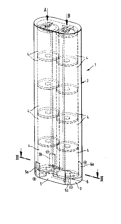
Fig. 1 is an elevational view in perspective of a storage
battery, with two plus-minus contact terrninal pairs, embodying the
present invention;
Fig~ 2 is a cross-sectional view of the storage battery shown
in Fig. 1 taken along the line II-II;
Fig. 3 is a plan view of a charging device having a coupling
part with a charging recess having two plus-minus contact terminal
pairs;
Fig. 4 is a sectional view corresponding to the sectional view
in Fig. 2 in a storage battery with one plus-minus contact terminal
pair; and
Fig. 5 is a plan view similar to that in Fig. 3, however,
where the charging recess of the charging device has one plus-minus
contact terminal pair~ -
DETAILED DESCRIPTION OF THE INVENTION
In Fig. 1 an axially extending storage battery 1 has two
blocks A, B each containing five individual cells 4 electrically
connected in series in each block. The storage battery 1 has an
axially extending housing 2 with a coupling part 3 at one end. Two
plus-minus contact terminal pairs 5a, 5b, 6a, 6b are located in
the coupling part 3 connected to the blocks ~, B and arranged to be
tapped from the outside of the housing 2.
Fig. 2 shows the storage battery 1 with the two plus-minus
contact terminal pairs 5a, SbJ 6a, 6b arranged symmetrically
-- 8 --
- ' ' - '
3 ~
opposite one another with each plus-minus contact terminal pair 5a,
5b, 6a, 6b disposed in a separate partial area 5, 6 of the cross-
sectional area of the housing extending transversely of its axis.
The number of individual cells 4 in each block Q, ~ can be equal or
different. In each case the sum of the voltages of blocks ~A, B
equals the voltage of the storage battery 1.
~ s an example, the storage battery 1 has two 12 V blocks.
Such a storage battery can power electrically driven tools to be
operated at 12 or 24 V.
By means of internal regulation or control electronics housed
in the electrically driven tool the energy can be utili~ed in
series. As a result, a voltage of 24 V is available. If both
blocks are electrically wired in Parallel, a voltage of 12 V but at
twice the capacity is available~
Fig. 8 displays a charging recess in a charging device
containing a coupling part 10a, with its cross-sectional surface
subdivided into two symmetrical and equal partial areas with one
plus-minus contact terminal pair 7a, 7bz 8a, 8b assigned to each
partial area 7, 8. The device 9 required for the charging
apparatus can provide a voltage of 12 V. Due to the low charging
voltage of 12 V the components of the device 9 can be designed for
12 V~ ~ccordingly, the charging device 9 can be economically
manufactured, because the individual components cost considerablY
less than the components for a charging device 9 designed for a
charging voltage of 24 V.
.: . .
. : . .
: ~ ' .. . i
:; . .. ~ . :
2~g3~3t~
When the charging process for the 12 v block ~ in a 12 v
charging device is completed, the other 12 V block B is charged~
The completion of the charging procsss of the first block ~
can be indicated by a signal, for instance a lamp or a sound
signal. By turning the storage battery 1 manually in ~the
circumferential direction, that is, transversely of the axial
direction, the next block B can be placed in position for charging.
The charging device 9 can be arranged so that plus-mlnus
contact terminal pairs 7a, 7b, 8a, 8b are disposed in the charging
10recess lOa of the coupling part 10 with the quantity of the contact
terminal pairs in the charging device 9 being equal to the number
of contact terminal pairs 5a, 5b, 6a, 6b located in the housing 2
of the storage battery 1. In such an arrangement of a more
expensive charging device 9 it is unnecessary to turn the battery
manually in the circumferential direction during the charging
proces~ The blocks A, B in electrical connection with the
individual plus-minus terminal contact pairs 5a, 5b, 6a, 6b are
charged consecutively by means of an internal electronic charging
arrangement.
20~ccordingly, a 24 V storage battery, not illustrated, can be
divided into three blocks, whereby the chargins device provides a
charging voltage of only 8 V. By appropriate electric connections
in series of the individual blocks in the electrically-driven tool,
a voltage of 24 V is available.
In Fig. 4 the cross-sectional area of a coupling part 13 of
a storage battery 11 is divided symmetrically into two equal
-- 10 --
~' ', ' ' ' ::
,.'.''~
, . ~
2~8~3~
partial areas 15, 16 with one plus-minus contact terminal pair 15a,
15b. In this embodiment, the plus-minus terminal contact pair 15a,
15b is disposed in the partial area 15. Each individual cell of
the storage battery 11 has a voltage of approximately 1.2 V when
used in electrically driven tools having an energy of 1.2 ~to 4
Ampere hours.
In Fig. 5 a charging device 19 is shown with a charging
section 20 containing a coupling part 20a with its cross-sectional
area dividsd into two symmetrically equal partial areas 17, 18 with
a plus-minus contact terminal pair 17a J 17b located in one of the
partial areas 17. The charging device 19 has a housing 20
characterized by high stability.
The charging device 9 has a circuit part with a transformer
and a rectifier portion for producing a DC voltage as a supply
voltage.
While specific embodiments of the invention have been shown
and described in detail to illustrate the inventive principles, it
will be understood that the invention may be embodied otherwise
without departing from such principles.
-- 11 --
. . .. .. .... .. . . .... . . , .. , .. .. ~ .. . . .. , ... . ,, . . . .. . ., . ,. .... , . ~, ., . ,.. , ~,, ,. ,,, .",
. .
. , ~. . . .
' '; .' : ~. ' ~ :