Note: Descriptions are shown in the official language in which they were submitted.
2083636
1 BACKGROUND OF THE INVENTION
Field of the Invention
The present invention relates to an improve-
ment in a bicycle frame and, more particularly, to a
bicycle frame which can absorb shocks during running
to provide a more comfortable ride and which exhibits
improved durability and running performance, thus
attaining improved safety of ride.
Description of the Prior Art
A bicycle has been designed in such a way
that impact is eased by a front fork which is bent in
response to any shock to absorb it. Because the
provision of a suspension system has been considered
to be incompatible with the basic requirements for
making a bicycle lighter and more rigid, the suspension
system has not been employed so far. Recently, however,
the bicycle materials have been made lighter and, in
addition, more comfortable ride is greatly demanded.
According to the remarkable popularity of mountain
bicycles (MTB), moreover, various kinds of bicycle races
have become popular, including offroad and downhill
rides. Thus, to absorb shock caused by rough roads is
greatly demanded.
Recently, researches have been carried out
-- 1 --
-
2083~36
1 on bicycles in which shocks are absorbed by the front
fork or by a frame head portion incorporating a
reinforced urethane resin therein, as well as by a
suspension provided in the saddle.
Nevertheless, a defect of these various
suspensions is that they only absorb shocks to which
the front wheel or the saddle portion is subjected, so
that the shock absorption has been undesirably limited.
The shock absorption capability of bicycles on the
rear wheel side is the most important factor in the
view points of performance and comfort of ride. There
have been no bicycles which possess such a capability
and a high rigidity. The conventional bicycles have
been greatly improper particularly in respect of the
absorption of shocks on both front and rear wheel sides
during offroad rides.
SUMMARY OF THE INVENTION
The present invention provides an improvement
in a bicycle frame of the type that has a bracket lug,
a seat lug and a head lug, the bracket, seat and head
lugs being linked together by a seat tube, an upper
tube and a lower tube to form a substantially triangular
frame structure. The improvement according to the
present invention comprises a chain stay disposed
rearwardly of the triangular frame structure and
pivotally connected at an end to the bracket lug; a
substantially triangular link having a first apex
20836~6
1 formed between its long and short sides, a second apex
formed between the long side and a medium side and a
third apex formed between the medium and short sides,
the link being pivotally connected at a point adjacent
the first apex to the seat lug such that the long side
is directed toward the head lug; a shock absorbing
cylinder assembly including a cylinder connected at an
end to the upper tube and a cylinder rod normally
urged to project outwardly from the cylinder and having
a free end pivotally connected to the triangular link
at a third point adjacent the third apex; and a rear
fork member extending between and pivotally connected
to the triangular link adjacent the second apex and the
chain stay adjacent a rear axle support thereof.
As pointed out above, in the bicycle frame
according to the present invention, the triangular
link having long, medium and short sides is pivotally
connected at its first point to the seat lug such that
the long side is directed toward the head lug. The
triangular link is also pivotally connected at its
second point to an end of the rear fork member with
the other end thereof pivotally connected to the chain
stay adjacent the rear axle support thereof. The
triangular link is further pivotally connected at the
third point to the free end of the cylinder rod of the
shock absorbing cylinder assembly with the cylinder
thereof connected to the upper tube of the triangular
frame structure of the bicycle frame. Accordingly,
2083636
1 when the rear wheel is subjected to a shock, the chain
stay is swung about the pivot point on the bracket lug
so that the rear axle support is raised.
Accordingly, the rear fork member follows the
upward movement of the rear axle support to urge the
second point of the triangular link toward the shock
absorbing cylinder assembly, so that the triangular link
is rotated about the pivot point on the seat lug against
the force of the shock absorbing cylinder assembly to
allow the second point of the triangular link to be moved
toward the shock absorbing cylinder assembly. When the
angle between the rear fork member and a line
interconnecting the pivot point of the triangular link on
the seat lug and the second point on the triangular link
is increased beyond 90 degrees, the angle of rotation of
the triangular link caused by the movement of the rear
fork member is increased to increase the displacement of
the cylinder rod of the shock absorbing cylinder
assembly. This will mean that the axle load relative to
the travel of the rear axle is changed non-linearly to
provide a so-called "progressive effect", whereby
sufficient suspension and high rigidity are maintained
and a comfortable ride is provided without power loss.
The above and other objects, features and
advantages of the present invention will be made more
apparent by the following description with reference
to the accompanying drawings.
4 -
.....
208~636
1 BRIEF DESCRIPTION OF THE DRAWINGS
Fig. 1 is a side elevational view of an
embodiment of a bicycle frame of the invention;
Fig. 2 is an enlarged fragmentary elevational
view of the frame, illustrating the locus of movement
of a triangular link; and
Fig. 3 is a graph showing the relationship
between the upward movement of the rear axle bearing
(wheel travel) and the reaction force (axle force)
directed downward from the rear axle support.
DESCRIPTION OF THE PREFERRED EMBODIMENT
A preferred embodiment will be described
hereinunder with reference to the drawings. Referring
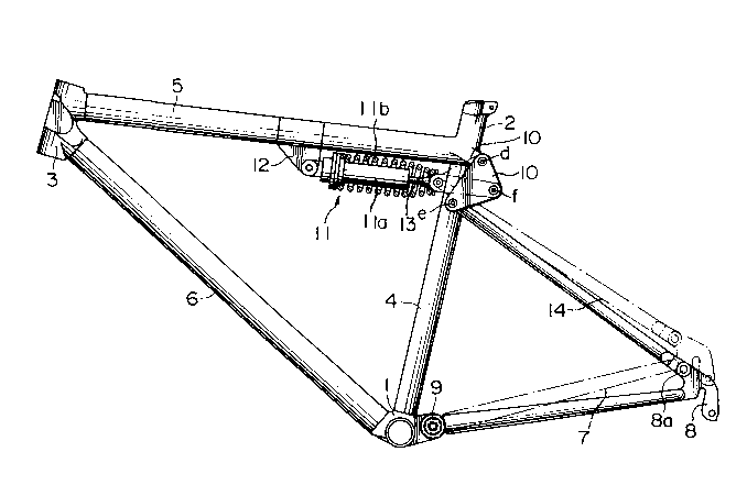
to the drawings, a bicycle frame embodying the present
invention includes a bracket lug 1, a seat lug 2, a head
lug 3, a chain stay 7, a triangular link 10, a shock
absorber cylinder assembly 11, and a rear fork member
14. The bracket lug 1, the seat lug 2 and the head lug
3 are linked by a seat tube 4, an upper tube 5 and a
lower tube 6 to form a triangular structure. The chain
stay 7 and the rear fork member to be described later
are connected to the triangular structure to complete a
bicycle frame.
The chain stay 7 is pivotally connected at
one end to the bracket lug 1 by means of a pin 9 and
integrally connected at the other end to a rear axle
support (rear fork end) 8. The rear axle support 8 is
-- 5
-
2~836~6
l pivotally connected to the rear fork member 14 by
means of a pin 8a. The triangular link lO comprises
a triangular plate member having a long side a, a
medium side _ and a short side c. The long side a
and the short side c form therebetween a first apex
d. Likewise, a second apex e and a third apex f are
respectively formed between the long side a and the
medium side _ and between the medium side _ and the
short side c. The triangular link lO is pivotally
connected at a point adjacent to the first apex d to the seat
lug 2 such that the long isde a is directed to the shock
absorber cylinder assembly 11, i.e., to the head lug 3.
The shock absorber cylinder assembly ll
includes a hydraulic cylinder lla which is pivotally
connected at one end to the upper tube 5 by means
of a mounting bracket 12 and a cylinder rod 13 which
is urged outward to project from cylinder lla. The
outer end of the cylinder rod 13 is pivotally connected at a
point adjacent to the third apex f of the triangular link 10.
A compression coil spring llb is disposed around the cylinder
lla and the cylidner rod 13 and extends between the trinagular
link 10 and a flange on the cylidner lla. The upper end of
the rear fork member 14 is pivotally connected at a point
adjacent to the second apex e of the trinagular link 10 so
that the chain stay 7 swings counterclockwise as indicated by
broken lines in Fig. 1 when a rear wheel is subjected to a
shock. Consequently, the second apex e of the trinagular link
10 roates clockwise about
f 6
,~
2083636
1 the first apex d and, simultaneously, the cylinder rod
13 connected to the third apex f is forced back into
the shock absorber cylinder assembly 11 against the
outward urging force thereof, whereby the shock is
absorbed.
A description will now be made of a pressing
torque which acts on the cylinder rod 13. When the
rear wheel is subjected to a shock, the chain stay 7
rotates counterclockwise about the pin 9 of the bracket
lug 1 in accordance with a movement of the rear axle
support 8 to a position shown by broken lines in Fig. 1,
allowing the rear axle support 8 to be lifted upwards.
Accordingly, the rear fork member 14 urges the second
apex e of the triangular link 10 towards the shock
absorber cylinder assembly 11 to rotate the triangular
link 10 such that the second apex e of the triangular
link 10 is moved from the position e through positions
el and e2 to a position e3 towards the shock absorber
cylinder assembly 11 around the supporting part (the
first apex d) of the seat lug 2, against the pressing
force exerted to the triangular member 10 by the
cylinder rod 13 and the spring llb.
In correspondence with the movement of the
second apex e, the long side a moves as al-a2-a3, the
medium side b as bl-b2-b3, and the short side c as
cl-c2-c3. The third apex f consequently moves
progressively as fl-f2-f3, to thereby press the cylinder
rod 13 along its longitudinal axis 13a. Therefore the
2083636
1 shock absorber cylinder assembly 11 is progressively
compressed.
At this moment, a substantially right angle
is formed between the line interconnecting the second
apex e and the supporting point (the first apex d) of
the seat lug and the longitudinal axis of the rear fork
member 14, as shown by solid lines in Fig. 1. Beyond
this time point, the angle of rotation of the triangular
link 10 caused by the rear fork member 14 becomes
greater, so that the movement of the cylinder rod
increasesconsequently. Further, the upward movement
of the chain stay 7 is controlled due to "progressive
effect" as shown in the curve of the graph shown in
Fig. 3 indicating the relation between the upward
movement of the rear axle support 8 (wheel travel) and
the reaction force (Axle-Force) directed downward from
the rear axle support 8. Thus, suspension and rigidity
are sufficiently maintained to provide comfortable ride
without power loss.
As will be understood from the foregoing
description, the present invention provides a bicycle
frame comprising a bracket lug, a seat lug and a head
lug linked by a seat tube, an upper tube and a lower
tube to form a triangular frame structure, wherein a
chain stay is provided rearwardly of the frame
structure and pivotally connected at its one end to
the bracket lug, a triangular link having a first apex
formed between long and short sides, a second apex
~, - 8 -
208~636
1 formed between the long side and a medium side and a
third apex formed between the medium and short sides,
the triangular link being pivotally connected at the
first apex to the seat lug with the long side directed
toward the head lug, a shock absorbing cylinder assembly
has an end supported by the upper tube and includes a
cylinder rod normally urged to project outward, the
triangular link being pivotally connected at the third
apex to a free end of the cylinder rod; and a rear
fork member is provided between the second apex of the
triangular link and a portion of the chain stay adjacent
a rear axle support. Consequently, the present
invention offers the following advantages.
When the rear wheel is subjected to a shock
during running, the chain stay swings about the
supporting part of the bracket lug, allowing the
rear axle support to be raised upward. Correspondingly,
the rear fork member urges the second apex of the
triangular link towards the shock absorber cylinder
assembly, so that the triangular link is rotated about
the support part of the seat lug to causes the third
apex to move towards the shock absorber cylinder
assembly against the urging force exerted to the
cylinder rod. The angle of rotation of the triangular
link caused by the rear fork member is increased when
the angle formed between the rear fork member and a line
interconnecting the first and second apices d and e of the
triangular link has been increased beyond 90. The
g
2083~36
l movement or displacement of the cylinder rod is
therefore increased to produce an effect known as
"progressive effect", to advantageously control upward
displacement of the chain stay, whereby sufficient
suspension and high rlgidity are maintained to provide
comfortable ride without power loss.
By virtue of the use of the triangular link,
the rear wheel load is efficiently widely distributed.
Furthermore, because the triangular link is pivoted to
a portion of the frame adjacent the point where the
seat tube and the upper tube are connected together,
i.e., to the seat lug, the present invention is also
capable of ensuring sufficient transverse rigidity for
a bicycle frame which usually lacks transverse
stability.
-- 10 --