Note: Descriptions are shown in the official language in which they were submitted.
f
' ~ 2A8~898
-1-
SAUSAGE DISPENSING ADAPTER
This invention relates to a device for dispensing
sealant.
The use of sealing materials to fill voids in
various kinds of constructions is widely known, especially in
building construction. These sealing materials, also known
as sealants, are used to keep undesirable environments in
their proper place, such as rain, wind or heat on the outside
of buildings. These sealants are applied in a variety of
forms and from a variety of apparatuses. The apparatuses
used by large building construction companies or users of
sealants, such as in the manufacture of appliances or
automobiles, to dispense sealant materials into voids, may be
very sophisticated and expensive. For many applicators of
sealants, the use of a simple caulking gun to dispense
sealants is the method of choice. As the use of sealants
increased, the p,~ckagiv~; for these materials changed and over
several years, cartridges were the primary way to package
sealant. The cartridga_s were most often designed with a
nozzle through which a sealant composition could be extruded
into a void or location requiring sealing. These cartridges
were adapted to be loaded into devices equipped with
mechanisms to pu~~h the sealant composition out of the
cartridge package. Such. devices are commonly called caulking
guns or dispensing guns. These cartridges, depending on the
kind of storage required for the sealant composition, were
made from paper, foiled lined paper, plastic and various
kinds of molded and laminated constructions. A conventional
sealant cartridge for s.ealants which cure by exposure to
moisture, thus requiring protection from moisture during
- -~ 2483898
-2-
storage, is a single integrally molded cylindrical body
having a nozzle which is used as an exit orifice and a
plunger is disposed within the cylindrical body. Sealant
composition is contained in a cavity defined by the face of
the plunger in the discharge direction and the inner wall of
the molded cartridge. The sealant composition is discharged
through the exit orifice upon application of a force to the
plunger by an extrusion device employing mechanical or
pneumatic means. After as much of the sealant composition as
possible is discharged :from~the cartridge, it is discarded,
These cartridges are discarded in landfills which is
environmentally ,undesirable because the volume of the
cartridge is large. To reduce the amount of waste caused by
the disposal of 'the cartridges, the manufacturers of the
sealant compositions an<i packages developed so called
"sausage packages" for the sealant compositions. These
sausage packages use much less material for the package,
produce low amounts of solid waste and can be made air and
moisture imperme~ible, sa that they can c.antain sealant
composition which is sensitive to moisture. These sealant
containing sausaF;e packages c_an be inserted into some kinds
of dispensing cartridges or caulking gun barrels which
permits discharges of sealant composition. The waste created
by the spent sau:>age slkin is considerably lower than that
created by the d~:scard of the cartridges. However, although
the amount of package waste may be reduced, the dispensing
devices need to tre cleaned each time a different color
sealant is used or before it is set aside until required for
the next use, such as o v ernight .
Sealant: dispensers which are adapted for use with
the sausage package cornprise a gun barrel with a nozzle
assembly forming an integral part of the barrel or releasably
attached to the ~~arrel with suitable securing means, a
C
2~8~89~
-3-
piston disposed within the barrel and mechanical or pneumatic
means for actuating the piston located at the opposite end of
the barrel which is operated using a trigger mechanism.
Salmon in French Patent No. 930,316, granted
August 4, 1947 anal pub7_ished January 22, 1948, to Expandite
Products, Limited teaches a process and device for applying a
composition in a seam or in a fissure. A caulking compound
is hermetically sealed in a cylindrical section of a package.
The material for the package is preferably a transparent
sheet of cellulose acetate. One end of the package is cut by
scissors so as to allow the caulking compound to be forced by
a plunger of a caulking pistol through an orifice. The end
of the package ma;y be cut either before or after introducing
the package charge into the pistol barrel. After forcing the
charge of the pistol through the open end of the package
while at the same time leaving the package in the barrel, the
packaging is removed from the barrel by removing a cap and
destroying it and introducing a new charge. The pistol
nozzle is attached to a <:ap concave on the inside which
covers the end of the barrel and the end of the pistol
plunger is convex so as t:o have a surface complementary to
the concave surface of the cap so as to assure integral
expulsion of the packaging composition. With the device described
by Salmon it would be: difficult to change kinds of sealants
without substantial effort to clean the pistol barrel and
nozzle when different kinds of sealant composition are used
sequentially.
Seng in French Patent No. 1,127,069, granted on
August 6, 1956 and published on December 7, 1956, teaches a
distributor for viscous products such as greases and plastic
products which can be polymerized cold before their
polymerization. The distributor includes a cylindrical body
208389
-4-
sealed by a thre<ided cover and by a threaded piece to which
the distribution adjustment is attached. Inside a body, a
piston is mounted which is one piece with a rod equipped with
a handle and thi:o piston moves in this body under the effect
of a spring. The: piston can be kept in place when it
encounters the effect of a spring by means of a jam lever
which may penetrate int=o a cover through an opening which
acts on the point of articulation and which is equipped with
a drilled hole through which the rod passes with a lever
being jammed obliquely onto this rod by means of the spring.
The piston rod ha,s an extension which projects from the outer
side of the piston and against which a collar equipped with
bosses can be kept by means of a screw. A sealing piece is
also equipped with an external cylindrical throat which
causes there to be a cylindrical recess with the internal
wall of the body. A sack containing viscous product is
placed into a cavity of the distributor and jerking movement
is supplied by means of the jamming device which acts against
the piston rod and which releases this rod under the effect
of the operator's hand. The viscous material is contained in
a casing in the form of .a sack placed into the distributor
body after removing the distribution adjustment and which is
open after this installation. The piston is then one piece
with a prominent collar equipped with vents which communicate
with the back of i~he piston by means of holes made in this
latter and which rests on the bottom of this casing. This
distributor is a <~omplicated device and not suitable for
multiple kinds of product: without extensive clean up.
A sealant dispensing cartridge on the market which
employs sealant sausage packages comprises a self supporting
cylindrical .sleeve:, an end cap and a plunger disposed within
the sleeve,andthep7.unger, inner wall of the sleeve and the end
cap provide a cavity for the sealant sausage package. The
C
_._.~.. ..~_._ _ _,_. ~m __.
2oa3898
-5-
sleeve is adapted at one end to releasably receive the end
cap. The main body of the plunger comprises a cylindrical
surface in sliding contact with the inner wall of the sleeve
and faces, one o:E which is substantially flat against which
force is brought to bear from a gun mechanism,andtheother
face, in the discharge direction, provides attachment means
for fixing thereto a pressuxe relief spring which comprises a
disc with diametrically opposed tongues, slightly larger in
diameter than they main body of the plunger and is in
frictional engagement with the inner wall of the sleeve. A
plurality of holes run through the main body of ~e plunger and
the pressure release d~:sc ,thus creating a pressure equalizing
effect as the plunger i_s driven along the sleeve.
Extrusion devices employing such a cartridge
generally comprise a framework in which the cartridge is
supported and means for supplying a force to the plunger such
as a piston which is acauated by mechanical means using a
trigger mechanism, for example, a skeleton gun.
Segatz in U.S. Patent No. 4,840,293, issued
June 20, 1989, assigned to ARA-Werk Kramer GmbH & Co.
describes an apparatus for discharging a bead or strand of
pasty material fr~~m a de:Eormable tubular container such as a
tubular bag havin~~ a bag--loadable cylinder with a front face
pointing in a discharge direction, the front face having a
central opening a:Ligned with a nozzle connection of the
tubular bag. A substantially piston-like pressure member is
axially displaceable against the tubular bag in the cylinder.
In order to avoid drooling and dribbling of material through
the nozzle after interruption of the discharge process and
also to prevent jamming o~f the edges of the tubular bag, the
pressure member ha.s a pressure relief spring supported on the
wall of the cylinder and cooperating therewith, the spring
having spring tongues directed obliquely forward around the
208389
-6-
deformable bag. The apparatus is used to extrude sealant
material encapsulated :in a sausage package and comprises the
cylinder adapted to receive the sausage package and a plunger
which is provided with a pressure release spring attached to
one face. The sF~ecification states that where pneumatic
means are provided for moving the plunger, an elastic closure
having a diameter slightly larger than the diameter of the
main body of the plunger should be provided to seal the
plunger against the inner surface of the cylinder. The
elastic closure is attached to a face of the plunger opposing
the face connecting they pressure release spring. While this
apparatus is satisfactory in many respects, it is unsuitable
for use in both mechanically operated and pneumatic extrusion
devices without necessary modification of the plunger. Such
modification requires the dismantling and reassembly of the
apparatus, a time consuming process which is an inconvenience
to an operator.
It is an object of this invention to provide an
adapter which can dispense sealant composition from a sausage
package, reduces cartridge and sealant waste, is easy to
clean-up, is environmentally acceptable, is easy to use and
is economical. It is also a further object that the adapter
be suitable for u;se in vmechanical and pneumatic dispensing
apparatuses and requires no adaptation when changing from a
mechanical to a pneumatic: dispensing apparatus.
This invention relates to an adapter for dispensing
extrudable material contained ina collapsible, flexible,
cylindrical sausage-shaped skin package from an extrusion
device designed for dispensing such material from a rigid
cylindrical tube, said adapter comprising a rigid walled
cylindrical tube having an inner wall diameter approximating
the diameter of the skin package and an axial length
sufficient to accammodat:e the length of the skin package and
__ 2083898
_,_
at least a portion of the axial length of a circular
dispensing plunger, said dispensing plunger having an outer
circumferential mall a~.zd first and second ends, the outer
circumference of at least the first of said ends having a
diameter approximating the inner wall diameter of the
cylindrical tube for sliding, scraping contact therewith, the
circumferential wall of the plunger intermediate to its ends
having a diameter less than the diameter of said first and second ends to
reduce friction a.s the plunger is moved axially, said first
plunger end also having a circular recess located between its
movement axis and. its periphery for collecting the sausage
skin as material is discpensed therefrom by movement of the
plunger and having an axially extending cror~m portion
protruding beyond the plane encompassing the end of the outer
wall of the plunger; the second end of the plunger being shaped to
allow application of force to cause said plunger to slide
through the cylindrical tube.
This invention also relates to a method of
dispensing an extrudable material from a container comprising
applying a force to one end of a dispensing means and forcing
the extrudable material from an orifice to a desired
location, wherein the improvement comprises inserting a
sausage package of an extrudable material into an adapter as
described above between the adapter plunger and the removable
nozzle base and thereafter applying a force to the adapter
plunger.
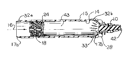
Figure L is an exploded isometric view of a
sausage-shaped skin package in an adapter in a dispensing
gun.
Figure :Z is a partial cross-section view of the
adapter containing a savusage-skin package showing extrudable
material being di:~pensed from the nozzle tip orifice and the
_. 283898
-8-
package skin ~~ollapsing as the dispensing plunger is moved
toward the nozzle base.
Figure 3 :is a crumpled wad of protective skin from
the sausage-shaped skin package after extrudable material has
been dispensed.
Figure 4 is an exploded view of cutaway cross
section showir,~g a locking means for the cylindrical tube and
removable nozzle base.
Figure 5 is a partial cross-section of a cylindrical
tube with two tapered ends.
Figure 6 is a partial cross-section of a cylindrical
tube with one 'tapered end.
Figure 7 is a perspective view of the removable
nozzle base.
Figure 8 is a one-half cross-section of the
removable nozzJ.e base.
Figvs-a 9 i:a a view from the second end of the
circular dispersing plunger.
Figure 10 i.s a one-half cross-section of the
circular dispensing plunger.
Figure 11 is a perspective view of the circular
dispensing plunger.
List of reference numbers and description
e:Ktrudab:le material
I1 collapsible, flexible, cylindrical
saiusage-shaped skin package
12 extrusion device
13 rigid walled cylindrical. tube
14 inner tube wall
outer tube wall
16 movement: axis
17 tube end
18 circular dispensing plunger
A
2Q 83898
-9-
19 male portion of locking means
20 femal portion of locking means
21 outer circu:m.ferential plunger wall
22 first plunger end
23 second plunger end
24 circular recess
24a circular recess on the first plunger end
24b circular recess on the second plunger end
25 axially extending crown portion
27 concentric circular ribs
28 removable nozzle base
31 rernovable nozzle tip
32 tapered surface on tube end
33 ini=ernally tapered flange
34 th~__°eaded male portion for attachment of
rennovable nozzle tip
35 funnel shaped portion
36 circular base of nozzle base
37 sti-uctur;~.l. ribs
38 re:~train_ing plate portion
41 ejector pi.n pad
42 orifice
43 protective skin
Rigid walled cylindrical tube 13 of the adapter of
this invention, a.s shown. in Figures 1, 2, 5 and 6, can be
made of any suitable durable self supporting material capable
of withstanding pressures associated with the extrusion
process, for example, metals such as stainless steel and
aluminum or plastics such as polyvinylchloride,
polypropylene and polyethylene. It is preferred that tube 13
and the other parts of the adapter of this invention be made
of plastic materials, especially recyclable plastic material
such as polyethylene. The most preferred material is one
which is translucent in: optical properties. This
C
~._ _.~_.~,~_._. _ __
. _ 2083898
-lo-
translucent ciharacteristic allows an operator of an extrusion
device containing a sausage skin package to see the amount of
extrudable mal:erial remaining in the sausage package as well
as read at least the large print on the sausage package.
Tubes 13 can be machined, molded or extruded into
the correct shape and dimensions to be fitted into
conventional E~xtrusi:on devices, such as caulking guns as
illustrated by extrusion device 12 in Figure 1. Inner tube
wall 14 and outer tube wall 15 are uniformly smooth. Tube 13
is designed to receive a collapsible, flexible, cylindrical
sausage-shaped skin package 11 containing extrudable material
10. An extrusion device 12 can be used to dispense
extrudable material 10. The diameter of inner tube wall 14
approximates t;he diameter of skin package 11 and tube 13 and
has an axial length sufficient to accommodate the length of
skin package 1:1 and at: least a portion of the axial length of
a circular dispensing plunger 18. The outer circumference of
plunger wall 2:L of plunger 18 has a first plunger end 22 and
a second plunger end 23. The outer circumference of at least
the first plunger end 22 has a diameter approximating the
inner wall diameter of tubeI3 and provides a sliding and
scraping contact with the inner tube wall 14. The outer
circumferential wall 21 of plunger 18 intermediate to its
ends has a diameter less than the diameter of the plunger
ends 22 and 23. The outer circumferential plunger wall of
the plunger is illustrated by Figures 10 and 11. The outer
circumferential plunger wall 21 has a curved concave surface
in the preferre~~ embodiment, but this surface could also have
other shapes, ~;uch a;; a "V-shape" where the point of the "V-
shape" would be at a point on the outer circumferential wall
of the plunger :intermediate to its ends. This shape of the
outer circumfere~ntial wall of the plunger is significant to
permit the plunger to slide within tube 13 without binding,
,_ ___._...._
s.... 2883898
-11-
to act as a scraper to keep the sausage package skin and any
extrudable mater.Lal from getting to the side of the plunger
which is opposites the compartment containing the skin
package. The ends of the plunger are flexible enough to
maintain a tight seal and because the shape results in a low
friction between the outer circumferential plunger wall and
inner tube wall l_4, they plunger moves easily along the axial
length of tube 13~. Other shapes were tried but resulted in
the skin of the sausages package binding at the interface
between the outer' plunger wall and the inner tube wall. This
binding resulted in uneven discharge of the extrudable
material or required too much pressure to extrude material
from the sausage package.
Plunger 18, a.t least at the first plunger end, also
has a circular recess 2:4 located between its movement axis 16
and it s periphery . As illustrated in Figure 10, both ends of the plunger
have recesses,
as shown by numerals 24a and 24b, respectfully. Circular recess 24 collects
protective skin 43
of sausage skin package 1.1 as extz~udable material 10 is dispensed from
orifice 42 by movement
of the plunger toward the nozzle end of the adapter along movement axis 16.
The sausage skin
folds in this recess and binding is avoided as the plunger is forced along the
tube's axial length.
Plunger 18 also has an axially extending crown portion 25 protruding beyond
the plane
encompassing the end of she outer circumferential wall of the plunger. This
crown portion mates
with removable nozzle base 28 as shown in Figure 1 and illustrated in more
detail in Figures 7
and 8. The mating of the plunger with its crown portion and the removable
nozzle base results in
a very small crumpled wad of protective skin from the sausage shaped skin
package after the
extrudable material 10 has been dispensed. With this invention, the reduction
in extrudable
material wasted is substantial, compered to other delivery systems for sausage
packages which
are used to discharge extn~dable material, such as sealant.
~; C
24 83898
-12-
The second plunger end 23 has a shape to allow the
application of force which causes plunger 18 to slide through
cylindrical tube 13 a.nd dispense extrudable material 10, such
as sealant compositions which cure at room temperature to an
elastomeric material. However, this adapter may find use in
other areas where convention dispensing equipment is used to
extrude materials from a sausage package, such as in the food
area, like cake frosting. The preferred adapter has both
ends of the plunger essentially the same, i.e. first plunger
end 22 and second plunger end 23 are essentially the same. A
preferred plunger 18 .is one in which the first plunger end
22 and in the most preferred embodiment, both plunger ends,
comprises concentric circular ribs 27 parallel to its axis as
shown in Figure:: 9, 10 and 11. The preferred plunger is made
from a plastic such as polyethylene,and is molded as a
single piece. C;onceni:ric circular ribs 27 permit the plunger
to be a single molded piece and formed in the shape as
required for this novel adapter. The number of concentric
circular ribs is not critical, but each rib needs to have a
thickness and a separation between ribs sufficient to
withstand pressures generated during the dispensing
operation, sufficient to be molded as a single piece and
sufficient to provide the shape as shown in Pigures 9, IO and
11. As stated above, t:he most preferred plunger is one which
is made from a recyclable semi-flexible material, such as
plastic, is in one piece and has a curved concave surface as
the outer circumferential wall, where both the first plunger
end and the second plunger end are essentially mirror images
of each other. :Ln the p referred plunger which is a single
molded piece with concentric structural ribs, as shown in
Figures 9 and 10, one ;plunger end would contain ejector pin
pads 41 which are needed to eject the molded plunger from the
mold during the manufacture of the plunger. The
A
-13-
2083808
concentric circular ribs allow the production of a plunger in
one piece by a conventional molding operation. The amount of
plastic material is reduced and the cost of producing and
assembling two or more pieces is eliminated.
At least one end of cylindrical tube 13 is tapered
toward the inner wall as shown by 32, 32a and 32b in Figures
2, 5 and 6. The adaptex of this invention comprises a
removable circular nozzle base 28 as shown in Figure 1 and
further illustrai=ed in Figures 2, 7 and 8. Nozzle base 28
has an internall~~ tapered flange 33 which provides frictional
contact with at :Least a portion of the tapered end, such as
32, of the outer wall of tube 13. Flange 33 and the tapered
end of the outer wall 1~ of tube 13 are in frictional contact
when urged together. 'The tapered connection of tube 13 and
nozzle base 28 provides a fit which keeps the nozzle base
from separating i:rom tube during the dispensing operation as
force is applied to the plunger. There is a tendency for the
tube and nozzle vase to separate as the pusher rod of
extrusion device 12 places a force on plunger 18 and nozzle
base 28 is forcedL against restraining plate portion 38. With
the tapered fit, separation is much less likely to occur.
Also the tapered connection with nozzle base 28 being on the
outside of tube 1.3, plunger 18 pushes the maximum amount of
the extrudable material. from the sausage package and thus the
amount of waste is remarkably reduced, as shown by the
crumpled wad of Figure 3. Nozzle base 28 can contain a
locking means such as a male portion of locking means 19 and
female portion of locking means 20 as illustrated by Figure
4. A locking means is not necessary, but might be used as an
additional security to keep tube 13 and nozzle base 28 from
separation during dispensing operations. The locking means
shown in Figure 4 is preferred because tapered flange 33 and
tapered surfaces 32, 32a and 32b are too weak at the thin
-14-
2083898
portions of thetapered surfaces and would break upon
repeated removal and reconnection of nozzle base 28 to tube
13. A preferred location of a locking means, if used, is
near the midpoint: on tlhe tapered surfaces .
Removable nozzle base 28 preferably has a funnel
shape portion 35.. This funnel shape portion permits plunger
18 to form a ver3~ small crumpled wad of protective skin as
shown by Figure ,t and at: the same time allows for easy
clean-up and repeated use of the adapter. Nozzle base 28 has
structural ribs _'i7 on i=he outside to provide bearing surfaces
for contacting restraining plate portion 38 of an extrusion
device such as a dispensing gun in which the adapter is used.
Structural ribs 37 form a plane perpendicular to the axial
length of the adapter ..o that they form a flat surface
against which the restraining plate portion of the extrusion
device can rest during the dispensing operation. This flat
surface provides for stabilization of the adapter in the
extrusion device during the dispensing operation. Nozzle
base 28 preferably has a threaded male portion for attachment
of removable nozzle tip 31.
It is preferred that both tube ends 17a and 17b of
tube 13 have outer tube wall 15 tapered toward inner tube
wall 14 to provide tapered surfaces on the tube ends as shown
by 32, 32a and 32b in Figures 2, 5 and 6. When both tube
ends are tapered, removable nozzle base 28 can be connected
to either end of tube 13. This allows increased convenience
and speed with which a dispensing operator can change sausage
packages in the adapter and continue dispensing the
extrudable material. With both ends of tube 13 tapered and
plunger 18 having both plunger ends as mirror images,
removable nozzle base and plunger 18 can be applied
interchangeably to either end of tube 13. The plunger would
-15- ?08388
be applied to the end .opposite from the end to which the
removable nozzle base :is applied.
A sausage skin package comprising an extrudable
sealant-type matE~rial :in a protective skin is inserted into
cylindrical tube 13 of t:he adapter between adapter plunger 18
and removable noa:zle base 28. Either before or after the
sausage skin paclr:age is inserted into the adapter, the end of
the sausage skin package at the nozzle base end is cut to
allow extrudable material to be dispensed. After the sausage
package is inserted into the adapter, removable nozzle base
28 is attached with removable nozzle tip 31 where an orifice
42 is formed by cutting the end of the sausage skin package,
a force is applied to plunger 18 to expel the extrudable
sealant-type material from sausage package 11. After the
extrudable sealant-type material is expelled through
removable nozzle tip 31., removable nozzle base 28 is removed
and a crumpled wad of protective skin as shown by Figure 3 is
removed from the adapter. At this point, another sausage
package 11 is inserted into the other end of cylindrical tube
13, without the need to reposition the plunger and removable
nozzle base 28 is attached to the open end of cylindrical
tube 28. This re~~ersibility of the adapter increases the
speed with which ~~he operator of an extrusion device can
apply the extrudable material.
The fouo piec~e:> of the adapter of this invention
can be made of thE~ same or different materials. For example,
removable nozzle t:ip 31, circular dispensing plunger 18,
removable nozzle vase 28 and rigid walled cylindrical tube 13
can be made of they same material or different materials. It
is preferred that each ofv these pieces be made of the same
material, namely a~ semi--flexible material, which is
recyclable with translucent optical properties. A
semi-flexible material is preferred because it allows the
2083898
-16-
plunger to fit: into tube 13 such that plunger ends 22 and 23
are flexible enough to deform slightly when inserted into
tube 13 and during the application of the force to the
plunger by a push rod of an extrusion device and yet be rigid
enough to maintain the circumferential wall of the plunger
intermediate to the ends from creating an increase in the
friction between the plunger and tube 13 such that the
sliding motion of the plunger during the dispensing operation
is hindered, bar failure to move without excessive force, bind
and release movements causing the expelled sealant bead to
vary in size arid shape and even rupture of the tube itself.
The plunger engages t:he inner wall of tube 13 providing a
hermetic seal between them while keeping the frictional
contact to a minimum.
Removable nozzle tip 31 is preferably a narrow cone
shaped hollow piece which comes to a closed end tip opposite
the female threaded end. This tip can be cut to provide
different sizes of exit: orifices depending on the width
and/or shape of the bead of sealant-type material which is to
be dispensed. ~~dditionally, the present invention allows a
nozzle tip which is removable-from a nozzle base, several
kinds of nozzle tips t:o be used with the adapter of this
invention. This substantially increases the utility and
versatility of the adapter of this invention. Whereas a
removable nozzle tip ma;y be discarded because of a new
requirement for the size or shape of a bead of sealant
composition, only the nozzle tip need be discarded and the
removable nozzle base can be used again with a new nozzle
tip. This reducE~s the amount of waste and increases the
economy of the dispensing operation as well as making the
adapter for the dispensing device more environmentally
acceptable. The removable nozzle base can be cleaned and
used again with the neXa sausage skin package if another kind
A
r. _..
2083~~8
of sealant-type material is to be used and if the same kind
of sealant-type material is to be used, it does not need to
be cleaned until a specific ,job is completed.
The ad;~.pter of this invention can be used in
conventional dispensing equipment which was designed to
deliver extrudab:Le material from cartridges. Caulking gun 12
as illustrated in Figure 1 is such a conventional dispensing
apparatus for usE~ with cartridges. The ability of the
adapter of this invention to convert existing cartridge
dispensing equipment to deliver extrudable material from
sausage skin pacl~;ages :is therefore very economical.