Language selection

Search

Patent 2083931 Summary

Third-party information liability

Some of the information on this Web page has been provided by external sources. The Government of Canada is not responsible for the accuracy, reliability or currency of the information supplied by external sources. Users wishing to rely upon this information should consult directly with the source of the information. Content provided by external sources is not subject to official languages, privacy and accessibility requirements.

Claims and Abstract availability

Any discrepancies in the text and image of the Claims and Abstract are due to differing posting times. Text of the Claims and Abstract are posted:

  • At the time the application is open to public inspection;
  • At the time of issue of the patent (grant).
(12) Patent Application: (11) CA 2083931
(54) English Title: PNEUMATIC TOOL
(54) French Title: OUTIL PNEUMATIQUE
Status: Dead
Bibliographic Data
(51) International Patent Classification (IPC):
  • B23B 45/04 (2006.01)
  • B25F 5/02 (2006.01)
(72) Inventors :
  • SPEDALUZZI, GUERRINO (Italy)
  • GRILLI, GABRIELE (Italy)
(73) Owners :
  • ELECTROLUX ZANUSSI ELETTRODOMESTICI S.P.A. (Italy)
(71) Applicants :
(74) Agent: BORDEN LADNER GERVAIS LLP
(74) Associate agent:
(45) Issued:
(22) Filed Date: 1992-11-26
(41) Open to Public Inspection: 1993-05-29
Availability of licence: N/A
(25) Language of filing: English

Patent Cooperation Treaty (PCT): No

(30) Application Priority Data:
Application No. Country/Territory Date
PN91 U 000041 Italy 1991-11-28

Abstracts

English Abstract


-6-
PNEUMATIC TOOL


ABSTRACT OF THE DISCLOSURE

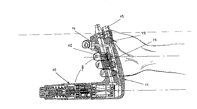
A pneumatic tool, in particular, a screwing tool,
drill, etc., having a barrel portion (10) and a handle (11)
which are inclined relative to each other in such a way that
the respective longitudinal axes form an internal angle of
less than 90°, an actuating button (10) being disposed in the
vicinity of the free end of the handle. The configuration is
advantageous from an ergonomic point of view.


Claims

Note: Claims are shown in the official language in which they were submitted.

-5-
THE EMBODIMENTS OF THE INVENTION IN WHICH AN EXCLUSIVE
PROPERTY OR PRIVILEGE IS CLAIMED ARE DEFINED AS FOLLOWS:
1. A pneumatic tool of gun type comprising: a
barrel portion (10) containing a motor-clutch unit a handle
(11) containing a silencer unit (12), a valve arrangement
(13), a compressed air conduit (14), and an actuating button
(16) for the valve arrangement; the tool being characterized
in that said handle (11) and said barrel portion (10) are
connected in such a way that the respective longitudinal axes
thereof form an internal angle (B) of less than 90° and that
said actuating button (16) is positioned in the proximity of
the end of the handle (11) opposite to that at which it is
connected to the barrel portion (10).

2. A pneumatic tool according to claim
characterized in that, in the most frequent operative
positions, the handle (11) is directed upwardly and inclined
towards the discharge end of the barrel portion (10) in such
a way that the axis of the barrel portion (10) is
substantially parallel to the forearm of the operator and that
the actuating button (16) is in a suitable position for being
actuated by the index finger of the hand of the operator.

Description

Note: Descriptions are shown in the official language in which they were submitted.


20~3931


1 PNE~MATIC T~OL

2 BAC~GRO~ND OF ~E I~v~rg

,
3 The pre~nt invention i~ directed to a pneumatic
4 tool which can be used as a screwin~ tool, a drill, etc. The
pneumatic tool is of an impr~ed construction ~rom an
6 orgonomic point o~ view to permit more con~enient and correct
7 use in di~ferent operating positions.
8 Known pneumatic tool6 are generally of a gun-like
9 configuration in which t~e motor-clutch unit ia disposed in
the barrel portion while disposed in the butt are the valve
11 arrangement for aonnection to the compressed air line, an
12 as~ociated actuating bu~ton, and a silencer unit.
13 ~n th~ ~nown pnoumatic tools, the butt is oriented
14 with respect to the barrel portion in such a way ~hat thQ
respectiv~ a~es form an internal angle of greater than gOo.
16 In addition, the actuating button o~ the valve arrangement is
17 position~d immediately below the barrel portion.
18 The configuration and arran~ement o the components
19 making up the ~nown tools involves disadvantages in terms of
u~- in p~rtlcular operating conditions, for example, when the
21 tool is connected to an overhead compressed air distribution
22 network ~as is no~mal) and is to be used upside down in
23 internal and low position5, including by ambidextrous
24 operators. Consequently, in practice, various pathology
problems have been found to occur (carpal tunnel syndrome,
26 tendinitis problems, wrist inflam~ation, etc.) in regard to
27 the limbs of the operator due to the unsuitable conditions o~
28 use of the tool, with the con~equence of industrlal accidents.


,

2083931
--2--

1 8nMMARy ~F T~E INVENTION

2 The present invention provides a pneumatic tool
3- which is of a particular modified configuration and
4 arrangement in regard to the component parts thereof, in such
a way as to impart thereto an Brgonomic ~tructure which
6 permits mo~e corre~t use thereof in all wor~ing positions,
7 eliminating the above-mentioned injuries ~o the operator.

8 ~ F DESCRIPTION OF ~H~ DRAWINGS

9 For clear and complete understanding of the
invention, the present description, by way of non-limiting
11 example, refers to the accompanying drawings in which:

12 FIG. 1 is an elevational view, in cross-~ection, of
13 a tool in accordance with the prior art, gripped in the normal
14 position;

FIG. 2 iOE an elevational view, in cross-section,
6 showing the prior art tool of FIG. 1 when gripped upside down
17 in the most frequent condition of use; and

18 FIG. 3 is an el-vational view, in cros~-section, of
19 a tool having the features of the present inYention, used in
the correct manner.

21 DSTAIhED DE5CR~TION oF ~RE PREFERRED EM~OPIMENT

22 Referring to FIG. 1, it can be seen that a pneumatic
23 tool in the shape o~ a g~n of a commercially aYailable known
24 type has a barrel portion 10 containing a motor-clutch unit
which does not need to be described in detail in that it doe~
26 not constitute subjeat-matter o~ thi~ invention.

20839~
--3--

1 The tool ~hown in FIG. 1 also has a butt or handle
2 11 whic~ is joined to the barrel port~on 10 in a con~iguration
3 such that the respect~ve longitudinal axes o~ the barrel
4 portion 10 and the handle 11 form an internal angle ~ of
greater than 90~. The handle 11 contains a;silencer unit 12
6 o~ known t~pe and a valve arrangement 13, also of ~nown type.
7 ~he valve arrangement 13 is ~itted into a conduit 14 for the
8 ~low of compre6sed alr. The intake end 15 of the conduit 14
9 i~ connected to a compres6ed air supply network (not shown~,
in particular of overhead type. The handle 11 is al60
11 provided with a push~utton 16 for actuation of the valve
12 arrangement 13.
13 The pushbutton 16 is positioned immediately below
14 the ~unction between the ~arrel portion 10 and the handle 11.
The handle 11 is anatomically shaped in such a way that a
16 hand of the operator can hold khe tool in the position shown
17 in FIG. 1, permitting actuation of the pushbutton 16 by means
18 of the lndex finger of that hand. Such operating condition,
19 however, is not very frequent.
It is very o~ten necessary to work in low positions
21 and in the internal areas of structures. In ~uch cases, the
22 tool must bo used upside down (see FIG. 2), that is to say
23 with the handle oriented upwardly, and necessarily held in
24 such a way that the forearm is incl~n~d with respect to the
axi~ of the barrel portion lo. In addition, actuation of the
26 button 16 has to be effected with the little finger of the
27 hand.
28 In that sit~ation, the di6advantage~ referred to
29 in the opening part o~ the pxesent de~cription are found to
occur. Namely, v~rious pathology problems, such as carpal
31 tunnel syndrome, tendinltis, wrist inflammation and the like
32 occur as a result o the unsuitable adaptation of the prior
33 art tOOl to this u-c~e.
34 With reference now to F~G. 3, described herein i6
a pneumatic tool accerding to the invention, just n~tinq here
36 that the reference n~merals in that figure are exactly the

20~39~1


1 same as those used in FIG. 1, in regard to the ~unctional
2 components of the two tools being the same.
3 FIG. 3 therefore shows: the ~arrel portion 10
4 containing the motor-clutch unit; the handle 11 containing
the silencer unit 12, the valve arrangement 13, and the
6 ~ompres~ed air conduit 14 with the intake end 15; and th~
7 button 16 for actuation of the valve arrangement 13.
8 In comparison with the known tool shown in FIGS. 1
9 and 2, however, it will be observed that the handle 11 is
inclined with respect to the barrel portion 10 at an internal
11 angle B of le8s than 90 and that the button 16 is positione~
12 in the vicinity of the end of the handle opposite to the end
13 at which the handle is connected to the barrel portion.
14 The new configuration of the tool an~ the arrange-
ment of the button 16, in accordance with the present
16 invention, permits the operator, in the most frequent
17 situations of use, to employ the tool upside down but with
18 correct positioning of ~he hand.
19 In fact, as ~hown in FIG. 3, the operator's forearm
is parallel to the axis of the barrel portion 10, and
21 actuation oP the button 16 can be effected by means of the
22 lndex finger of the operator's hand.
23 In these operating condition~, the injurious
24 stresses on the wrist and the forearm of the operator, whioh,
with the previously known tools, give rise to the pathology
26 problems and the accidents re~erred to above, are eliminated.
27 Althou~h the preferred em~odiments of this invention
28 have been shown and described, it should be understood that
29 various modifications and rearrangements of the parts may be
resorted to without departing rrom the scope of the invention
31 as disclosed and claimed herein.

Representative Drawing
A single figure which represents the drawing illustrating the invention.
Administrative Status

For a clearer understanding of the status of the application/patent presented on this page, the site Disclaimer , as well as the definitions for Patent , Administrative Status , Maintenance Fee  and Payment History  should be consulted.

Administrative Status

Title Date
Forecasted Issue Date Unavailable
(22) Filed 1992-11-26
(41) Open to Public Inspection 1993-05-29
Dead Application 1997-11-26

Abandonment History

Abandonment Date Reason Reinstatement Date
1996-11-26 FAILURE TO PAY APPLICATION MAINTENANCE FEE

Payment History

Fee Type Anniversary Year Due Date Amount Paid Paid Date
Application Fee $0.00 1992-11-26
Registration of a document - section 124 $0.00 1993-06-04
Maintenance Fee - Application - New Act 2 1994-11-28 $100.00 1994-07-28
Maintenance Fee - Application - New Act 3 1995-11-27 $100.00 1995-11-24
Registration of a document - section 124 $0.00 1996-06-13
Owners on Record

Note: Records showing the ownership history in alphabetical order.

Current Owners on Record
ELECTROLUX ZANUSSI ELETTRODOMESTICI S.P.A.
Past Owners on Record
GRILLI, GABRIELE
SPEDALUZZI, GUERRINO
ZANUSSI ELETTRODOMESTICI S.P.A.
Past Owners that do not appear in the "Owners on Record" listing will appear in other documentation within the application.
Documents

To view selected files, please enter reCAPTCHA code :


To view images, click a link in the Document Description column. To download the documents, select one or more checkboxes in the first column and then click the "Download Selected in PDF format (Zip Archive)" or the "Download Selected as Single PDF" button.

List of published and non-published patent-specific documents on the CPD .

If you have any difficulty accessing content, you can call the Client Service Centre at 1-866-997-1936 or send them an e-mail at CIPO Client Service Centre.


Document
Description 
Date
(yyyy-mm-dd) 
Number of pages   Size of Image (KB) 
Representative Drawing 1998-09-10 1 31
Drawings 1993-05-29 3 92
Claims 1993-05-29 1 29
Abstract 1993-05-29 1 12
Cover Page 1993-05-29 1 13
Description 1993-05-29 4 161
Office Letter 1996-06-26 1 15
Fees 1995-11-24 1 78
Fees 1994-07-28 1 85