Language selection

Search

Patent 2083987 Summary

Third-party information liability

Some of the information on this Web page has been provided by external sources. The Government of Canada is not responsible for the accuracy, reliability or currency of the information supplied by external sources. Users wishing to rely upon this information should consult directly with the source of the information. Content provided by external sources is not subject to official languages, privacy and accessibility requirements.

Claims and Abstract availability

Any discrepancies in the text and image of the Claims and Abstract are due to differing posting times. Text of the Claims and Abstract are posted:

  • At the time the application is open to public inspection;
  • At the time of issue of the patent (grant).
(12) Patent Application: (11) CA 2083987
(54) English Title: BAT FOR CATCHING GAMES
(54) French Title: BATON DE JEU
Status: Deemed Abandoned and Beyond the Period of Reinstatement - Pending Response to Notice of Disregarded Communication
Bibliographic Data
(51) International Patent Classification (IPC):
  • A63B 59/20 (2015.01)
(72) Inventors :
  • TALBOT, MARIE LOUIS CLAUDE (Mauritius)
(73) Owners :
  • MARIE LOUIS CLAUDE TALBOT
(71) Applicants :
(74) Agent: BARRIGAR & MOSS
(74) Associate agent:
(45) Issued:
(22) Filed Date: 1992-11-27
(41) Open to Public Inspection: 1993-06-21
Availability of licence: N/A
Dedicated to the Public: N/A
(25) Language of filing: English

Patent Cooperation Treaty (PCT): No

(30) Application Priority Data:
Application No. Country/Territory Date
91/10031 (South Africa) 1991-12-20

Abstracts

English Abstract


APPLICANT: MARIE LOUIS CLAUDE TALBOT
TITLE: BAT FOR CATCHING GAMES
ABSTRACT
A bat or racquet for a new ball catching game has a handle and a
head, the head having an orifice through which the ball can pass
and having a net-like material against which the caught ball
strikes. The net like material is attached to a pair of opposed
elements which are slidable in a frame inside the bat. The
opposed elements are spring loaded with the springs being arranged
to be off-centre for the elements to snap between a first ball-
receiving condition, and a second ball capturing condition.


Claims

Note: Claims are shown in the official language in which they were submitted.

CLAIMS:
1.
A bat, racquet or the like includes a handle and a head, the head
including an orifice through which a ball may pass, the orifice
including flexible ball catching material, the catching material
being included between a pair of elements slidable in a frame between
a first position in which the ball passes therebetween and a second
position to which the elements are moved by virtue of the catching
material being acted upon by the entering ball, the elements being
adapted to retain the ball in the second position.
2.
The bat, racquet according to claim 1 in which the elements are
spring loaded to bias them in each of the two positions.
3.
The bat, racquet according to either of the above claims in which the
springs act bi-directionally, corresponding to the position of the
elements the change of direction occuring intermediate the first and
second positions.
-6-

4.
The bat, racquet according to claim 3 in which the springs have two
off-centre positions for reversible spring action.
5.
The bat, racquet according to claim 3 in which the spring action is
directed to a position which is off centre having regard to the end
attachments or bearings of the springs.
6.
The bat, racquet according to any of the above claims in which the
elements are curved at their insides.
7.
The bat, racquet according to any of the above claims in which the
combined action caused by the entrance of the ball against the
catching material and the spring action, causes the elements to snap
from the first to the second position and the ball is held captive
until forced outwardly by thumb action, when the elements are forced
apart against the spring action and they snap back to the first
position.
-7-

8.
The bat, racquet according to any of the above claims in which the
frame and elements are contained between opposed bat formations and
the assembly screwed together.
9.
A bat, racquet or the like substantially as described with reference
to the accompanying drawings.
-8-

Description

Note: Descriptions are shown in the official language in which they were submitted.


~ '~ 7
FIELD OF THE INVENTION
This invention rela-tes to a bat for a catching game.
BACKGROUND OF THE INVENTION
There are many games which involve the catching of a ball with a bat,
racquet or like and the ball is then thrown from the bat. Such games
include pelo-ta and lacrosse.
Beach tennis bats are also known, but it is an object of the present
invention to provide a new game which can be played anywhere and
which gives young and old excellent enjoyment and exercise.
THE INVENTION
.
According to the invention a bat, racquet or the like includes a
handle and a head, the head including an orifice through which a ball
may pass, the orifice including flexible ball catching material, the
catching material being included between a pair of elements slidable
in a frame between a first position in which the ball passes
therebetween and a second position to which the elements are moved by
virtue of the catching material being acted upon by the entering
ball, the elements being adapted to retain the ball in the second
position.
In a preferred form of the invention the elements are spring loaded

to bias -them in each of the two positions.
In one form of the invention leaf springs are provided which act
bi-directionally corresponding to the position of the elements, the
change of direction occuring intermediate the first and second
positions. For example, the springs may have two off-centre
positions so that the spring action is reversable. Alternatively,
the spring action may be directed to a position which is off centre
having regard to the end attachments or bearings of the springs.
The elements are preferably curved at their insides - i.e. the sides
which receive the ball.
The combined action caused by the entrance of the ball against the
catching material and the spring action, causes the elements to snap
from the first to the second position and the ball is held captive
until forced outwardly by thumb action, when the elements are forced
apart against the spring ac-tion and they snap back to the first
position.
The frame and elements may be contained between opposed bat
formations and the assembly screwed together.
EMBODIMENT OF THE INVENTION
An embodiment of the invention is described below with reference to
the accompanying drawings in which:

.~ '37
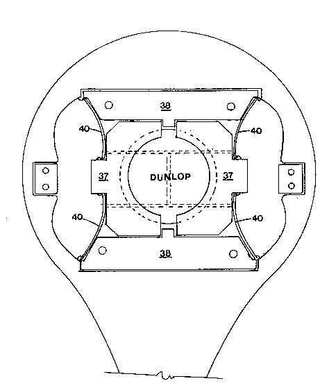
Figure A is a front view of a bat according -to the invention;
Figure B and C are similar views with one of the bat formations
removed -to illustrate the internal mechanism of -the catching
arrangement.
In the drawings a bat 10 has a handle 32 and head 33, the latter
having an orifice 34 which is large enough comfortably to receive a
ball.
The orifice is obturated by means of a pair of lines 35 with a cross
line 36.
Referring to Figure B and C, the lines 35 are attached to opposing
elements 37 which are slidable in frames 38.
The elements 37 have curved interior sides 39 and these are spaced
even further apart than the diameter of the orifice 34. In a first
position as shown in Figure B, the leaf springs 40 act between points
41 and 42 and due to the curvature thereof, the elements 37 are
maintained in the open position of Figure B and the lines 35 are
maintained in a taut condition.
A flying ball, on entering the orifice 34, will strike the lines 35
with a force sufficient to cause the elements 37 to move rapidly
towards each other, duly assisted by the reverse spring action which
will be imparted and the ball will be caught by means of the
resulting snap action, and a situation as shown in Figure C will

~r ~ C.~
obtaln.
When it is required to free the ball, it is merely pushed in the
opposite direction, by which action the elements are pushed away from
each other sufficiently for the spring action to reverse itself once
more so that it snaps again to the first position as shown in Figure
B.
The springs 40 may have notches out into -their ends and these engagewith complemental formations at points 41 and 42.

Representative Drawing
A single figure which represents the drawing illustrating the invention.
Administrative Status

2024-08-01:As part of the Next Generation Patents (NGP) transition, the Canadian Patents Database (CPD) now contains a more detailed Event History, which replicates the Event Log of our new back-office solution.

Please note that "Inactive:" events refers to events no longer in use in our new back-office solution.

For a clearer understanding of the status of the application/patent presented on this page, the site Disclaimer , as well as the definitions for Patent , Event History , Maintenance Fee  and Payment History  should be consulted.

Event History

Description Date
Inactive: IPC deactivated 2017-09-16
Inactive: IPC assigned 2016-07-14
Inactive: First IPC assigned 2016-07-14
Inactive: IPC expired 2015-01-01
Application Not Reinstated by Deadline 1998-11-27
Time Limit for Reversal Expired 1998-11-27
Deemed Abandoned - Failure to Respond to Maintenance Fee Notice 1997-11-27
Application Published (Open to Public Inspection) 1993-06-21

Abandonment History

Abandonment Date Reason Reinstatement Date
1997-11-27
Owners on Record

Note: Records showing the ownership history in alphabetical order.

Current Owners on Record
MARIE LOUIS CLAUDE TALBOT
Past Owners on Record
None
Past Owners that do not appear in the "Owners on Record" listing will appear in other documentation within the application.
Documents

To view selected files, please enter reCAPTCHA code :


To view images, click a link in the Document Description column. To download the documents, select one or more checkboxes in the first column and then click the "Download Selected in PDF format (Zip Archive)" or the "Download Selected as Single PDF" button.

List of published and non-published patent-specific documents on the CPD .

If you have any difficulty accessing content, you can call the Client Service Centre at 1-866-997-1936 or send them an e-mail at CIPO Client Service Centre.


Document
Description 
Date
(yyyy-mm-dd) 
Number of pages   Size of Image (KB) 
Abstract 1993-06-20 1 12
Claims 1993-06-20 3 39
Drawings 1993-06-20 3 37
Descriptions 1993-06-20 4 75
Representative drawing 1998-10-18 1 13
Courtesy - Abandonment Letter (Maintenance Fee) 1997-12-28 1 185
Fees 1996-11-17 1 42
Fees 1995-11-21 1 38
Fees 1994-11-17 1 37
PCT Correspondence 1993-03-04 1 36
PCT Correspondence 1993-09-08 1 24
Courtesy - Office Letter 1993-05-16 1 20