Language selection

Search

Patent 2083989 Summary

Third-party information liability

Some of the information on this Web page has been provided by external sources. The Government of Canada is not responsible for the accuracy, reliability or currency of the information supplied by external sources. Users wishing to rely upon this information should consult directly with the source of the information. Content provided by external sources is not subject to official languages, privacy and accessibility requirements.

Claims and Abstract availability

Any discrepancies in the text and image of the Claims and Abstract are due to differing posting times. Text of the Claims and Abstract are posted:

  • At the time the application is open to public inspection;
  • At the time of issue of the patent (grant).
(12) Patent: (11) CA 2083989
(54) English Title: GRAB HOOK FOR ATTACHMENT TO A CHAIN TO PROVIDE PARTIAL LINK ADJUSTMENT
(54) French Title: CROCHET PRENEUR POUR CHAINE ET PERMETTANT DE REGLER PARTIELLEMENT LE MAILLON
Status: Term Expired - Post Grant Beyond Limit
Bibliographic Data
(51) International Patent Classification (IPC):
  • F16G 17/00 (2006.01)
(72) Inventors :
  • MACKENZIE, DOUGLAS JOHN (Canada)
(73) Owners :
  • DOUGLAS JOHN MACKENZIE
(71) Applicants :
  • DOUGLAS JOHN MACKENZIE (Canada)
(74) Agent: LAMBERT INTELLECTUAL PROPERTY LAW
(74) Associate agent:
(45) Issued: 2003-05-06
(22) Filed Date: 1992-11-27
(41) Open to Public Inspection: 1994-05-28
Examination requested: 1999-10-26
Availability of licence: N/A
Dedicated to the Public: N/A
(25) Language of filing: English

Patent Cooperation Treaty (PCT): No

(30) Application Priority Data: None

Abstracts

English Abstract


A hook for gripping chain is asymmetrical so
that the effective chain length can be adjusted to a part
link tightness. The attachment end of the hook is offset
from the plane of the hook end, which includes the slot
for receiving a link of a chain. If the chain enters from
one side of the hook, the chain and hook nave a different
angle than when the chain enters from the other side of
the hook. The resulting change in angle and hence the way
the hook interferes with the chain changes the length of
chain required for the chain to reach the slot.


Claims

Note: Claims are shown in the official language in which they were submitted.

8
THE EMBODIMENTS OF THE INVENTION IN WHICH AN EXCLUSIVE
PROPERTY OR PRIVILEGE IS CLAIMED ARE DEFINED AS FOLLOWS:
1. In combination, a first chain having a gripping
link, and a hook for attachment to the first chain and
for attachment to a second chain or like member, the hook
comprising:
a body having a first end and a second end;
the second end having attachment means for
attaching the hook to the second chain or like member;
the first end including a slot for receiving a
link of the first chain adjacent the gripping link, the
slot defining a plane; and
the attachment means lying outside the plane of
the slot, whereby depending upon the side of the hook the
gripping link abuts against, the distance from the
attachment means to a given point on the first chain may
be a first distance or a second distance.
2. The combination of hook and chain in claim 1 in
which the length of a link of the first chain is defined
by its pitch and the difference between the first
distance and the second distance is about half of the
pitch of a link.
3. A method of attaching a hook to a first chain
having a gripping link, the link having a longitudinal
axis, in which the hook includes a body having a first
end and a second end; the second end having attachment
means for attaching the hook to a second chain or like
member; the first end including a slot for receiving a
link of the first chain adjacent the gripping link, the

9
slot defining a plane and having a first side and a
second side; and the attachment means lying outside the
plane of the slot; the link being initially within the
slot with the gripping link on the first side of the
slot; the method comprising the steps of:
removing the link from the slot, rotating the
link 180° about an axis perpendicular to the longitudinal
axis of the link and inserting the link back into the
slot with the gripping link on the second side of the
slot, thereby changing the distance from the attachment
means to a given point on the first chain from a first
distance to a second distance.

Description

Note: Descriptions are shown in the official language in which they were submitted.


r~'~~ s~~~
2
FIELD OF THE INVENTION
This invention relates to hooks for attaching
to chains, particularly for but not limited to use with
load binders.
BACKGROUND AND SUMMAR91 OF THE INVENTION
A load binder is a device that is used to
tighten a chain or cable to secure a load on a vehicle.
A lever type load binder 11 is illustrated in Figure 1.
Movement of the lever 13 in the direction of the arrow
shortens the distance between the two grab hooks 15 and
17. The lever 13 snaps over center at the end of its
stroke and the chain tension holds the load binder
closed. The grab hooks 15 and 17 are designed to grab
chain links of a chain (not shown).
When load binders are tightened the degree of
tension is in part determined by the distance between the
links in the chain. Typical hooks used on load binders
have a longitudinal slot through which one chain link
passes with little clearance. Since adjacent chain links
are at right angles, more or less, to each other, the
next chain link cannot pass through the slot and the
chain is held by the hook. The load binder may grasp the
chain at any link and may be tightened. Typical chains
are made of links that are all the same size, and so the
tightness can be adjusted to the chain link that is
closest to the tightest point the load binder can be
tightened to. However, this may result in nearly a full
chain link of looseness, if the binder cannot quite be
tightened to the next link.
The inventor has proposed a solution to this
problem in which the chain may be 'tightened in partial

~~~ S~V
3
link increments instead of full link increments. The
invention uses the principle that the length of the chain
that is used up depends on the angle of the slot in the
hook and interference between the chain and the body of
the hook. The slot may be taken to lie in a plane. Over
small angles, the closer a perpendicular to this plane is
to being parallel to the direction of tightening, the
less the amount of chain required to reach into the slot.
Hence the invention provides a hook that is asymmetrical
(the attachment end is offset from the hook end) so that
when the chain enters the hook from one side it requires
less length of chain than when it enters the other side.
By appropriate choice of the amount of offset or
asymmetry, the change in length required can be set to
part of a chain link, preferably half a link.
While the invention has been described for use
with a chain and load binder, it should be observed that
the hook has utility to link anything that may be
attached to the hook on one end with a chain on the other
end.
BRIEF DESCRIPTION OF THE DRAWINGS
There will now be described a preferred
embodiment of the invention; with reference to the
drawings, by way of illustration, in which like numerals
denote like elements and in which:
Figure 1 is a side view of a prior art load
binder;
Figure 2 is a perspective view of a hook
according to the invention;
Figure 3 is a side view of the hook of Figure
2;

,q~ in ~
4
Figure 4 is an end view of the hook of Figure
2;
Figure 5 is a perspective view of a further
embodiment of a hook according to the invention;
Figure 6 is a perspective view of a further
embodiment of a hook according to the invention;
Figure 7 is a perspective view of a further
embodiment of a hook according to the invention;
Figure 8 is a perspective view of a further
embodiment of a hook according to the invention;
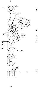
Figure 9 is a side view of a hook according to
the invention attached to a chain in one way showing a
longer length of the distance L between a specific link
in the chain and the attachment point of the hook; and
Figure 10 is a side view of the hook of Figure
9 attached to a chain in another way showing a shorter
length of the distance L.
DETAILED DESCRIPTION OFPREFERRED EMBODIMENTS
Referring to Figs. 2, 3 and 4 there is shown a
grab hook l0 according to the invention. The hook 10 has
an attachment end l2 and a hook end 14. The attachment
end 12 is of the clevis type, which is readily attachable
or detachable to another chain or like member by
inserting or removing pin l8 from the eyes 19. The hook
end 14 defines a plane A which is in -the plane of the
sheet of the drawing in Figure 3 and perpendicular to the
sheet as shown in Figure 4. The hook end 14 includes a
slot l6 that is in the plane of the hook. The plane of
the hook end T4 may be considered to be defined by the
slot 16. The longitudinal axis of the slot lies in the
plane A (see Figure 4) and the lateral dimension of the

a'1 f~ '~
~N ~ L919 l' ~
slot also lies in the plane A (see Figure 3). As clearly
shown in Figure 4, the attachment end 12 is offset from
the plane A of the hook.
A further embodiment of the invention is shown
5 in Figure 5. The hook 50 includes a hook end 54 and an
attachment end 52. The hook end 54 defines a plane in
which lies a slot 56. The attachment end 52 lies outside
of the plane of the hook. The shank 57 of the hook is
formed in this case with a single curve. Other
configurations of the shank may be used to obtain the
desired offset. However, the double curve shown in
Figures 2, 3 and 4 is preferred. Use of a single curve
over the double curve is not preferred because high
bending stresses require the shank to be thicker near the
curve, which complicates the manufacture of the hook.
Figure 6 shows a further hook 60 having an
eyelet type attachment end 62 and a hook end 64 in which
lies a slat 66 defining a plane. The attachment end 62
lies outside of the plane of the hook end 64. Figure 7
shows a similar hook 70 to that of Figure 6 with
attachment end 72 and hook end 74, but the hook shows a
different configuration of the shank. Figure 8 also shows
a hook 80 having an eyelet type attachment end 82 and a
hook end 84 in which lies a slot 86 defining a plane. The
eyelet is more or less perpendicular to the plane of the
hook end. The attachment end lies out of the plane of the
hook end.
Figures 9 and 10 show a hook 50 of the type
shown in Figures 2, 3 and 4 attached to a link 91 of a
chain 93. The load is being tightened along the line B-B
which passes through the main portion of the chain 93 and
the attachment end 52 of the hook. Since the plane of the

s
hook end 54 is offset, it cannot lie along the line B-B
(otherwise the attachment end 52 would be in the plane of
the hook end 54). Figures 9 and 10 show two possible
positions for the hook 50 to lie in. The angle of the
chain link 91 differs in the two positions and this
changes the length of chain required to reach the slot
56. Thus, given a link in the chain 93 (link 95 for
example), the distance L between it and the attachment
end 52 may be changed by a part of the pitch of a link by
moving the chain 93 from entering one Side of the slot as
shown in Figure 9 to entering the other side shown in
Figure 10. In the example shown, the part of the pitch of
a link is about one half of the pitch. Interference at
the lower end 90 of the hook 50 in Figure 10 also tends
to shorten the chain (that is, lengthens the path that
the chain takes).
The Link 97 adjacent to the link 91 on the
short end of the chain is the gripping link, and
depending on which side the chain passes through, the
link~97 will abut against one side of the hook end or the
other. Ths length of the chain may also be changed
slightly by making the hook end asymmetrical about the
plane A, for example by thickening one side of the hook
and thinning the other. While this manner of changing the
chain length is not preferred, it may be used to enhance
the operation of the invention. The pitch, shown as p in
Figure 9, of a link is the total length of the chain
divided by the total number of links in that length of
the chain.
Alternative Embodiments
A person skilled in the art could make
immaterial modifications to the invention described and

r ~ tyn~,
... i.L' ~1~ 4
claimed in this patent without departing from the essence
of the invention.

Representative Drawing
A single figure which represents the drawing illustrating the invention.
Administrative Status

2024-08-01:As part of the Next Generation Patents (NGP) transition, the Canadian Patents Database (CPD) now contains a more detailed Event History, which replicates the Event Log of our new back-office solution.

Please note that "Inactive:" events refers to events no longer in use in our new back-office solution.

For a clearer understanding of the status of the application/patent presented on this page, the site Disclaimer , as well as the definitions for Patent , Event History , Maintenance Fee  and Payment History  should be consulted.

Event History

Description Date
Revocation of Agent Requirements Determined Compliant 2020-04-22
Appointment of Agent Requirements Determined Compliant 2020-04-22
Inactive: Expired (new Act pat) 2012-11-27
Inactive: Late MF processed 2011-02-14
Inactive: Adhoc Request Documented 2011-01-28
Letter Sent 2010-11-29
Grant by Issuance 2003-05-06
Inactive: Cover page published 2003-05-05
Pre-grant 2003-02-20
Inactive: Final fee received 2003-02-20
Notice of Allowance is Issued 2002-12-10
Letter Sent 2002-12-10
Inactive: Approved for allowance (AFA) 2002-11-21
Amendment Received - Voluntary Amendment 2002-10-17
Inactive: S.30(2) Rules - Examiner requisition 2002-09-23
Amendment Received - Voluntary Amendment 2000-02-24
Inactive: Application prosecuted on TS as of Log entry date 1999-11-26
Letter Sent 1999-11-26
Inactive: Status info is complete as of Log entry date 1999-11-26
Request for Examination Requirements Determined Compliant 1999-10-26
All Requirements for Examination Determined Compliant 1999-10-26
Application Published (Open to Public Inspection) 1994-05-28
Small Entity Declaration Determined Compliant 1992-11-27

Abandonment History

There is no abandonment history.

Maintenance Fee

The last payment was received on 2002-11-15

Note : If the full payment has not been received on or before the date indicated, a further fee may be required which may be one of the following

  • the reinstatement fee;
  • the late payment fee; or
  • additional fee to reverse deemed expiry.

Please refer to the CIPO Patent Fees web page to see all current fee amounts.

Fee History

Fee Type Anniversary Year Due Date Paid Date
MF (application, 5th anniv.) - small 05 1997-11-27 1997-11-06
MF (application, 6th anniv.) - small 06 1998-11-27 1998-10-29
MF (application, 7th anniv.) - small 07 1999-11-29 1999-10-25
Request for examination - small 1999-10-26
MF (application, 8th anniv.) - small 08 2000-11-27 2000-10-26
MF (application, 9th anniv.) - small 09 2001-11-27 2001-11-01
MF (application, 10th anniv.) - small 10 2002-11-27 2002-11-15
Final fee - small 2003-02-20
MF (patent, 11th anniv.) - small 2003-11-27 2003-10-27
MF (patent, 12th anniv.) - small 2004-11-29 2004-09-28
MF (patent, 13th anniv.) - small 2005-11-28 2005-11-23
MF (patent, 14th anniv.) - small 2006-11-27 2006-10-18
MF (patent, 15th anniv.) - small 2007-11-27 2007-11-21
MF (patent, 16th anniv.) - small 2008-11-27 2008-11-21
MF (patent, 17th anniv.) - small 2009-11-27 2009-11-19
MF (patent, 18th anniv.) - small 2010-11-29 2011-02-14
Reversal of deemed expiry 2010-11-29 2011-02-14
MF (patent, 19th anniv.) - small 2011-11-28 2011-10-05
Owners on Record

Note: Records showing the ownership history in alphabetical order.

Current Owners on Record
DOUGLAS JOHN MACKENZIE
Past Owners on Record
None
Past Owners that do not appear in the "Owners on Record" listing will appear in other documentation within the application.
Documents

To view selected files, please enter reCAPTCHA code :


To view images, click a link in the Document Description column. To download the documents, select one or more checkboxes in the first column and then click the "Download Selected in PDF format (Zip Archive)" or the "Download Selected as Single PDF" button.

List of published and non-published patent-specific documents on the CPD .

If you have any difficulty accessing content, you can call the Client Service Centre at 1-866-997-1936 or send them an e-mail at CIPO Client Service Centre.


Document
Description 
Date
(yyyy-mm-dd) 
Number of pages   Size of Image (KB) 
Representative drawing 2002-12-11 1 5
Cover Page 2003-04-02 2 34
Cover Page 1995-04-08 1 71
Claims 1995-04-08 3 182
Drawings 1994-04-08 4 49
Description 1994-04-08 6 184
Abstract 1994-04-08 1 20
Claims 2000-02-24 2 58
Representative drawing 1999-06-28 1 3
Reminder - Request for Examination 1999-07-28 1 127
Acknowledgement of Request for Examination 1999-11-26 1 179
Commissioner's Notice - Application Found Allowable 2002-12-10 1 160
Maintenance Fee Notice 2011-01-10 1 171
Late Payment Acknowledgement 2011-02-23 1 164
Fees 2002-11-15 1 28
Correspondence 2003-02-20 1 29
Fees 2003-10-27 1 26
Fees 1998-10-29 1 31
Fees 1997-11-06 1 37
Fees 2004-09-28 1 29
Fees 2005-11-23 1 28
Fees 2006-10-18 1 41
Fees 2007-11-21 1 88
Fees 2008-11-21 1 50
Fees 2009-11-19 1 46
Fees 2011-02-14 1 53
Fees 2011-10-05 1 43
Fees 1995-07-25 1 42
Fees 1996-10-23 1 52
Fees 1994-09-06 1 42