Note: Descriptions are shown in the official language in which they were submitted.
F-6328
-~.- f a ~~ ~. ~. a
A SINGLE HORIZO3dTAL WELL CONDUCTION ASSISTED
STEAP~ DRIVE PROCESS FOR REI~IOVI3~IG
VISCOUS IiYDROCARBONACEOUS FLUIDS
This invention is directed to the removal of
viscous hydrocarbonaceous fluids from a reservoir or
formation. These fluids are removed from the reservoir
by using a horizontal well in combination with
conduction assisted steam flooding in a reservoir
having limited native injectivity and a high
water-saturated bottom zone.
In many areas of the world, there are large
deposits of viscous petroleum. Examples of viscous
petroleum deposits include the Athabasca and Peace
River regions in Canada, the Jobo region in Venezuela
and the Edna and Sisquoc regions in California. These
deposits are generally called tar sand deposits due to
the high viscosity of the hydrocarbon which they
contain. These tar sands may extend for many miles and
may occur in varying thickness of up to more than 300
feet. Although tar sands may lie at or near the
earth's surface, generally they are located under an
overburden which ranges in thickness from a few feet to
several thousand feet. Tar sands located at these
depths constitute one of the world°s largest presently
known petroleum deposits.
Tar sands contain a viscous hydrocarbon material,
which is commonly referred to as bitumen, in an amount
which ranges from about 5 to about 16 percent by
weight. This bitumen is usually immobile at typical
reservoir temperatures. For example, at reservoir
temperatures of about 60°F, bitumen is immobile, having
a viscosity frequently exceeding several thousand
poises, At higher temperatures, such as temperatures
exceeding 200°F, the bitumen becomes mobile with a
viscosity of less than 345 centipoises.
F'-6328
c> 47
~v~c;!~~.~ F
-2-
In situ heating is among the most promising
methods for recovering bitumen from tar sands because
there is no need to move the deposit and thermal energy
can substantially reduce the bitumen's viscosity.
Thermal energy may be introduced to tar sands in a
variety of forms. for example, hot water, in situ
combustion, and steam have been suggested to heat tar
sands. Although each of these thermal energy agents
may be used under certain conditions, steam is
generally the most economical and efficient. It is
clearly the most widely employed thermal energy agent.
Thermal stimulation processes appear promising as
one approach for introducing these thermal agents into
a formation to facilitate flow and production of
bitumen therefrom. In a typical steam stimulation
process, steam is injected into a viscous hydrocarbon
deposit by means of a well for a period of time after
which the steam-saturated formation is allowed to soak
for an additional interval prior to placing the well on
production.
To accelerate the input of heat into the
formations, it has been proposed to drill horizontally
deviated wells or to drill lateral holes outwardly from
a main borehole or tunnel. Examples of various thermal
systems using horizontal wells are described in U.S.
Pat. No. 1,634,236; U.S. Pat. No. 1,816,260; 2,365,591:
3,024,013; 3,338,306; 3,960,213; 3,986,557; and
Canadian Pat. No. 481,151. However, processes which
use horizontal wells to recover bitumen from tar sand
deposits are subject to several drawbacks.
One problem encountered with use of horizontal
wells to recover bitumen is the difficulty of passing a
heated fluid through the horizontal well. During well
completion bitumen will sometimes drain into the well
completion assembly. This bitumen may block fluid flow
F-6328
through substantial portions of the horizontal well and
thereby decrease heating efficiency.
Another problem which is encountered when using
horizontal wells is that often the area stimulated is
insufficient to make it economical to recover
hydrocarbonaceous fluids from the reservoir or
formation. Additionally, when horizontal wells are
utilized in a water saturated bottom water zone, water
coning often causes too much water to be produced with
the hydrocarbonaceous fluids. Water coning is the
phenomenum where water is drawn upwardly from a
water-bearing portion of a formation into the
oil-bearing portion about the well. Water coning
causes free water to be produced in the well which
results in a much higher water-to-oil ratio than would
be the case without water coning. This higher
water-to-oil ratio is undesirable and results in
increased operating costs.
Therefore, what is needed is a method to thermally
stimulate viscous hydrocarbonaceous fluids in a
formation or reservoir which has limited native
injectivity where a high water-saturated bottom zone is
encountered.
This invention is directed to a horizontal well
steam flooding oil recovery process for viscous
hydrocarbonaceous fluid containing reservoirs having
limited native injectivity and a water-saturated bottom
water zone comprising:
a) directing a cased horizontal well into said
reservoir above the bottom water zone for a
distance determined to be the most effective and
efficient for the recovery of hydrocarbo-naceous
fluids from the reservoir;
b) perforating said well on its top side at two
spaced apart intervals within the determined
distance so as to make a first and second
F--6328
perforated interval for fluid communisation with
the well;
c) inserting raithin said well to its farthest end
an uninsulated tubing having a circumference
smaller than the well where the tubing provides
for a first conduit and also causes a second
conduit to be formed in annular space between said
tubing and casing within the well thereby allowing
for steam communication and removal of fluids from
said reservoir;
d) injecting steam into the second conduit at a
pressure higher than the reservoir pressure and
flowing steam from the well via the first conduit
for a time sufficient to mobilize said viscous
fluids near said wellbore;
e) reducing steam injection pressure arid producing
hydrocarbonaceous fluids of reduced viscosity,
steam, and water to the surface by the first
conduit:
f) repeating steps d) and e) until thermal
communication is established between perforations
in the two spaced apart intervals:
g) removing the tubing from said well and fitting
the tubing with a thermal packer so as to allow
the tubing and packer to be placed into the
horizontal well:
h) inserting the tubing and packer into said well
so as to position the packer in a manner sufficent
to form two isolated, spaced apart, perforated
intervals thereby causing one spaced apart
interval with perforations therein to serve as an
injector conduit while the other perforated
interval serves as a producer conduit: and
i) injecting steam into the reservoir via the
injector conduit while removing hydrocarbonaceous
fluids, steam, and water by the producer conduit.
CA 02084113 2002-05-O1
-5-
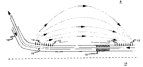
The drawing is a schematic representation of the
horizontal wellbore containing two perforated
spaced-apart intervals and positioned over a water
bottom zone in a reservoir.
In the practice of this invention, referring to
the drawing, horizontal well 10 is directed through
limited native injectivity reservoir 8. The well is
subsequently cased. Well 10 proceeds horizontally
through formation 8 for a distance of about 600 feet.
It is placed about 5 feet above high water-saturated
zone or bottom water zone 14. Horizontal well 10 is
about 7" in diameter and is cemented in a manner so as
to be suitable for thermal operation at temperatures
between about 450° to about 560°F operating
temperatures. Thereafter, horizontal well 10 is
perforated at two separate spaced-apart locations.
Each of the spaced-apart locations are at least 150
feet long and are perforated with 4 shots per foot so
as to form perforations 12. In this manner two
separate spaced apart perforated intervals are made in
wellbore 10 so as to be in fluid communication with
formation 8.
Perforations which are at the top of cased
horizontal wellbore 10 can be made by any type of
perforating gun. It is preferred to use those
perforating guns such as a jet gun that can provide the
roundest and most burr-free perforations. Any number
of mechanical or magnetic-type decentralized
perforating guns can be utilized for perforating along
the top of the horizontal casing. A magnetic-type
perforating gun uses magnets to orient the gun at the
top of the casing. One type of casing gun is disclosed
in U.S. Patent No. 4,153,118. However, as will be
obvious to one skilled in the art, other types of
perforating guns can be used as long as they are
suitably capable
F-6328
~~r ~~~
of being oriented as required. The distance between
the two perforated sections is at least about 300 feet.
Another reason for perforating the well on its top side
is to minimize water influx from bottom water zone 14,
and to also take advantage of steam override.
After perforating the casing to the extent above-
mentioned, a 2-7/8" uninsulated liner or tubing 16 is
run through well 10 to its far and. Since the
circumference of the liner is smaller than the diameter
of the wellbore, the tubing thus provides a first
conduit and also causes a second conduit to be formed
in an annular space existing between the outside of
said tubing and the well casing. Thus, two separate
conduits exist for injecting steam into a formation and
also for removing steam from the formation as well as
any produced hydrocarbonaceous fluids.
Having positioned uninsulated liner or tubing 16
in the manner desired in the horizontal wellbore 10,
steam injection is commenced into the annular space
formed between the outside of the tubing 16 and well
casing 10, hereinafter identified as the second
conduit, Steam injection is continued at the rate of
100 barrels per day cold water equivalent (CWE) into
the second conduit and it flows back through wellbore
10 via the first conduit formed in liner or tubing 16.
Steam injection is conducted at a pressure slightly
higher than the reservoir pressure for about 15 days.
Steam injection pressure can be controlled at the
surface by adjusting chokes positioned in the first
conduit. After 15 days, steam injection pressure is
reduced. Reduction in steam injection pressure is
obtained by reducing the steam injection rate to about
50 barrels per day CWE. Steam which has been
circulated through wellbore 10 and injected into
formation 8 via perforations 12 contained in wellbore
10 heats up a radial volume around said wellbore so as
F-63z$
_7_
to cause hydrocarbonaceous fluids in that volume to
become reduced in viscosity. Hydrocarbonaceous fluids
of reduced viscosity are produced to the surface along
with any water or steam until no hydrocarbonaceous
fluids are observed in the production stream.
Production to the surface in this manner is continued
for about ten days. In order to establish thermal and
fluid communication between perforations contained on
the near and far ends of wellbore 10, the steam
injection and fluid production steps are repeated.
At the end of the steam injection and production
phase, tubing 16 is pulled from wellbore 10. A thermal
packer 18 is positioned on tubing 16. Subsequently,
tubing 16 containing thermal packer 18 is reinserted
into wellbore 10 in a manner so as to position packer
18 adjacent to the area containing perforations at the
furtherest point of well l0. Thus, the packer is
positioned so as to form two separated, spaced-apart,
perforated intervals within well 10. Fluid
communication between the two intervals in wellbore 10
is precluded since the annular space between liner 16
and the well casing is blocked. While one spaced-apart
interval serves as an injector conduit, the other
perforated interval serves as a producer conduit for
fluid communication with reservoir 8.
Having separated wellbore 10 into two separate
conduits for fluid communication with formation 8,
steam injection is commenced. Steam is directed down
the annular space formed with the outside of tubing 16
and the well casing. Perforations contained in the
well casing closest tc~ its vertical portion (near-end)
allow steam to enter formation 8 where it contacts
hydrocarbonaceous fluids. Steam pressure is such that
it allows the steam to flow into formation 8 and
eventually contact perforations contained in the
furtherest end of wellbore 10. When contact is made
CA 02084113 2002-05-O1
.8.
with the steam and perforations in the furtherest end
of wellbore 10, hydrocar- bonaceous fluids of reduced
viscosity, water and steam are directed up tubing 16 to
the surface.
Production pressure is controlled at the surface
by opening or closing chokes (not shown) to maintain a
continuous two-phase, steam vapor and oil or condensed
water production stream. Controlling the pressure in
this manner also keeps the bottom hole pressure in the
area of the liner's furthest end at or near the bottom
water pressure. By doing these steps, a single
horizontal well steam flooding process is initiated
because near-end and far-end perforations thermally
communicate with each other. Since the production
bottom hole pressure is kept at or near the bottom
water pressure, water coning is minimized. Because
steam, due to gravity, rises to the top of formation 8,
a substantially good vertical sweep efficiency is
obtained. Butler et al. in U.S. Patent No. 4,116,275
which issued July 26, 1978 discloses concentric tubing
conduits in a horizontal wellbore. This patent is
hereby incorporated by reference herein. Use of a
packer in a vertical well is disclosed by Gill in U.S.
Patent No. 3,547,193 which issued December 15, 1970.
Obviously, many other variations and modifications
of this invention as previously set forth may be made
without departing from the spirit and scope of this
invention, as those skilled in the art readily
understand. Such variations and modifications are
considered part of this invention and within the purview
and scope of the appended claims.