Note: Descriptions are shown in the official language in which they were submitted.
~ ~ ~ ~ ~~ ~. ~ ~>
FUSIBLE SUPPORT FOR SIGNS
This invention relates to fusible apparatus
operable to suspend an object, such as a sign, from an
overhead support and more particularly to a sign support
which releases the sign in .response to an increase in
ambient temperature to a predetermined level so as to
ensure that the sign will be removed from the path of
water emitted from a fire sprinkler head and prior to the
actuation of such sprinkler head.
In many buildings, such as department stores,
signs are suspended from the ceiling to indicate zones
within the building or other useful information. Signs
preferably are suspended in an elevated position so as to
make it possible for them to be visible notwithstanding
the presence of shelving and the like supported on the
floor of the building.
Prior art sign supports conventionally include a
fastener of some type for suspending the sign from the
ceiling at an elevated level. One form of ceiling
fastener comprises a wire clip which can be coupled to
supports for panels which form a drop ceiling. The
fastener also is connected to the sign. In this construc-
Lion the wire clip has an eyelet through which a screw
may pass into the body of the sign so as to secure the
clip tn the sign.
Fire protection sprinkler hsads also are
- 1 -
<~s ~~ ~. :~ 'i
supported in buildings in an elevated position. In some
instances a sign is so close to one or more sprinkler
heads that water emitted therefrom can impinge on the
sign, thereby interfering with the desired flow of such
water.
Although the wire clip sign support referred to
above is inexpensive, sturdy, and easy to install, it
does not provide for the automatic separation of a sign
from its support when it becomes necessary to make use of
the fire protection sprinkler system. Consequently, a
sign supported by prior art devices may obstruct or
interfere with the flow of water from one or more
sprinkler heads when the latter are activated to quench a
fire.
A sign support according to the invention
overcomes the objectionable characteristics of known sign
supports by automatically releasing the sign in response
to an increase in ambient temperature to a selected level
somewhat lower than that at which the sprinkler system is
activated, thereby enabling the sign to fall clear of the
path of water emitted from the sprinkler heads.
A sign support constructed in accordance with
the invention comprises a hanger adapted to be secured to
the ceiling of a building and a bracket for coupling the
sign to the hanger. The hanger and the bracket are
bonded together by a fusible material having eutectic
properties and which is solid at temperatures below a
_ 2 _
~,;~~~,~ ~.~C
predetermined, elevated temperature, but which liquefies
at such elevated temperature, thereby enabling the hanger
and the bracket to separate and permit the sign and the
attached bracket to fall. Thus, neither the bracket nor
the sign will interfere with the flow of water from a
sprinkler head.
Preferably, the temperature at which the hanger
and the bracket separate is lower than the temperature at
which the sprinkler heads are activated. This ensures
that the material bonding the hanger and the bracket will
liquefy and effect clearance of the sign from the water
spray path prior to the commencement of the spraying of
water from the sprinkler heads, thereby avoiding the
possibility of cooling the bonding material by the water
and ensuring liquefication of the bonding material.
Ceiling supported signs of the type with which
the support is adapted for use conventionally are
fabricated from a rigid, cellular foam material having
excellent insulating properties. The support according
to the invention is so constructed as to preclude the
eutectic bonding material from being thermally insulated
by the sign.
Figure Z is a fragmentary, isometric view of a
typical drop ceiling construction from which a sign is
suspended sufficiently close to a fire sprinkler head as
to enable such sign to obstruct part of the flow of water
from the sprinkler head;
- 3
~,n~~~.~G.
~' ,v, .;: .,. ~ _~
Figure 2 is a fragmentary, enlarged, isometric
view of the sign support attached to a typical part of a
ceiling member;
Figure 3 is an exploded view of the sign support;
Figure 4 is an enlarged, cross sectional view
taken along the lines 4-4 of Figure l; and
Figure 5 is a view similar to Figure 4, but
showing the sign disengaged from the cea.ling and falling.
A fusible support assembly constructed according
to the invention is designated generally by the reference
character 10. 'fhe assembly 10 is of the type adapted to
suspend an object 12, such as a sign, from an elevated
support such as a ceiling. For example, such a sign may
indicate the location within a store, such as that shown
in Figure 1 as "Men's Dep't.°'
Many buildings utilize what is known as a drop
ceiling wherein supporting track-like parts are suspended
at a desired level above the floor and support tiles or
panels which form the ceiling. Such a ceiling construc-
Lion is shown in Figure Z wherein m-track members 18 are
arranged in grid form to provide support for insulated
panel members' 20.
Many public buildings include a fire sprinkler
system wherein a central pressurized water supply is
piped to various strategically located sprinkler heads 16
which extend through selected ceiling panels. Each
sprinkler head 16 is provided with a temperature
-
CA 02084115 2000-11-29
sensitive control strut (not shown) which effects
opening of a valve at a predetermined ambient
temperature, typically on the order of 155°F to 165°F,
to effect spraying of a volume of water in a
predetermined pattern 16 so as to wet a predetermined
area. The sprinkler heads 16 are spaced from one
another in such manner that the water emitted from the
sprinkler heads is evenly distributed over the entire
floor area of the building.
If an obstruction, such as the sign 12, is in the
path of water sprayed from a sprinkler head 16, the
water emerging from such sprinkler head will be
diverted or deflected from the path it was designed to
take, thereby diminishing the effectiveness of the fire
sprinkler system. The sprinkler head 16 may be any
one of a number of conventional constructions, such as
that shown in Glinecke U.S. patent No. 4,343,364 or
Gueli U.S. patent No. 4,796,420, the disclosure of each
of which may be referred to for further details. The
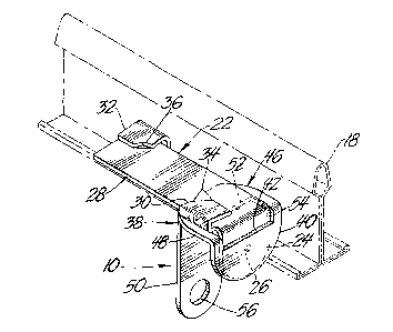
sign support assembly 10 includes an L-shaped hanger 22
for securing the assembly 10 to a track 18 of the
ceiling. The hanger 22 is formed of suitable
material, such as commercial brass, and has at one end
a depending leg or tongue 24 having a semicircular free
edge. A small hole 26 is formed in the tongue 24.
Extending from the tongue 24 is an elongate leg 28
which underlies a track 18 and has a pair of clasps 30,
32 for gripping opposite sides of a horizontal flange
- 5 -
fi J 9
~a.3~y~'..~.~_~"~
forming a part of the track 18. Each of the clasps has a
body which overlies and is spaced from the leg 28 by a
distance corresponding generally to the thickness of the
track flange. Each clasp body has one corner 34, 36 bent
upwardly to facilitate attachment of the hanger to the
track flange. The clasps 30, 32 are positioned at
opposite edges of the hanger leg 28 from one another,
with the clasp 30 adjacent the tongue 24 anc7 the clasp 32
remote from the tongue. The clasps may be bent in such
manner that they require some displacement during
attachment to the track flange so that the hanger leg is
frictionally retained on the flange.
As is shown in Figure 2, the hanger 22 is
attached to the track flange by positioning the latter
between the two clasps 30, 32 with the leg 28 underlying
and confronting the bottom of the flange. Prior to its
assembly with the track, the hanger is skewed relative to
the track 18 so that the hanger. must be rotated into
place with the corners 34, 36 of 'the respective clasps
30, 32 riding up and over opposite edges of the track
flange. When rotated into the position shown in Figure
2, the clasps 30,'32 securely retain the hanger 22 on the
track 18. In this position, the tongue 24 depends
perpendicularly from the track 18.
A sign attaching bracket, generally designated
38, is provided for attaching the sign 12 to the hanger _
22. The bracket also may be formed of commercial brass
and comprises a U- or J-shaped body having a shorter leg
- 6 -
s r~
,~9 f> ~~ :~. :~. :.~
40 and a longer leg 50 parallel to and spaced from the
leg 40 by a web 48. The length of the leg 40 corresponds
substantially to that of the tongue 24 of the hanger 22,
but the length of the web 48 is substantially less than
that of the leg 28. An opening 52 is formed in the
bracket 38 and extends partially into bath the leg 40 and
web 48. The width of the web is sufficiently great to
enable the side-to-side width of the opening 52 to
accommodate the tongue 24 freely, whereas the length of
that portion of the opening 52 in the web 48 is consider-
ably greater than the thickness of the tongue 24. The
members 22 and 38, therefore, easily may be assembled by
passing the tongue 24 through the opening 52 so that the
tongue and the shorter leg 40 confront one another and
the leg 28 confronts the web 48. The extension of the
opening 52 into the leg 40 ensures close proximity of the
tongue 24 and the leg 40.
A thermally sensitive, fusible, bonding material
42 is interposed between the confronting surfaces of the
tongue 24 and the leg 40 and secures the tongue and the
leg together. Preferably, the area of the material 42
corresponds to that of the tongue 24. The bonding
material has eutectic properties. That is, the material
is solid until it is heated to a predetermined, elevated
temperature at which it liquefies. A suitable eutectic
bonding material is composed of an allay of lead, bismuth,
and indium. The proportions of these metals can be
adjusted to provide a selected melting point, such as
-
~H~r~!~~.~~.~~
135°F, at which the material 42 liquefies, whereupon t he
bond between the members 22 and 38 is dissolved and they
may separate.
If the fire sprinkler heads 16 are selected to
be activated at an ambient temperature of between 155°F
and 165°F, the constituency of the bonding material 42
should be so selected that it will liquefy at a lower
temperature, such as between 120°F and 142°F.
The thickness of the bonding material 42 may
vary, but a thickness of approximately 0.006 inch has
been found to be satisfactory. Conventional, low
temperature soldering techniques may be used to bond the
members 22 and 38 to one another via the material 42.
Preferably, the opening 26 is filled with the material
42, thereby providing an interlock between the latter and
the tongue 24.
The longer leg 50 of the bracket member 38 has a
smoothly rounded free end adjacent which is formed an
opening 56. The level of the opening 56 preferably is
below that of the free end of the leg 40.
The apparatus thus far described is adapted to
attach the sign l2 to the ceiling track 18 in such manner
that the sign is suspended from the ceiling in an
elevated, easily seen position. The sign may be formed
in any one of a number of conventional ways, but as shown
it comprises a body 44 formed of thermally insulating
material. The body has a slot 60 in its upper edge of
such depth and width as to accommodate the longer leg 50
_ g _
f 'a
of the bracket body 38. The sign body is adapted to
accommodate a securing screw 58 which extends through the
opening 56 in the leg 50 so as to secure the sign to the
bracket 38. The sign may be secured to the bracket of
two or more of the assemblies 10 so as to provide
adequate, horizontal support for the sign.
As is best shown in Figure 4, the bracket 38 is
secured to the sign body 44 in such manner that a gap
exists between the tongue 24 and the adjacent face of the
sign body. The gap enables air to flow between the sign
l0 body and the tongue 24, thereby avoiding insulating the
tongue 24 arid ensuring adequate exposure of the bonding
material 42 to ancient temperature.
To install a sign 12, two or more hangers 22 are
assembled with and fused to a corresponding number of
brackets 38. The assembled units then are secured to the
tracks 18 at suitably spaced intervals. Thereafter, the
leg 50 of each bracket member 38 is fitted into the slat
60 of the sign body and secured therein by the screw 58.
The sign thus is suspended from the ceiling in a visible
position.
Because of the gap between the sign body 44 and
the tongue 24 the suspended sign is laterally offset from
the interface of the tongue 24, the leg 40, and the
banding material 42. This relationship creates a bending
moment between the fused riiembers 24 and 40, thus stressing
the iaonding material 42 in tension, whereas the weight of
the sign stresses the bonding material in shear. The
_ g _
tensile stress created by the bending rnornent is greater
at the free end of the ler~ 40 than at the opposite end
thereof. The bonding material has greater resistance to
tensile force than to shearing force, and has a tendency
to creep over a period of time. The tendency of the
bonding material t o creep largely is overcome by the
filling of the openir~rg 26 with the bonding material to
provide the aforementioned interlock. The greatest force
tending to separate the hanger and bracket thus is the
tensile force. As a consequence, the attachment of the
members 22 and 38, although separable, is quit a secure as
long as the temperature of the bonding material 42 is
less than the, preselected temperature.
When the ambient temperature rises to the
liquefication temperature of t he bonding material 42,
such material will liquefy, thereby enabling the tongue
24 and the leg 40 to separate from one another and l~errnit
the sign 12 and the attached bracket member 38 to fall as
is indicated in Figure 5. If the temperature thereafter
rises to the level sufficient to activate the sprinkler
heads 1s, water may flow therefrom and be unimpeded by
the sign or its brackets 38.
H significant advantage in using a bonding
material 42 having.a lower liquefi:cation temperature than
the temperature at which the sprinkler heads are activated
is that the bond between 'the hanger 22 and the bracket 38
will be dissolved prior to the emission of water from one
or more adjacent sprinkler heads. This ensures that the
-- 10
4 ,f~ (j ~ 9 ~'
~dJ !.~ j: ~. .~. e7
bonding material will not be cooled by the water emitted
from the sprinkler heads and forestalls any possibility
that such cooling will preclude separation of the sign
from its support.
The disclosed embodiment is representative of
the preferred form of the invention, but is intended to
be illustrative rather than definitive. The invention is
defined in the claims.
to
20
- 11 -