Language selection

Search

Patent 2084277 Summary

Third-party information liability

Some of the information on this Web page has been provided by external sources. The Government of Canada is not responsible for the accuracy, reliability or currency of the information supplied by external sources. Users wishing to rely upon this information should consult directly with the source of the information. Content provided by external sources is not subject to official languages, privacy and accessibility requirements.

Claims and Abstract availability

Any discrepancies in the text and image of the Claims and Abstract are due to differing posting times. Text of the Claims and Abstract are posted:

  • At the time the application is open to public inspection;
  • At the time of issue of the patent (grant).
(12) Patent Application: (11) CA 2084277
(54) English Title: METHOD AND APPARATUS FOR DETERMINATION OF MATERIAL RESIDUAL STRESS
(54) French Title: METHODE ET APPAREIL POUR DETERMINER LA CONTRAINTE REMANENTE D'UN MATERIAU
Status: Deemed Abandoned and Beyond the Period of Reinstatement - Pending Response to Notice of Disregarded Communication
Bibliographic Data
(51) International Patent Classification (IPC):
  • G01L 1/20 (2006.01)
  • G01N 3/00 (2006.01)
  • G01N 3/06 (2006.01)
(72) Inventors :
  • CHERN, ENGMIN J. (United States of America)
  • FLOM, YURY (United States of America)
(73) Owners :
  • THE GOVERNMENT OF THE UNITED STATES AS REPRESENTED BY THE ADMINISTRATOR
(71) Applicants :
  • THE GOVERNMENT OF THE UNITED STATES AS REPRESENTED BY THE ADMINISTRATOR (United States of America)
(74) Agent: MARKS & CLERK
(74) Associate agent:
(45) Issued:
(22) Filed Date: 1992-12-01
(41) Open to Public Inspection: 1993-06-03
Availability of licence: N/A
Dedicated to the Public: N/A
(25) Language of filing: English

Patent Cooperation Treaty (PCT): No

(30) Application Priority Data:
Application No. Country/Territory Date
801,141 (United States of America) 1991-12-02

Abstracts

English Abstract


ABSTRACT OF THE DISCLOSURE
A device for the determination of residual stress
in a material sample consisting of a sensor coil, adjacent
the material sample, whose resistance varies according to
the amount of stress within the material sample, a
mechanical push-pull machine for imparting a gradually
increasing compressional and tensional force on the
material sample, and an impedance gain/phase analyzer and
PC for sending an input signal to and receiving an input
signal from the sensor coil. The PC will measure and
record the change in resistance of the sensor coil and the
corresponding amount of strain of the sample. The PC will
then determine from the measurements of change of
resistance and corresponding strain of the sample the
point at which the resistance of the sensor coil is at a
minimum and the corresponding value and type of strain of
the sample at that minimum resistance point thereby
enabling a calculation of the residual stress in the
sample.


Claims

Note: Claims are shown in the official language in which they were submitted.

- 5 -
WHAT IS CLAIMED IS:
1. A method for the determination of residual
stress in a material sample comprising the steps of
placing a sensing means whose resistance
varies according to the amount of stress within said
material sample adjacent said material sample;
imparting a gradually increasing
compressional force on said material sample;
sending an input signal to and receiving an
input signal from said sensing means;
measuring and recording the change in
resistance of said sensing means and the corresponding
amount of compressional strain of said sample;
imparting a gradually increasing tensional
force on said material sample;
measuring and recording the change in
resistance of said sensing means and the corresponding
amount of tensional strain of said sample;
determining from said measurements of change
of resistance and corresponding strain of said sample the
point at which the resistance of said sensing means is at
a minimum and the corresponding value and type of strain
of said sample at that minimum resistance point thereby
enabling a calculation of the residual stress in said
sample.
2. The method of claim 1, wherein said sensing
means comprises an eddy current probe.
3. The method of claim 2, wherein said steps of
sending an input signal to and receiving an input signal
from said sensing means and measuring and recording the
change in resistance of said sensing means and the
corresponding amount of compressional and tensional strain
of said sample is implemented by an impedance gain/phase
analyzer in conjunction with a data acquisition and
analysis computer.
4. The method of claim 3, wherein said steps of
imparting a gradually increasing compressional force and a
gradually increasing tensional force on said material
sample is implemented by a mechanical push-pull machine.

- 6 -
5. A device for the determination of residual
stress in a material sample comprising:
sensing means adjacent said material sample
whose resistance varies according to the amount of stress
within said material sample;
means for imparting a gradually increasing
compressional force on said material sample;
means for sending an input signal to and
receiving an input signal from said sensing means;
means for measuring and recording the change
in resistance of said sensing means and the corresponding
amount of compressional strain of said sample;
means for imparting a gradually increasing
tensional force on said material sample;
means for measuring and recording the change
in resistance of said sensing means and the corresponding
amount of tensional strain of said sample;
means for determining from said measurements
of change of resistance and corresponding strain of said
sample the point at which the resistance of said sensing
means is at a minimum and the corresponding value and type
of strain of said sample at that minimum resistance point
thereby enabling a calculation of the residual stress in
said sample.
6. The device of claim 5, wherein said sensing
means comprises an eddy current probe.
7. The device of claim 6, wherein said means for
sending an input signal to and receiving an input signal
from said sensing means and measuring and recording the
change in resistance of said sensing means and the
corresponding amount of compressional and tensional strain
of said sample comprises an impedance gain/phase analyzer
in conjunction with a data acquisition and analysis
computer.
8. The device of claim 7, wherein said means
for imparting a gradually increasing compressional
force and a gradually increasing tensional force on
said material sample comprises a mechanical push-pull
machine.

Description

Note: Descriptions are shown in the official language in which they were submitted.


METHOD AND APPARATUS FOR DETERMINATION
OF MATERIAL RESIDUAL STRESS
Technical Field
This invention relates to Non Destructive
Inspection techniques and more particularly to a method
and device for the determination of the initial stress
state of a material specimen.
- Backqround Art
~ethods of measuring residual stresses have heen
in use for some time, and fall generally into two
categories: destructive and non-destructive. Destructive
methods required that the specimen was cut-up by hole
drilling, electrical discharge. machining (EDM), sand
blasting, or trepanning. Hole drilling was a common
method but had the undesirable feature that the drill
worked the surface locally and built-in its own stresses.
The EDM method while good was awkward to implement.
Non-destructive methods have relied on some change in
physical property when the material is stressed, e.g., the
velocity of ultrasonic waves is affected. Unfortunately
the velocity is affected far more by small variations in
matarials properties which makes the system useless for
stress measurement on anything but pure metals. X rays
have also been used but can only measure crystals near the
surface and this is a complex method which can be handled
well only in the laboratory while the real requirement is
to know the stresses over a greater depth, namely those
which would influence the initiation and propagation of
cracks.
Statement of the Invention
It is therefore an object of the present invention
to provide a method and an apparatu~ for the determina~ion
of the residual stress in materials that overcomes the
limitations found in prior art methods and devices.
The foregoing objects and others are achieved by
providing a method and apparatus for the determination of
material residual stress utiliæing three major hardware
components; a m chanical compression/tension tester, a
data acquisition/control device, and an impedance
.
.. , . - ~.
,
,
`':
: . ,: , -
... .....

- 2 - ~ 2~7
gain~phase analyzer. Other sub-components are a sensor
coil mounted on the surface of the material specimen, and
cabling to interconnect the components.
The novelty of the present in~ention lies in the
discovery that the sensor coil resistance and reactance
monotonically increases and decreases with respect to
externally applied stresses regardless of direction, i.e.,
tension or compression. I~ plotted on a graph of
resistance vs. strain, the point at which the resistance
of the sensor coil is at a minimum indicates the zero
stress state of the specimen. The residual stress is then
the strain (compression or tension) indicated on the graph
at this minimum resistance point.
In the present invention, the impedance gain/phase
analyzer, well known in the art, is connected to the
sensor coil via a cable and to the data
acquisition/control device via another cable. The
impedance gain/phase analyzer is also connected to the
mechanical test machine through the data
acquisition/control device. The data acquisition/control
device acts as the system control and is used to control
the mechanical stress/strain machine and to process data
from the impedance gain/phase analyzer. The data
acquisition deviGe/system controller can be an IBM PC or
the equivalent.
Brief Description of _he Dra~e~
Figure 1 is a graph of khe sensor coil normalized
resistance vs. strain when compression and tension is
applied to a material sample made from nickel.
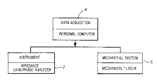
Figure 2 is a block diagram of a device according
to the present invention.
Figure 3 is a schematic diagram of a device
according to the present invention.
Detailed Description o~ the Invention
The invention consists of a method and apparatus
for determinakion of material residual stress utilizing
three major hardware components as shown in Fig. 2, which
is a block diagram of the present inventive system for
material residual stress determination. The three major
components are: a mechanical tester 6, a data acquisition
. .
.
.~

device 4, and an impedance gain/phase analyzer 2. Other
sub components, shown schematically in Fig. 3 are sensor
coil 10, mounted on the surface of material specimen 8,
and cabling 12, 14, 16.
The novelty of the present invention lies in the
discovery that sensor coil 10 resistance and reactan~e
monotonically increasesJdecreases with respect to
externally applied stresses regardless of the direction,
i.e., tension or compression. This relationship is shown
in Fig. 1 for a material sample S made from nickel where
the sensor coil 10 normalized resistance measurements,
obtained from the data acquisition device 4, are plotted
against the applied compressional and tensional forces
exerted on specimen 8 by the mechanical tester 6.
Starting from point 'IA", the point at which tester 6 is
applying no stress to sample 8 (zero applied stress
point), it can be seen that the normalized resistance of
sensor coil 10 has some positive value. As tension is
applied to sample 8, the resistance of coil 10 increases
to a maximum value at point "C". As the tension is
released, the resistance of coil 10 returns to its former
value at zero applied stress point "A"~ As compression is
applied to sample ~, the resistance of coil 10 decreases
from its value at point "A" until reaching some minimum
value at the zero stress point ~BI~o As compression
continues to be applied to sample 8, the resistance of
coil 10 will then start to increase again from point "B"
until it reaches some maximum value at point "D". The
r2sidual s~r2ss in sample ~ is thus equal to the
compressional strain imparted by tester 6 on sample 8 at
point "B", the point at which the resistance of coil 10 is
at a minimum. This point could just as easily occur at a
tensional value in other samples.
In the present invention, an impedance gain/phase
analy~er 2, such as is well Xnown in the art, is connected
to sPnsor coil 10, via cable 12, to ex~ite sensor coil 10
and to monitor its resistance, and to data acquisition
device 4 via cable 14. Impedance gain/phase analyzer 2 is
also connected indirectly ~o mechanical test~r 6 through
data acquisition device 4. Da~a acquisition d~vice 4 not
.
- .:~ .
~: :

- 4 ~ t~;~
only excites coil 10 but also acts as the system
controller and is used to control mechanical tester 6 and
to process data from impedance yain/phase analyzer 2.
Data ac~uisition device/system controller 4 can be an IBM
series 386 PC or the equivalent. An example of a suitable
impedance gain/phas~ analyzer 2 is an HP 4194A analyzer
connected by an IEEE488 bus to data acquisition
devicP/system controller 4. A typical sensor coil 10 is a
Staveley Instruments, IncO NORTEC 3551 100 kHz pencil
probe. Mechanical tester 6 can be an Instron, an MTS, or
equivalent universal tester. Cables 12, 14, lh are well
known in this art.
To those skilled in the art, many modifications
and variations o the present invention are possible in
light of the above teachings~ It is therefore to be
understood that the present invention can be practiced
otherwise than as specifisally described herein and still
will be within the spirit and scope of the appended
claims .
,
- .:
f
~: :
: ~
.

Representative Drawing
A single figure which represents the drawing illustrating the invention.
Administrative Status

2024-08-01:As part of the Next Generation Patents (NGP) transition, the Canadian Patents Database (CPD) now contains a more detailed Event History, which replicates the Event Log of our new back-office solution.

Please note that "Inactive:" events refers to events no longer in use in our new back-office solution.

For a clearer understanding of the status of the application/patent presented on this page, the site Disclaimer , as well as the definitions for Patent , Event History , Maintenance Fee  and Payment History  should be consulted.

Event History

Description Date
Inactive: IPC from MCD 2006-03-11
Time Limit for Reversal Expired 1995-06-01
Application Not Reinstated by Deadline 1995-06-01
Deemed Abandoned - Failure to Respond to Maintenance Fee Notice 1994-12-01
Inactive: Adhoc Request Documented 1994-12-01
Application Published (Open to Public Inspection) 1993-06-03

Abandonment History

Abandonment Date Reason Reinstatement Date
1994-12-01
Owners on Record

Note: Records showing the ownership history in alphabetical order.

Current Owners on Record
THE GOVERNMENT OF THE UNITED STATES AS REPRESENTED BY THE ADMINISTRATOR
Past Owners on Record
ENGMIN J. CHERN
YURY FLOM
Past Owners that do not appear in the "Owners on Record" listing will appear in other documentation within the application.
Documents

To view selected files, please enter reCAPTCHA code :


To view images, click a link in the Document Description column. To download the documents, select one or more checkboxes in the first column and then click the "Download Selected in PDF format (Zip Archive)" or the "Download Selected as Single PDF" button.

List of published and non-published patent-specific documents on the CPD .

If you have any difficulty accessing content, you can call the Client Service Centre at 1-866-997-1936 or send them an e-mail at CIPO Client Service Centre.


Document
Description 
Date
(yyyy-mm-dd) 
Number of pages   Size of Image (KB) 
Cover Page 1993-06-03 1 22
Claims 1993-06-03 2 112
Abstract 1993-06-03 1 29
Drawings 1993-06-03 3 68
Descriptions 1993-06-03 4 201
Representative drawing 1999-08-03 1 11
Courtesy - Office Letter 1993-06-08 1 50