Language selection

Search

Patent 2084495 Summary

Third-party information liability

Some of the information on this Web page has been provided by external sources. The Government of Canada is not responsible for the accuracy, reliability or currency of the information supplied by external sources. Users wishing to rely upon this information should consult directly with the source of the information. Content provided by external sources is not subject to official languages, privacy and accessibility requirements.

Claims and Abstract availability

Any discrepancies in the text and image of the Claims and Abstract are due to differing posting times. Text of the Claims and Abstract are posted:

  • At the time the application is open to public inspection;
  • At the time of issue of the patent (grant).
(12) Patent Application: (11) CA 2084495
(54) English Title: NECK
(54) French Title: GOULOT
Status: Deemed Abandoned and Beyond the Period of Reinstatement - Pending Response to Notice of Disregarded Communication
Bibliographic Data
(51) International Patent Classification (IPC):
  • B65D 8/02 (2006.01)
  • B21D 51/42 (2006.01)
  • B65D 1/20 (2006.01)
(72) Inventors :
  • COGGINGS, NIGEL EDWARD (United Kingdom)
(73) Owners :
  • TANKS AND DRUMS LIMITED
(71) Applicants :
(74) Agent: MARKS & CLERK
(74) Associate agent:
(45) Issued:
(22) Filed Date: 1992-12-03
(41) Open to Public Inspection: 1993-06-06
Examination requested: 1999-09-02
Availability of licence: N/A
Dedicated to the Public: N/A
(25) Language of filing: English

Patent Cooperation Treaty (PCT): No

(30) Application Priority Data:
Application No. Country/Territory Date
9125940.8 (United Kingdom) 1991-12-05

Abstracts

English Abstract


-10-
ABSTRACT
IMPROVED NECK
A container 10 of the type having side walls and top and bottom
ends, said top end 2 including an access hole 4 surrounded by
an upstanding neck 5 adapted to receive a suitable closure
means, wherein the neck is integrally formed from the material
of the top end. There is also provided a closure means 12
comprising a cap having a top 13 and a skirt 15 extending
downwardly therefrom, the skirt having an internal thread
to engage the external thread of the neck, wherein the top 13a
of the cap is formed in a concave shape, the opposite surface
13b being convex and extending downwardly towards the interior
of the cap.


Claims

Note: Claims are shown in the official language in which they were submitted.

-7-
The embodiments of the invention in which an exclusive
property or privilege is claimed are defined as follows:
1. A container of the type having side walls and top and
bottom ends, said top end including an access hole surrounded
by an upstanding neck adapted to receive a suitable closure
means, wherein the neck is integrally formed from the material
of the top end.
2. A container according to Claim 1, wherein the material for
the neck is provided by the pressing out of the access hole in
the container top end.
3. A container according to Claim 1 wherein the integrally
formed neck has a thread pattern either cut afterwards or
integrally formed during the formation of the neck.
4. A container according to Claim 1 wherein the uppermost edge
of the integrally formed neck is turned over internally of the
neck.
5. A container according to Claim 1 wherein the diameter of
the access hole is substantially greater than that or a
conventional container access hole.
6. A container according to Claim 5 wherein the access hole is
between 10cm and 13cm (4 inches to 5 inches approximately).
7. A container according to Claim 1 wherein the access hole is
located in the centre of the container end.
8. A container according to Claim 1 wherein there is included
a pivoted handle mounted to the container end, by plates
located on either side or the neck, for pivotal movement about
an axis which corresponds to a diameter of the container end.
9. A closure means for use with a container according to claim

-8-
3. comprising a cap having a top and a skirt extending
downwardly therefrom, the skirt being internally threaded to
engage the external thread of the neck, wherein the top of the
cap is formed in a concave shape, extending convexly towards
the interior of the cap.
10. A closure means according to Claim 9, wherein there is
provided a seal which runs around the perimeter of the cap,
between the concave top and the skirt,
11. A closure means according to Claim 9 wherein the edge of
the cap skirt is turned over to form a rolled safe edge.
12. A container and container closure assembly comprising a
container according to claim 1 and a closure means according to
Claim 11, wherein the container end is formed with an annular
groove running around the outside of the neck, this groove
receiving the rolled safe edge of the cap when the latter is
secured to two neck.
13. A container and container closure assembly according to
Claim 12, wherein the container end includes a second annular
groove, running around the neck exteriorly of the first-
mentioned groove.
14. A container and container Closure assembly comprising a
container according to Claim 1 and a closure means according to
Claim 9 wherein there is provided an alternative closure means
in the form of a plastic cap having a pouring spout or tube,
which may be screwed on to the neck, in place of the previously
described cap, for dispensing small quantities of liquid.
15. A method of manufacturing a container of the type having
side walls, top and bottom ends, said top end including an
access hole surrounded by an upstanding neck adapted to receive
a suitable closure means, wherein the method includes the step
of integrally forming the neck from the material of the top

-9-
end.

Description

Note: Descriptions are shown in the official language in which they were submitted.


~SP~D ~o~
~hi~: inv~an~ion relate~ to ~n i2provcd neck f or use with cans,
tanks or drums.
Dn:lms for ca~ing li~uids are c:ommonly provided with a screw
cap closure me4ns. An upstar.O.Lng externally ~reaCLod neck on
the ~op end of t~e drum pro~ride~; acce~s to the int4~ior ~f~ th~
drum, and a cc~mple~erl~ary ~crew cap having a wad o~ seal n its
inner face completes ~he closllro. ~h~i3 maxi~ n diam~t~ o~
this conven~onal neck is in the region of 70 ~.
conven~ionally, the neck is formed separately and is crimped or
othorwic!c~ j oined to the edge of a pressed hole in the top ~nd
~f the drum. It has ~een f~und ~at this con~,rentional
~oh3truction of dr~ neck can f~ he t~ drop test, in ~rhich
the illed with liS~id and closed with a suitable closure
mean3 is dropped f,om a predetermined height. orten, ~urin~
thi~ test, the joint between the ne~k and the drum end fails.
It i~ thereiore the aim or ~he p~eser,t invention to provi~e a
drum neck which overcomes this; di~:ad~ran~gQ, and also ovQrcomes;
the rs~trlctions cause~ ~y the rela~ively small diameter neck~
According to a ~irst ~spect of the present invention ~her~ is
provid~d a~ container of the type he~ving sidc w~lls ~nd top ~nd
bottom ends, said top end including an upst:andihg neck adapted
to recei~e ~ :sui~blc clo~u~e ~:eans, wherein thc n~ck is
integrally formed ~rom ~he material of the ~o~ end.
era~l~, ~Le material for ~he nec3c is provided ~y the
pr~:~slng ~ut Or the hole w~ prov~des access to the ~rum.
Thi~ may conve~iently be achie~ed by arranging for the hole
pressed out ~ contain6~ top c~nd to b~ larg~ ~ar~ with
convention~l containers of this type. T~is pro~,rides
i~nt mate~ial to ~:imultaneously form a rai~3ed, integral
ne~k ~y pressing, heat ~or~ing o~ othe~ su~table process. The

-2~ *
larg~r ~ole also allows air to ~nter the c:ontain~r at the s~me
time as tlle 11qula ls pouxed out, ~e~Ul'clng ln muc~ s~oot~ler
f lo~i~
~h~ int~gr~lly form~d n~ek ~ay hav~ a d~ired t}lr~ad ~satt~n
eitlher cut afterwards or integrally form~d during ~he p~essing
~te.~ge. Thi~ thre~d pA~ter~ m~y ~o~ ex~ple be ~ull, bayonet
or ;multistart.
The size of the hole to be ~ressed can ~e varied according to
the size or the drum and the height o~ the neck req~ired, but
a typical hole diameter would be between lOc:~ ~nd 13c~
inc21es to 5 inches app~oxlmatelx~ for a ~ 11 inch) diameter
drum with erlds: formed $ram ~in plate and/ or steel .
The ~ntlsrgrally form~3d n~ck romov~s ~h4 need fo:r a second nec3c
~itting operatio~, and there is no weak points where a
n~rention~l neo3c wculd have been ~itt~d.
~he l~rge!r holc, ~ wcll e~s providin~ ~aterial for the int~gral
neck, also permits easy ~illing and emptying of the container,
And ~ p~r~its th~ in~.rtion of ~ mixi~g de~i~e, pump or
othQr tool.
Ihe c~ntainer having a neck according to the present invention
is pre~erably ~i~ted with a closure means co~prisin~ a cap
h~vi~g a top and a ~ki~t ~xt4naing downwaxdly therefrom, the
skirt b~ing internally threaded to ehgage the external threa~
of the ne~k, wherein the top o~ the cap is form~d in a ~oncav~
shape, ex~ending convexly to~ards the interior o~ the cap. A
~eal is pre~erably provided, which runs ~rou~d the perimeter of
the cap~ between the conc~ve top and the skirt. Conveniently
~he edge of the ~ap skirt i~ turned ~er ~o form a rolled safe
~d~e.
In the preferred embodimen~ of the invention, the container end
~s ~ormea wstn an ~nnular groove runnin~ arouna t~e outside of

1L r~
the ~oSe
~n. n~rm~iP~,~ ~ ~ .
seal pre ~ t~
e ~nnu;~r~ ~e- ;~ssure i~ e~ cc~n;t~i~
incre~ b:2=
thi has~
. i r~
~ ~-~e ~
. ~
,,,, A~lothe~ ~Y~"~
C~
Conv~~ r'~
? ~ m~y a~:s,5g~ro~' d~
t ~ . ,~-~"~ ~ a.po~g~
e ,~ j'~,,.D,~ ;thR ne~."~ 21ace -o~
previousl~
~reviO~ F~
f i~ted ~i~o~n~rc-~ns, ;shoil~ ~e~
t ranspO~ ; 2~ Da~, ~ or-~ -.tho
In zl C~ ; too~ 7frf~

r~
~4-
an~ a rlx~ nan~le ls ~olne~ to ~he centre o~ the drum end.
With the provision ef a larger neck in a~ordance with thepreferred e~bodiment of this inventio~, 1t ls convenient to
locat~ thi~ l~rg~r hol~ .in th~ eQntr~ of the dr~m e.~, t~hi~h
simlplifies au~omatic filling and to ihclude a pivoted handle
~or pivoting movement ~bou~ an axi~ whi~h aorr~pondc to a
diame~er Of the drum end, the har.dle being pivotally mounted to
the drum end by pl~te~ loc~ted on either 8ide o~ the ~eck~
Pre:~er~Dly the uppe;~most edge o~ thè :integr~lly forDIed neck i9
~urned over intern~lly at ~he neck, for strength, improved
emptying ability and sarety.
Acco~d1ng to a seCond aspect of the present ~nvention there is
provid~a a m~thod ~f manufacturing a cont~iner ~ the type
having side walls, top and bot~om ends, and an upstanding neck
ada;?t61d to r~c~3iv~ a ~:uita~l~ olo~:urc~ wher~in th~ ~thoa
includes the step of integrally forming the neek from the
material of the top end~
Whil~t it i~ on~i4~ged th~t t~i~ in~cntion will prim~ily b~
a~licable ~o ~ontailler~ of generally cylindrical
configuration, it is equally applicable to any type of
con~ainer of the general type described abo~e.
Embodim4ntc of th4 pr4~ent invcntion will now be described ~y
way of exa~ple only with reference to the accompanying dra~lngs
in whieh ;-
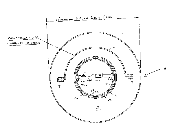
Figure 1 i~ top plan ~ieu of a drum having ~n in~egral n~ck andclosure according to the invention;
Fi~ure 2 i5 a side view o~ ~he integral neck; and
Pigure 3 is an exam~le o~ ~ ~uitable closure means for use with
the necx Of ~ne present lnv~nt10n.

~1 A ~
--5--
R~fe:rri~g to th~ dra~ings, a con~ainer according to tne present
in~ention takes the ~or~ o~ a ~en~rnlly cyli~drl~al 25 litre
capacity drum de6ignated generally by lo. ~e drum naS a
cyl~ndrical side wall, a bott~m end (no~ 3hown) and a t~p end
2.
Access to the d~ via a~ cç~ntral hole 4 in the top en~L 2
whiGh is surr~unded b~ an u~standing nec~ 5 integrQlly ~ormQd
with the ~rum end 2 fro~ the matQrial pro~ided by the pressing
out o~ hole 4. A ~i~oting handle 7 is ~ttached to ~he drum
en~ by pivo~ pla~es 8,9 so a:3 ~o pivot about a dia~Leter of 'che
drum G~ 2. ~his handle 7 can be pivoted to lie ~lat ag~in~t
the drum end 2 on elther ~id~ of the h~l~ 4, to ~ovide
umob~ ructed acc~ o the neck 5~
Figu:~e 2 illustra~a~ th4 integrally fo ~ ed necX 5 in more
detail, and in par~:icul~r the ~yone'C threzld pa~ern 5a and ~he
e~ge 5b which i3 turned ov~r internally of the neck 5.
The cap 1~ illus~ratcd in Fiyur~ 3 ~aS a top 13 and ~ skir~ 15
~xte~din~ do~nwardly fro~ the ~op. The ~kirt 15 h~s an
in~ernal bayonet th~a l~a whia~h is ~o~ple~entary ~o the
thread 5a of the ~eck, and a rolled s~fe edge 12b. ~ flow~d
in gaske~ seal l~ runs ar~ung ~hc peri~Qt~r.
The ~pper surface 13a o~ t~e ~ is conca~e, succh ~hat its
opp~sit~ ~ur~ce 13~ i~ convex and exte~ds downwardly in~o ~he
ne~k 5 whe~ the cap is screwed on to the Ileck Pu~ing flexing
o~ cap top 13, thc ~idewall ~3c 0~ the cap is pushed outwardlyt
causinsl ~he se2~ o ~e presse~ more tlg~tly ~g~Linst: edge Sb
of nec~ ~.
The top end ~ o~ the dru~ has two a~nul~r grooves ~a ~nd 2b
running around the neck 5.
~he ~ir~t g~oov~ 2a recei~es the rolled safe e~gè 12b of the
cap ~2, to hold the e~ge or the c~p c~p~iv~ against lateral,

;~ r~
--6--
splaying forc~. Tho s~cond groo~e ab act~ to hal~ or~ or
~ault llnes whi~h tend to ~Qrm in the en~ ~ during a pressure
su:rge, thu~: ~ainta.ining t}~e n~ nd its closure intact an~L
un~istorted.
B~ause the cap does not h2ve to ~e destroyed to gain access to
th~ oont~iner, the cont~ine~s andtor ~h¢ caps can be laundered
~nd re-used, providing en~lronmental benefits.
The uppe~ surface 13a of the ~ap is fitt~d with a m~t~l 6trip
20 whic~ ~s spot welaed to the cap at 20a,20b~ This per~its
a tQ~que wren~h to b4 u~Qd to tight~n the cap to tbe requ~i rea
pressu~e.

Representative Drawing
A single figure which represents the drawing illustrating the invention.
Administrative Status

2024-08-01:As part of the Next Generation Patents (NGP) transition, the Canadian Patents Database (CPD) now contains a more detailed Event History, which replicates the Event Log of our new back-office solution.

Please note that "Inactive:" events refers to events no longer in use in our new back-office solution.

For a clearer understanding of the status of the application/patent presented on this page, the site Disclaimer , as well as the definitions for Patent , Event History , Maintenance Fee  and Payment History  should be consulted.

Event History

Description Date
Inactive: IPC from MCD 2006-03-11
Application Not Reinstated by Deadline 2000-12-04
Time Limit for Reversal Expired 2000-12-04
Deemed Abandoned - Failure to Respond to Maintenance Fee Notice 1999-12-03
Letter Sent 1999-09-28
Inactive: Application prosecuted on TS as of Log entry date 1999-09-28
Inactive: Status info is complete as of Log entry date 1999-09-28
Request for Examination Requirements Determined Compliant 1999-09-02
All Requirements for Examination Determined Compliant 1999-09-02
Application Published (Open to Public Inspection) 1993-06-06

Abandonment History

Abandonment Date Reason Reinstatement Date
1999-12-03

Maintenance Fee

The last payment was received on 

Note : If the full payment has not been received on or before the date indicated, a further fee may be required which may be one of the following

  • the reinstatement fee;
  • the late payment fee; or
  • additional fee to reverse deemed expiry.

Please refer to the CIPO Patent Fees web page to see all current fee amounts.

Fee History

Fee Type Anniversary Year Due Date Paid Date
MF (application, 5th anniv.) - standard 05 1997-12-03 1997-11-17
MF (application, 6th anniv.) - standard 06 1998-12-03 1998-11-20
Request for examination - standard 1999-09-02
MF (application, 2nd anniv.) - standard 02 1994-12-05
Owners on Record

Note: Records showing the ownership history in alphabetical order.

Current Owners on Record
TANKS AND DRUMS LIMITED
Past Owners on Record
NIGEL EDWARD COGGINGS
Past Owners that do not appear in the "Owners on Record" listing will appear in other documentation within the application.
Documents

To view selected files, please enter reCAPTCHA code :


To view images, click a link in the Document Description column. To download the documents, select one or more checkboxes in the first column and then click the "Download Selected in PDF format (Zip Archive)" or the "Download Selected as Single PDF" button.

List of published and non-published patent-specific documents on the CPD .

If you have any difficulty accessing content, you can call the Client Service Centre at 1-866-997-1936 or send them an e-mail at CIPO Client Service Centre.


Document
Description 
Date
(yyyy-mm-dd) 
Number of pages   Size of Image (KB) 
Cover Page 1994-01-19 1 12
Abstract 1994-01-19 1 15
Claims 1994-01-19 3 71
Drawings 1994-01-19 2 41
Description 1994-01-19 6 316
Drawings 1999-10-14 2 33
Representative drawing 1999-03-19 1 17
Reminder - Request for Examination 1999-08-04 1 127
Acknowledgement of Request for Examination 1999-09-28 1 193
Courtesy - Abandonment Letter (Maintenance Fee) 2000-01-04 1 185
Correspondence 1993-10-07 3 93
Fees 1994-11-25 1 48
Fees 1996-11-19 1 81
Fees 1995-11-28 1 51