Note: Descriptions are shown in the official language in which they were submitted.
Specification
The invention reiates to a process for the filling andclosing of vessels, preferably of bottles with a
liquid, in which vessel filled in a filling means are
closed with a closure element with deformation of the
closure element or/and of the vessel and with the
formation of a sealing press fit between the closure
element and the vessel and a device for the carrying
out of the process, the device comprising accordingly a
filling means for the filling of the vessel and a
closure means for closing of the vessel with a closure
element.
Such processes and corresponding devices are above all
used in the beverage industry for filling and closing
bottles, a so-called crown cap being mostly used as
closure element. In order to ensure a long-term pre-
servability of the filled beverages, high requirements
must be met by the tightness of the closure. According-
ly, a high sealing pressing pressure is necessary
between crown cap and the bottle to be closed. This
high sealing pressure is achieved by pressing the crown
cap with a great force, e.g. 80 kp, against the opening
edge of the bottle in the closure device, and a
deformation of the crown edge of the crown cap is
effected in such fashion that the crown cap is fixed to
the bottle in the pressed position. Accordingly, the
construction of the closure means must be designed in
such fashion that correspondingly high pxessing
pressures can be produced. Restrictions result from
this requirement with respect to the minimally
achievable dimensions of the closure device, and in
particular the minimally achievable overall height.
-
2~78~
Consequently, the closing processs within the closure
device can only be carried out at a relative distance
from the filling means due to its great dimensions in
conventional devices for the filling and closing o~
vessels, the result of this being that the filled
bottles still remain open over a relatively long period
of time, and the liquid contained therein is exposed to
the ambient air. The influence of the a~bient air can
substantially impair the long-term preservability and
the taste of a filled beverage.
Therefore it is aimed at providing closure devices
which can be installed as near to the filling means as
possible or which can be integrated in the filling
means so that the closing of the vessels can be carried
out as directly after the filling as possible. Such
closure means are described in the publications DE-AS
20 42 328, DE-PS 23 13 268, DE-PS 22 53 985, US 3 759
012 and US 2 695 743. There is the disadvantage in the
case of an integration of the closure means in the
filling means that, in the case of a bottle breaking
(due to high closure pressures), considerable disturb-
ances of the operating sequence occur.
-
It is known from DE-OS 14 32 416 to first of all only
place closure elements consisting of flat lids on the
vessel openings~ for covering the vessel openings
r: directly after the filling and to feed the vessels with
the loosely placed lids to a closure means. There is
the risk, in particular at high working speeds, that
the loosely placed lids can slip down from the vessels.
It is the object of the invention to provide a process
of the type mentioned at the beginning, in which a
higher quality and, in particular, long-term
.
. .
- : ,
.
-- --
.
2~a7~
preservability of the filled products result as
compared with known processes and a device for carrying
out the process, no increased constructional
expenditure for reducing the closure means or for its
integration in the filling means being necessary.
The process according to the invention is characterized
in that the closure element (21) is affixed in a first
closing phase to form a slight sealing press fit and a
sealing press fit is produced in a second closing phase
with the final sealing pressing pressure. Accordingly,
the closure means of the device according to the
invention comprises a first means for affixing the
closurP element to the vessel with the formation of a
slight sealing press fit and a second means for pro-
ducing a sealing press fit with the final sealing
pressing pressure.
It can be achieved by this solution according to the
invention that the vessels can be closed by the first
means in such fashion that the liquid contained therein
is no longer subjected to the ambient atmosphere while
the vessels are fed to the second means for the final
closing.
Thus, the second means can be installed at a distance
from the filling means, and there are no restrictions
as reqards its overall height. The first means only-
provided for affixing only requires a small overall
height and can thus be advantageously installed direct-
ly at the vessel outlet of the filling means. By
keeping the a~bient atmosphere away from the liquid
between the filling and the final closing of the
vessels, there is no impairment of the quality of the
liquid such as of the taste and the long-term
.^. .- ^, ~ '.`;?
v, ~ ., ~
preservability of a filled beverage. It is ensured by
the slight press fit produced in the first closing
phase during the filling of e.g. carbonated beverages
that the carbon dioxide can escape from the bottles,
and there is not the risk as in closure lids which are
only placed on the bottles that the closure elements
are lifted by the emerging carbon dioxide from the
vessel opening and can fall down.
In advantageous development of the invention, the
closure element, preferably a crown cap can be pre-
shaped in suited fashion by a snap or lock fit for the
producing of a slight sealing press fit in the first
closing phase. However, it is also possible to plastic-
ally deform the closure elements directly during the
first closing phase for producing the slight press fit.
In a preferred example of embodiment the filling means
is designed as a carousel filling means, and the first
means for the first closing phase comprises an affixing
means with supports for the closure elements, which
engages into the base circle of the carousel filling
means at the vessel outlet. The affixing is carried out
in such fashion that the vessels disposed in the
carousel filling means on elevating tables below
filling valves, which can be pressed against the
filling valves by means of the elevating tables are
pressed by means of the elevating tables from below
against the closure elements held in the supports of
the affixing means, the vessels hàving been lowered in
advance with respect to the filling valves to such an
extent that the affixing means can engage into the
interstice between the vessel and the filling valve.
The vessel with the affixed closure element are trans-
ferred to a transport means designed as rotary disk at
2~7~3
the outlet of the filling means, by means of which the
vessels can be supplied to a second means, disposed at
a distance from the filling means on a transport orbit
for the final closing of the vessels.
Further advantageous development possibilities of the
invention are revealed by the sub-claims.
It is provided in one of these development possibili-
ties that the affixing head comprises at least three
pin elements which are shaped with a seat cross-section
substantially tapered in accordance with the shape of
the crown cap edge at the end facing the crown cap edge
for the formation of a seat aligning the crown cap for
affixing.
It is achieved by this development that the crown cap
is held on the affixing head in a defined position so
that if the affixing head and the vessel to be closed
have been brought into the closing position, an exact
alignment between crown cap and vessel is ensured. In
the affixing head known from the prior art, an exact
alignment of the crown caps on the affixing head is
very difficult.
In the affixing head designed in this fashion the crown
cap must not directly rest against the magnetic
support. Instead of a sprung affixing head which yields
during the affixing head, the magnetic support can be
disposed in rearward staggered fashion wi~h respect to
the seat position of the crown cap.
In the case of the use of three pins it is ensured that
the crown cap rests against respectively one pin at
~ v ~
three points, and thus a non-tilting, centered seat is
thus ensured.
A deformation of the crown cap edge which is especially
suited for affixing the crown cap is attained, since it
is provided in a further advantageous development of
the invention that the pins are undercut in their
portion adjoining the cone end and are in particularly
conically tapered.
A guide path can be provided below the revolving
affixing heads to supply the crown caps to the affixing
heads. Crown caps introduced into this guide path from
a storage container can either be received by a movable
affixing head being lowering towards the crown cap or
the crown caps are supplied to an affixing head which
comprises a deformation pin with an extension which
serves as a carrier for the crown cap in the guide
path. The crown cap is pushed onto an oblique ramp by
the carrier and lifted into the area of action of the
magnetic support.
It is provided in a further advantageous development of
~ the invention that the means comprises a pneumatic
driving means for the affixing head. It is ensured by
this solution that the affixing process can be carried
out at an extraordinarily high speed with sufficient
pressing pressure so that only little time is required
for affixing the crown caps.
It is advantageous if the driving means comprises at
least a pressure cylinder with a piston guided therein.
Affixing heads revolving in the fashion of a -carousel
are preferably provided, to which a pressure cylinder
with piston is in each case allocated and which are
:~ : :
~ .
,
-.
.
:
- - . ' : '-
.' ' ' ', ~, ,: ,
. .,: . :
.
7 ~ 3
7 ~
movable for t~e affixing of the crown caps into the
bottle conveyor path of the filling means, preferably a
carousel filling means, so that they intersect or are
tangent to the conveyor path. Due to the high speed of
the affixing process which can be attained accordinq to
the invention, the affixing heads must only be aligned
to the bottle openings over a very short path section,
and no reduction of the bottle conveying speed is
required for carrying out the affixing process.
The pressure cylinders allocated to the revolving
affixing heads are preferably connected to a disk cam
comprising passage ducts for the pressure gas which are
connectable to the pressure gas source and opening to
the interior of the cylinder, the passage ducts being
connectable to the pressure gas source via a sliding
block with a pressure gas feed duct opening towards a
sealing slide surface, whose opening end can be covered
by the disk cam with abutment against the sealing slide
surface and can be connected with the opening ends of
the passage duct, which do not face the pressure
cylinders.
The cross-sectional surfaces of each passage duct and
the cross-sectional surface of the pressure gas suppply
duct are advantageously dimensioned at least at their
opening ends, which can be connected with each other,
in accordance with a desired time sequence of the
affixing process.
The cross-section of the pressure gas supply duct is
suitably smaller than the cross-section of the passage
duct at least at the outlet opening facing the disk
cam. Due to this, the sealing of the pressure gas
supply duct against the disk cam is facilitated with
2~7~3
the given dimensions, if no connection to a passage
duct is establishe~, since the sealing slide surface is
large as compared. with the outlet opening of the
pressure gas supply duct in the sliding block.
In a further advantageous development of the invention
the sliding block is connected with a piston guided in
a pressure cylinder, the end of the pressure gas supply
duct not facing the disk cam ending in the interior of
the cylinder. An auxiliary spring can additionally act
on the piston for the optimum control of the pressing
force of the sealing surfaces against the disk cam.
The invention will now be explained and described in
greater detail by means of examples of embodiment and
the enclosed drawings relating to these examples of
embodiment.
Fig. 1 shows an example of embodiment for a device
according to the invention (schematical),
Fig. 2 shows an example of embodiment for a means
according to the invention for the affixing of crown
caps in a first closing phase (in details),
Fig. 3 shows a means for supplying caps to the affixing
means according to Fig. 2,
Fig. 4 shows a means for the final closing of a bottle
with an affixed crown cap according to the invention,
Fig. 5 shows a crown cap affixed to a bottle according
to the invention in a means for the final closing of
the bottle,
,
.
.
: . , ,. . ' ', ' . ' : ~ ' ~ . ' :
. .
: . : - ... .
- - -
2 ~ 3
g
Fig. 6 shows a crown cap on a bottle after the final
closing of the bottle,
Fig. 7 shows a crown cap as it has been used so far for
the closing of bottles in one operation,
Fig. 8 shows a first example of embodiment of a pre-
shaped crown cap as it can be used in a device accord-
ing to the invention for the closing of bottles in two
phases,
Fig. 9 shows a second example of embodiment of a crown
cap usable in a device according to the invention,
Fig. 10 shaws a third example of embodiment of a crown
cap usable in a device according to the invention,
Fig. 11 shows a fourth example of embodiment of a crown
cap uæable in a device according to the invention,
Fiq. 12 shows a device for re-shaping a conventional
crown cap to a crown cap usable in the process accord-
ing to.the invention (schematical),
Fig. 13 shows a second device for reshaping a conven-
tional crown cap to a crown cap usable in the process
according to the invention,
Fig. 14 shows a further example of embodiment of a
device for the re-shaping of a conventional crown cap
to a crown cap usable in the process according to the
invention (schematical),
.. ~ . ... ' ~ -
':
.
.
.
- lo - 2 ~ ~ ~ 7 8 3
Fig. 15 shows an affixing means for the affixing of a
crown cap to a bottle according to the invention with
plastic deformation of the crown cap (schematical),
Fig. 16 shows a further example of embodiment for a
means for the affixing of a crown cap to a bottle
according to the invention with plastic deformation of
the crown cap in a position prior to the affixing
(schematical), and
Fig. 17 shows the means of Fig. 16 in a position during
affixing;
Fig. 18 shows an example of embodiment of a device
according to the invention for the filling and closing
of vessels schematically in a detail,
Fig. 19 shows a lateral view of an example of embodi-
ment of an affixing head according to invention,
Fig. 20 shows a rear view of the example of embodiment
of Fig. 19.
Fig. 21 shows a lateral view of the example of embodi-
ment according to Figs. 19 and 20 during the affixing
of the crown cap,
Fig. 12 shows an example of embodiment of a deformation
pin according to the invention,
Fig. 23 shows an example of embodiment of a deformation
pin according to the invention with an extension
serving as a carrier.
.
.
, ' , ~ ' ~ ' ' ' ~
' , ' ' . .
-- . .
:,
2 ~ ~7 ~ ~
Fig. 24 shows an example of embodiment for an affixing
means for affixing crown caps with individually movable
affixing heads revolving like a carousel, and
Fig. 25 shows a detail of a top view of the affixing
means according to Fig. 24,
Fig. 26 shows a schematical detail of an example of
embodiment for a device according to the invention for
the filling and closing of vessels,
Fig. 27 shows a lateral view of an example of embodi-
ment for an affixing head,
Fig. 28 shows a rear view of an example of embodiment
of Fig. 27,
Fig. 29 shows a lateral view of the example of embodi-
ment according to Figs. 27 and 28 during the affixing
of a crown cap,
Fig. 30 shows the example of embodiment of a deforma-
tion pin,
Fig. 31 shows an example of embodiment of an affixing
means according to the invention as it can be used in a
device according to the invention for the filling and
closing of vessels according to Fig. 26, and
Fig. 32 shows an example of embodiment for a sliding
block usable in the affixing means according to the
invention of Fig. 1 for the supply of compressed air.
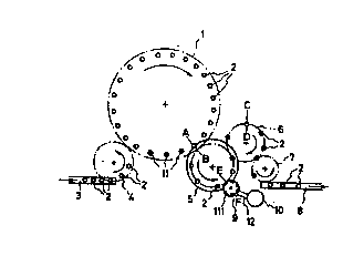
A filling means is designated with the reference
numeral 1 in Fig. 1, which is designed as a carousel
'
.
- . .
- , . :
. - - :
-
2~3~7~3
- 12 -
filling means in the present example of embodiment.
Vessels, in the present case bottles, are disposed on
elevating tables 11 provided in distributed fashion
- accross the circular circumference in the filling
means, which can be pressed with their filling openings
against filling valves disposed above the elevating
tables (not shown in Fig. 1) by means of the elevating
tables. Bottles are fed to the carousel filling means 1
via an inlet system, the inlet system comprising an
inlet belt 3 and a rotary transport disk 4, the bottles
2 being transferred to the rotary transport disk 4 from
the inlet belt 2, which conveys them to the filling
means 1. A rotary transport disk is designated with 5,
to which the filled bottles are transferred at the
outlet of the filling means and which conveys them to a
further rotary transport disk 6. A means (not shown in
Fig. 1) for affixing crown caps to the bottles filled
during the revolution in the carousel filling means is
provided at the point of intersection designated with
A-B. A means (not shown in Fig. 1) for the final
closing of the bottles with further deformation of the
affixed crown caps is disposed peripherally at the
point of the rotary transport disk 6, which is desig-
nated with C-D. The finally closed bottles finally get
into an outlet system which comprises a rotary trans-
port disk 7 to which the closed bottles are transferred
~from the rotary transport disk 6 and which convéys them
to an outlet belt 8. A feeding means for crown caps is
designated with 9, which feeds the crown caps from a
storage reservoir 10 via a guide 12 and a deformation
means 111, which will be described more exactly by
means of Fig. 13 in the following, to the affixing
means (not shown in Fig. 1). The affixing means com-
`~ ~prises a rotary disk which is coaxial to the rotary
transport disk 5, at which supports disposed on a
:~
.:: . .
.
' ~ ' "' . . '.
.
- 13 - 2 ~ 7 ~ 3
circular circumference are provided for the crown caps
fed via the feeding means.
Details of this rotary disk of the affixing means are
represented in Fig. 2 and it is designated with the
reference numeral 13. As is furthermore revealed by
Fig. 2 the rotary disk 5 comprises an upper guide
element 14 and a lower guide element 15, the guide
elements comprising guide slots at their periphery into
which the bottles to be transported can be introduced.
Guide arcs are respectively designated with 14a and
15a, by means of which the bottles are held in the
guide slots. As is revealed by Fig. 2, the rotary disk
13, the upper guide element 14 and the lower guide
element 15 engage into the main circle of the filling
means, where the elevating tables 11 supporting the
bottles are disposed. A filling valve connected with a
filler tank 18, respectively disposed above each
elevating table 11 and rotating with it is designated
with 16 in Fig. 2, which comprises a centering bell 17
at its lower end.
During the filling process the bottles 2 are pressed in
each case against the centering bell by the elevating
table ll. The condition at the bottle outlet of the
filling means in shown in Fig. 2, in which the bottles
are completely filled and lowered with respect to the
centering bell 17 by lowering the elevating table 11.
The rotary disk 13 engages in the interspace between
the centering bell 17 and the upper end of the bottle
2, at which crown caps are held at predetermined points
by means of magnetic effect in the present example of
embodiment. At the point in time at which the crown cap
fed by the rotary disk 13 is aligned to the opening of
the bottle 2, the elevating table 11 is moved upwards,
.
:
.
2~ 783
~ 14
and the bottle is pressed into the crown cap with an
elevating force of about 20 kp in the present example
of embodiment for affixing. In order to ensure such an
affixing, the cap is preshaped in suited fashion.
Suited pre-shapings will be explained more exactly in
the following by means of Figs. 5 to 14. Since the
guide path of the crown cap and the guide path of the
elevating tables 11 do not correspond to each other,
wear phenomena occur at the affixing point. By means of
additional guide means (not shown in Fig. 2) the guide
paths can be caused to match during the affixing
process avoiding such a wear by ensuring, e.g. by
suited guide rail, that the path of the bottle is
adapted to the path of the crown cap during the affix-
ing process.
It is especially advantageous if the diameter of the
rotary disk 13 is selected smaller than that of the
rotary disk 5 or of the guide elements 14 and 15, and
their axis of rotation is disposed eccentrically with
respect to that of the guide elements 14, 15 in such
fashion that the indexing circles of the filling
carousel, the guide elements 14 and 15 and the rotary
disk 13 oYerlap each other at the point designated with
A-B in Fiq. 1. Due to this, a bottle can be kept
axially~clamped between the centering bell 17 and the
elevating table 11 until it has safely entered the
guide elements 14, 15, before the centering bell 17 is
lifted or~the elevating table is lowered so that the
rotary disk 13 can engage between bottle head and
filling valve for the delivery of the cap. It is
furthermore advantageous to drive the rotary disk 13
with a cylindriGal lantern gear which is connected to
its top and which meshes with the guide rods of the
centering bells 17 at the filling carousel, whereby an
'
2~3~7~3
- 15
extremely exact synchronous running at the moment of
the affixing of the cap on the bottle is attained,
which is of advantage for the centering accuracy~
It is shown in Fig. 3 how the crown caps are fed to the
rotary disk 13 by a feeding means 9 comprising a
deformation means 111. Crown caps arriving at the
outlet of the deformation means 111 are introduced into
a recess 19 in the rotary disk by attracting the crown
caps via magnetic forces acting on the support point
near the recess 19. A bottle 2 transported on a sliding
sheet 20 by the rotary disk 5 is shown in Fig. 3, whose
crown cap 21 is already affixed. The rotary disk 13
conveys the crown cap taken over to the affixing point
in the same direction of rotation with which the rotary
disk comprising the upper guide element 14 and the
lower guide element 15 transports the bottle 2.
The bottle 2 with the affixed crown cap 21 is conveyed
by the rotary disk 5 until transfer to the rotary disk
6, where the means for the final closing of the bottle
is disposed.
The means used for tha final closing of the bottles is
shown in Fig. 4. The reference numeral 22 designates in
Fig. 4 a closure element for ths final closing of the
bottles with the affixed crown cap, the closure element
being formed by a sleeve 22a, in which a holding-down
means 23 which is cushioned against the closure element
by a spring 25 is disposed. The sleeve of the closure
element 22 has a closure cone 24 at its lower end. ~he
closure element is guided in a rotating bearing plate
26 and comprises a wheel or a cam 28 which engages into
a recess of a stationary lifting cam 27.
.
~ 16 - 20~7~3
Due to its being guiding in the rotating support 26,
the closure elemen~ 22 can follow the path of the
bottle 2 moved by the rotary transport disk. The
closure element 22 is moved downwards for the closing
since the wheel 28 engaging into the lifting cam lowers
the closure element 22 in accordance with the cam
profile. In the present example of embodiment a force
of about 80 kp is exerted on the crown cap by the
holding-down means 23, this force being active prior to
and during the pressing down of the closing cone 24 for
flanging the crown edge of the crown cap by the sleeve
22a.
The condition directly prior to the final closing of
the bottle 2 is shown in Fig. 5. The crown cap 21
affixed to the bottle 2 with a sealing insert 29 is
connected with the bottle 2 by a lock fit active in the
area 30 of the crown edge of the crown cap. The sealing
pressing pressure necessary for the final closing is
produced by the holding-down means, in the present
example of embodiment 80 kp of the sealing pressing
pressure necessary for the final closure, and the crown
cap is flanged by the sleeve 22 of the lowered closure
element as shown in Fig. 6. Due to the flanging, the
pressing pressure produced by the holding-down means is
substantially preserved, and the bottle is sealed
~as-tightly.
Fig. 7 shows a crown cap as it is conventionally used
for the closing of bottles. The crown edge of the crown
cap has an inclination of about 3% in the centre of the
width, and the inner diameter of the crown cap exceeds
the outer diameter of the bottle to be closed by about
O.5 mm in the centre of the crown edge. A crown closure
suitably preshaped for use in the process of the
2~7~3
~ 17
invention is shown in Fig. 8. As is revealed by Fig. 8,
the crown edge is not inclined in the centre with
respect to a direction vertically to the base portion
of the crown cap, and the inner diameter of the crown
cap is by about o,l mm smaller than the outer diameter
of the bottle to be closed approximately in the middle
of the crown edge. Such a crown cap can be affixed in
the fashion described in Fig. 2 forming a snap or lock
fit between the crown cap and the bottle to be closed
in a first closing phase of the bottle.
A further preformed crown cap suited for affixing is
shown in Fig. 9. Recesses 31 are pressed into the crown
edge of the crown cap by means of which inwardly
projecting dents are formed~ Due to these inwardly
projecting dents, the cap can be affixed to a bottle
forming a snap or lock fit.
A further crown cap affixable in a first closing phase
is shown by Fig. 10. The crown cap 21 comprises a
sealinq insert 34 with a central lug 33. A snap or lock
fit can be produced between the central lug 33 and the
inner edge of the opening of a bottle 35, whereby the
crown cap 32 can be affixed to the bottle 35 in a
first closing phase.
A further possibility for the suited deformation of a
conventional crown cap is revealed by Fig. 11. The
crown cap is crimped at opposite points of the crown
edge. A crimping could also be effected at further,
preferably opposite points.
A device is schematically shown in Fig. 12, with which
such indentations can be produced. For deformation, a
crown cap 37 is guided throuqh opposite deformation
~: -
.
~ 18 - 2 ~ 7 ~ 3
rollers 135 and 36 rotating in the opposite direction
of rotation, the deformation rollers having deformation
cams 38 to 42 by means of which the crown edge of the
crown cap can be crimped in the fashion explained by
means of Fig. 11, a preshaped crown cap with three
indentations being produced in the present case.
A means is shown in Fig. 13 which serves for reshaping
a conventional crown cap to a crown cap according to
Fig. 11. Such a reshapi,ng means is contained in the
feeding means shown in Fig. 1 where it is designated
with the reference numeral 111. The crown caps fed via
the guide 12 are guided between two deformation wheels
43 by a rotary disk 44 comprising peripheral carrier
slots, which are laterally closed by a guide arc 45 in
the transport area of the carrier plate, a lateral
indentation of the crown caps being carried out. A
holding-down rail is designated with 46, which makes an
exact guiding of the crown cap on a crown cap support
47 possible during deformation. A magnetic support is
designated with 48 in Fig. 13, which is disposed on the
rotary disk 5, to Which the preshaped crown caps are
transferr-d.
A possible device by means of which the crown caps can
be~produc-d~in~similar fashion as in the example shown
in~Fig.~8 is~ shown in Fig. 14. The inner diameter of
the~crown~caps is uniformly narrowed by pressing the
crown~caps through~a sleeve 49 which has a correspond-
ingly suited inner diameter.
An affixing process is revealed by Fig. 15, which is
s~imilar~to~the described~process,for the final closing
of~the~bottles. A~bottle 53 with a conventional crown
cap~;52 placed on top of it ls pressed against a
:, ~ : .
-
":
- . ' . : , . -
'2 ~ 3
- 19
holding-down means 50 which is disposed in a deforma-
tion sleeve Sl. The difference to the closing process
for the final closing of the bottles which is revealed
by Fig. 4 consists in that the inner diameter of the
deformation sleeve 51 is selected in such fashion that
only a slight press fit is produced between the bottle
53 and the crown cap 52.
Figs. 16 and 17 reveal tht the affixing can al90 be
carried out by pressing a bottle 57 against a conven-
tional crown cap held by a magnetic support 54, lateral
deformation pins 56 flanging the crown edge of the
crown cap 58 in places and producing thereby a lock fit
of the cap on the bottle. In the shown example of
embodiment, the magnetic support 54 is connected with a
rotary disk 53 via a spring 55 which corresponds to the
rotary disk 13 shown in Figs. 2 and 3.
The deformation means included in the device in the
present example of embodiment could also be provided
separately from the device.
Embodiments having affixing heads with at least 3 pins
will be described in the following by means of Figs. 18
to 25.
A carousel filling means i5 designated in general with
the reference numeral 201 in Fig. 18, a marginal detail
of which is represented in Fig. 18. Elevating tables
205 are disposed on the circular conveyor path desig-
nated with 204 in the carousel filling means, on which
bottles 202 to be filled are deposited. The bottles can
be pressed by means of the elevating tables 205 within
the filling means 201 against filling valves (not shown
in Fig. 18). An affixing means is designated in general
- ~ , - :
, . . .
: . . . ' ,
.
.
:
.
.
. .
.. . .
- 20- 2~8~7~ 3
with 203, which comprises a rotary disk 206. Affixing
heads are disposed on the rotary disk 206 on a circular
circumference, of which magnetic plates 207 inserted
into the rotary disk 206 are visible in Fig. 18. The
rotary disk 206 with the af~ixing heads engages in such
fashion into the conveyor path 204 of the filling means
that the paths of the bottles conveyed on the elevating
tables 205 of the carousel filling means 201 and the
paths of the affixing heads rotated with the rotary
disk 206 intersect each other in an area, in which an
affixing of crown caps can be carried out. A guide path
is designated with 208, by means of which the crown
caps can be guided laterally below the rotary disk 206
and then under the rotary disk for a distance along the
revolving path of the affixing heads. The feed of crown
caps to the affixing heads via this guide path 208 will
be explained in greater detail in the following by
means of Fig. 19.
A further rotary disk is designated with 209 which
comprises recess pockets 209a on the disk edge for the
bottles 202. A lateral bottle guide is designated with
210, which engages in the conveyor circuit 204 of the
carousel filling means like the rotary disk 209 with
its pockets 209a, and is stationary with respect to the
carousel lfilling means, the rotary disk 209 and also
the rotary disk 206. A further lateral bottle guide is
designated with 211, which engages into the xevolving
path of the bottles in the rotary disk 209 and feeds
the bottles to a means (not shown in Fig. 18) for the
final closing. Drivîng means for the rotary dis3c 206
and the rotary disk 209 and synchronizing means for
synchronizing the rotation of the rotary disk 206 and
the rotary disk 209 with the rotation of the carousel
filling means are also not shown in Fig. 18.
. . . .
--
2~7~3
_ 21
An affixing head is represented in Figs. 19 to 21 as it
can be used in the device shown in Fig. 18. One holding
magnet 207 in the form of a stepped round disk is
embedded in the rotary disk 206 per affixing head. In
the present example of embodiment deformation pins 213
to 215 projecting vertically from the rotary disk are
provided in each case at the same distance to the
central axis of the disk and disposed in accordance
with the corners of an equilateral triangle, which will
be explained in greater detail in the following by
means of Fig. 20 and 21. Of the three deformation pins
the pin 215 comprises an extension 216 which projects
beyond the length of the pins 213 to 214. A ramp is
designated with 218 which is formed on the guide path
208 shown in Fig. 18. The ramp comprises two spaced
rail elements between which the extension 216 of the
deformation pin 215 is moved. A crown cap is designated
with 217 in Figs. 19 to 21, which is carried along by
the extension in the guide path and is lifted in the
direction to the magnetic support by the ramp rising in
the direction of conveyance. The pins 213 to 215 have
cone surfaces tapered in the direction of the crown
caps, which form a seat for the crown cap.
A pin as it is used for the pins 213 and 214 of the
affixing head shown in Fig. 19 and 20 is shown in Fig.
22. The pin comprises a shank 219 (not shown in Fig. 19
and 20), via which the pin is anchored in the rotary
disk 206. The deformation pin 213 comprises a cone
surface 220 whose inclination to the pin axis is
preferably about 30 and is approximately adapted to
the shape or the inclination of a crown cap edge to be
affixed. The pin portion 221 adjoining the cone 220
has a slightly conical tapering in the direction of the
. . ~
.
2~7~
22
shank 219. The end edges 222 and 223 of the cone 220
are rounded.
The deformation pin 215 shown in Fig. 23 corresponds to
the pin 213 shown in Fig. 22 with respect to the
elements 219a, 220a, 221a and 22a designated with the
same reference numerals. As opposed to the pin 213, the
pin 215 has an extension 216, which is conically
tapered to the pin end in the present example of
embodiment. A transition edge 224 is rounded between
the cone 220a and the extension 216.
The filled bottles feed-conveyed on the circular
conveyor line 204 of the carousel filling means are
pressed against the affixing heads of the rotary disk
203 for affixing the crown caps by means of the elevat-
ing tables 205 provided in the carousel filling means.
The movement of the rotary disk 206 with the affixing
head is effected synchronously to the rotation of the
.
carousei filling means so that the affixing heads are
approximately caused to coincide with the bottle
openings via~a small rotary angle of the rotary disk
206~or the carousel filling means so that the affixing
oan be carrled out. It~ could~be ensured by additional
guide~means~so that the paths of the bottles and of the
affix1ng~heads~are~adapted to each other over a some-
what'~greater~r~otary~angle. If the bottles are pressed
against the~ affixing heads for the affixing of the
cro~wn~caps~by~means~of the elevating tables, the edge
of the~crown cap~is~bent~inwardly in pIaces as shown in
Fig~ 2~1 at~the~points~where the deformation pins abut,
whereby~the bottom~oP the crown cap is pressed against
th~bottlé~opening~with'a pressing force sufficient for
a~sl1ght afflYlng~ closure of the bottles by means of
the~bending~res1stance~of the crown cap edge. It proved
.
.
2~7~
- 23 -
to be advantageous for the suited deformation of the
crown caps for an affixing closure that the pin por-
tions adjoining the crown cap cone are undercut, and
are conically tapered in the shown examples of embodi-
ment. Due to this, the ejection of the bottles from the
affixing heads is not disturbed upon the lowering of
the elevating tables 205 caused by the backspringing of
the deformed crown cap edge. The ejection of the
bottles from the affixing heads could alternatively
also be supported by the fact that a delimitation for
the advance of the bottles during the affixing is
provided in such fashion that the crown cap edge also
abuts against a seat surface of the pin elements
forming the seat with the tapered seat cross-section in
the advance end position of the pin elements. The
backspringing force of the deformed crown cap thus acts
on an oblique plane and promotes an automatic sliding
of the affixed crown caps out of the affixing heads.
In the shown example of embodiment the side of the
magnetic support facing the crown cap is flush with the
rotary disk. The magnetic disk could also be staggered
rearwards or proejct so much that the lifting height
necessary for the affixing of the crown cap is ensured.
It would also be conceivable that the magnetic disk
projects up to the edge 222 or 222a of the cone 220 or
220a as a maximum, and the magnetic disk is movable
upwards against spring force and/or its weight.
Directly after the affixing of the crown caps, when the
bottles are again lowered to the normal transport
plane, the lateral bottle guide 210 engaging into the
conveyor path 204 ensures that the bottles with the
affixed crown cap leave the carousel filling means and
and are further transported by the rotary disk 209
. - . . - - .
,: ' . ,, . :
. ' ' ' ~ . . - .
., ~ .. ..
,. , :
- .,
.
2~78~
24
guided by the lateral guide 210. The movement of the
rotary disk 209 is synchronized to the rotation of the
carousel filling means in such fashion that the trans-
fer of a bottle from an elevating table 205 of the
carousel filling means to a poc~et 209a of the rotary
disk 209 can be effected in each case. The bottles with
the affixed caps are further transported to the rotary
disk 209, where they stand on sliding surfaces (not
shown) until they are gripped by the lateral guide 211
and supplied to the closure means for the final closing
of the bottles with the production of the final sealing
pressure of the crown caps.
During the supply of crown caps to the affixing heads
via the guide path 208, crown caps are supplied in
radial direction, one crown cap being gripped in each
case by the extension 216 of the deformation pin 215
and pushed onto the ramp shown in Fig. 19. The crown
cap 217 is lifted and gets into the range of action of
the magnetic holding means 207, which pulls it into the
seat formed by the cone surfaces 220 or 220a of the
pins 213 to 215. Since the cone surfaces are adapted in
their inclination approximately to the inclination of
the crown cap edge and, moreover, the deformation pins
are adapted to the shape with the crown cap edge with
their roundings, an exact alignment and holding is
achieved~by the seat formed by the three deformation
pins in the present example of embodiment. This exact
alignment is necessary to achieve an exact alignment of
crown cap and bottle opening if the bottle and the
affixing head are superimposed for affixing the crown
cap. Due to the feeding of the crown cap via the ramp
and the corresponding proportioning of the magnetic
force of the magnetic disk 207 it is ensured that the
magnetic force is only active at the moment when the
. . ,
2~3~7~3
- 25 -
exact alignment of the crown cap in the seat formed by
the cone surfaces of the deformation pins is already
largely completed.
An alternative affixing means is shown in Fig. 24 which
comprises affixing heads 225 revolving like a carousel,
which are movable individually vertically for the
affixing of the crown caps. A valve means is designated
with 226 in Fig. 24 which forms part of a carousel
filling means and rotates synchronously to the elevat-
ing tables 205 for a bottle 202 in the carousel filling
means. A cylindrical lantern gear connected to the
affixing means for synchronizng the rotary movement of
the affixing means with the rotation of the carousel
filling means is designated with 227, which meshes with
cylindrical portions of the alve means 227. The affix-
ing heads 225 are connected with a central rotary
element 230 via a carriage means 31, the carriage means
31 being guided vertically and fixed for co-rotation on
the central rotary element and displaceably upwards
against the force of a spring 229. The guided carriages
rest with their lower end on a stationary disk cam
228, by means of which a vertical movement of the
carriages, and thus of the affixing heads, can be con-
trolled. A lateral feeding path for the crown caps is
designated with 232 in Fig. 18, into which a further
guide path described in greater detail in Fig. 25 ends.
The guide path designated with 233 is disposed below
the affixin~ heads 225 and adapted to the path of the
affixing heads.
The affixing means shown in Figs. 24 and 25 could be
used instead of the rotary disk shown in Fig. 18. In
this case, however, the affixing of the crown caps is
: ~ . . . . .
. .
.. . .. . .. . . . ..
.
2l~8~A7$,.J
- 26 -
not carried out by a lifting movement of the elevatingtables 205, but by a vertical movement of the affixing
heads controlled via the disk cam 228. It is ensured by
means of the cylindrical lantern gear 227 that an
affixing position results in each case, in which the
bottles 202 and the affixing heads 225 for affixing the
crown caps are aligned to each other.
In the affixing means shown in Figs. 24 and 25 the
affixing heads are not supplied via a ramp provided in
the guide path 233 and an elongated deformation pin,
but the affixing heads are in each case lowered down to
the individual crown caps entering the guide path 233
from the guide path 232 by means of the disk cam 228.
An alignment of the crown caps in the seat formed by
the cone surfaces of the deformation pins takes place
during the lowering, and the magnetic supports 207a
ensure that the crown caps remain in the seat if the
affixing heads are again lifted from the guide path. In
the example of embodiment for an affixing head accord-
ing to Figs. 24 and 25, a cap supply via ramps could
certainly also be carried out as this was described by
means of Fig. 21.
Examples of embodiment are described in the following
Figs., which work with pneumatic drives for the affix-
ing head. The fundamental construction corresponds to
that already described by means of Fig. 18.
Fig. 26 corresponds to Fig. 18, however, additional
pressure gas passage ducts are designated with 334 in
Fig. 26, which are provided in the disk cam and are in
each case allocated to one of the affixing heads
connected with the disk cam 306. The openings of the
- . -
~ V ~ i 'J V
- 27 -
pressure gas passage ducts are connectable with a
pressure gas source (not shown in Fig. 26) via a
stationary sliding block 33s by rotating the disk cam
306, which will be explained in greater detail in the
following by means of Figs. 31 and 32.
An affixing head is represented in Figs. 27 to 28 as it
can be used in the device shown in Fig. 26. A holding
magnet 307 in the form of a stepped round disk is
embedded in an affixing head carrier plate 336. De-
formation pins 313 to 315 projecting vertically from
the affixing head carrier plate are disposed in the
present example of embodiment in each case at the same
distance to the central axis of the disk and in accord-
ance with the corners of an equilateral triangle, as
they are described in greater detail by means of Fig.
30. A crown cap is designated with 317 in Figs. 27 to
28, which can be supplied to the affixing head via the
guide path 38 shown in Fig. 26, the af~ixing heads
being e.g. lowered so much onto the guide path that the
crown caps get into the range of action of the holding
magnets 307. The pins 313 to 315 have cone ends taper-
ing in the direction of the crown cap, which form a
seat for the crown cap.
A pin as it is used for the pins 313 to 315 of the
affixing head shown in Figs. 27 and 28 is shown in
detail in Fig. 5. The pin has a shank 310 (in each case
not shown in Figs. 27 to 28), via which the pin can be
anchored in the affixing head carrier plate 336. The
deformation pin has a cone surface 320 whose inclina-
tion to the pin axis is preferably approx. 30 and
which is approximately adapted to the shape or inclina-
tion of a crown cap edge to be affixed. The pin portion
321 adjoining the cone 320 has a slight conical taper
., ' . .
'. ' ' ' ' ~
.
2~3~733
28
in the direction of the shank 19. The end edges 322 and
323 of the cone 320-are rounded.
-
A disk cam with passage ducts 334a is designated withthe reference numeral 306a in Fig. 31. Several pressure
cylinders 337 in accordance with the number of passage
ducts 334a are provided on the lower side of the disk
cam 306a, which are disposed on a circular circumfer-
ence, the passage ducts 334a being open towards the
interior of the compressed-air cylinders. One piston
338 each is guided in the compressed-air cylinders,
which is connected in each case with an affixing head
carrier plate 336a. Deformation pins connected with the
carrier plate 336a and forming the affixing head are
designated with 313a to 315a, and a magnetic plate
embedded into the carrier plate is designated with
307a. The piston rod of the piston 338 is guided in a
guide sleeve 339 provided in the cylinder 337 and
fastened by means of a ring 347. The piston 333 can be
moved against a helical spring 340, which rests with
its one end against the edge of the piston 338, which
projects beyond the piston rod, and with its other end
against the edge of the guide sleeve 339, which faces
the piston~ The cylinders 337 are in each case provided
as recesses in blocks 341 connected with the disk cam
306a in pressure-sealed fashion. A guide pin 343
connected with the affixing head carrier plate is in
each case guided in a further recess 342 in the blocks
341 via a guide sleeve 344.
A central carrier element is designated with 34~, on
which the disk cam with the affixing heads connected to
it is rotatably mounted via bearings 348 and 349.
2 ~ 8 t~
-
A filling bell of a valve means is designated with the
reference numeral 350 in Fig. 31, which co-rotates
synchronously with bottles 302a in the carousel filling
means, which are deposited on elevating tables (not
shown in Fig. 31) for lifting the bottles against the
filling bell.
A feeding means (not shown in Fig. 31) held stationari-
ly and horizontally on the disk cam 306a for the
feeding of compressed air is shown in Fig. 32. The
means comprises a cylinder 359 which is disposed fixed
for co-rotation with respect to the disk cam 306ai in
which a piston 357 with a sealing ring 360 is guided.
The piston 3S7 is connected with a piston rod which is
designed as a sliding block 356 supported on the disk
cam 306a. The piston 357 and the sliding block 356
connected with it are provided with a bore 362 which
opens at one end to the interior of the cylinder 359
and at the other end to the sealing slide surface, with
which the sliding block 356 rests against the disk cam
306a. A feed line is designated with 355, via which the
~interior of cylinder 359 can be connected with a
compressed-air source (not shown in Fig. 32). The wall
of thé~cylinder 359 is designed in such fashion at the
cylinder end facing the disk cam 306a that a guiding of
the sliding block~356 is ensured. A helical spring 3S4
ls~disposed~in the interior of the cylinder which rests
with~onc~end against the piston 3S7 and with the other
end~against the front wall of the cylinder 3S9.
A~condition is represented in Fig. 32, in which the
disk cam 306a is disposed in such fashion with respect
to~the feeding means that the passage opening 334a is
in communication with the bore 362. The disk cam 306a
with;th- affixing heads moves synchronously with the
: ~: :
, .
.. - - . .. . .
.. . : . : .... , - . : .
. . ~ .
- - - : : .. ,.. ,, . , . .. : .. -. . .
-: ...... .: : ...... . : . . : ~. :
.. .': ' '' ,'.: ; ,: , . :. . ' .' '' ' . -
- 2
- 30 -
carousel filling means in such fashion that the
affixing heads for affixing the crown caps are in each
case aligned over the conveyed, just filled bottles,
the affixing heads engaging into the interspace between
the filling bell 350 and the bottles 302a lowered with
respect to the filling bell. The compressed-air feed
means is disposed on the disk cam 306a in such fashion
that a passage duct 334a is in each case in communica-
tion with the bore 363 when the affixing head with the
crown cap 317a supplied previously to it has arrived
above a bottle to which the crown cap is to be affixed.
Since compressed air can enter the cylinder 337 via the
respective passage ducts 334a, the piston and the
affixing head connected thereto are moved in a direc-
tion vertically to the longitudinal axis of the bo~tle,
and the crown cap is affixed to the bottle 302a by this
movement. Due to the additional guide of the affixing
head carrier plate 336a via the pin 343 torques are
absorbed which occur due to the fact that the affixing
head is disposed in staggered relationship with respect
to the piston 338 in a horizontal direction~ In the
case of a further rotation of the disk cam 306a, the
connection between the bore~362 and the passage duct
~ 334a is interrupted again and the piston 338 is pressed
upwards by the helical spring 340 so that the affixing
head is lifted from the bottles with the crown cap
having been~af~fLxed in the meantime. After the affix-
;ing,~ the bottles 302a are transferred to the rotary
disk~309 shown in Fig. 26 and by means of it they are
supplied~to the means for the final closing of the
~bottles. In order to receive the crown caps supplied on
the~guide path 308, the affixing heads, controlled by a
cam path (not shown in Fig. 31) against the force of
the spring 340 to the guide path 308, are lowered to
the guide path 308 so that the crown caps get into the
. :
: - . - .. : -
. ~ : ' . ' . : . :
. . . - , : , .
... ' . . . .
: . ' ' .: , :. . . :
~- , . , :
2a~7~?.
- 31 -
range of action of the magnetic disk 307a and are thus
pulled into the seat formed by the guide pins. An
affixing head is shown in such a lowered position on
the righthand side of Fig. 31. The crown cap supply to
the affixing heads could also be carried out via a ramp
on the guide path 308 as described above.
The cross-sections of the bore 362 and of the passage
ducts 334 are designed in such fashion that the ti~e
sequence of the piston movement and the pressing
pressure development during the available closing time,
i.e. the ti~e during which the affixing heads and
bottles revolving on different paths are aligned
exactly to each other in a fashion suited for affixing,
a reliable affixing of the crown caps is ensured. The
acting of pressure on the pistons 338 is carried out
during the time in which the bore 362 is in communica-
tion with the respective passage duct 334a.
Shape and dimensions of the cross-sectional surfaces of
the passage ducts 334a and the bore 362 can be suitably
dimensioned in such fashion at least at their end
openin~s facing each other that a specific, desired
chronological coordination of the advance movement and
the pressing pressure development of the affixing heads
is achieved.
It is ensured by the auxiliary spring 354 that a
sufficient pressing pressure is present between the
sliding block and the disk cam, even if a pressure drop
occurs in the interior of the cylinder when the opening
ends of the bore 362 and a respective passage duct 334a
overlap.
,
- ' ' : ' ' , , ' ,
- , ,
. -': - ' : ' ' ~
--