Language selection

Search

Patent 2084829 Summary

Third-party information liability

Some of the information on this Web page has been provided by external sources. The Government of Canada is not responsible for the accuracy, reliability or currency of the information supplied by external sources. Users wishing to rely upon this information should consult directly with the source of the information. Content provided by external sources is not subject to official languages, privacy and accessibility requirements.

Claims and Abstract availability

Any discrepancies in the text and image of the Claims and Abstract are due to differing posting times. Text of the Claims and Abstract are posted:

  • At the time the application is open to public inspection;
  • At the time of issue of the patent (grant).
(12) Patent: (11) CA 2084829
(54) English Title: SKATE BOOT WITH MOULDED PLASTIC OVERLAY
(54) French Title: CHAUSSURE DE PATIN MUNIE D'UN RECOUVREMENT EN PLASTIQUE MOULE
Status: Expired and beyond the Period of Reversal
Bibliographic Data
(51) International Patent Classification (IPC):
  • A43B 5/16 (2006.01)
(72) Inventors :
  • HOSHIZAKI, T. BLAINE (Canada)
  • ACHESON, JEFFREY J. (Canada)
  • BLACK, GERALD (Canada)
(73) Owners :
  • BAUER INC.
(71) Applicants :
  • BAUER INC. (Canada)
(74) Agent: SMART & BIGGAR LP
(74) Associate agent:
(45) Issued: 1999-04-20
(22) Filed Date: 1992-12-08
(41) Open to Public Inspection: 1994-06-09
Examination requested: 1992-12-08
Availability of licence: N/A
Dedicated to the Public: N/A
(25) Language of filing: English

Patent Cooperation Treaty (PCT): No

(30) Application Priority Data: None

Abstracts

English Abstract


A skate boot is described, having a plastic overlay
sewn or otherwise secured to the boot of the skate, wrapping
around the heel of the boot from the medial to the lateral
side of the ankle. The overlay increases the rigidity of the
rear of the skate, to restrict pronation and supination, while
adding impact resistance. Preferably, in order to permit
dorsal and plantar flexion, the plastic overlay has several
cut-out areas which allow for a controlled amount of flexion
about a lateral axis, namely a heel flex cut-out area and side
flex cut-out areas on either side in the instep area.
Flexible inserts are preferably installed in the cut-out
areas, to maintain extra impact protection while permitting
flexion.


French Abstract

Cette invention concerne une chaussure de patin dont la tige comporte un revêtement en plastique cousu ou autrement maintenu en place autour du talon et allant de la partie médiane à la partie latérale de la cheville. Ce revêtement accroît la rigidité de l'arrière de la chaussure pour limiter les mouvements de pronation et de supination tout en offrant une protection supérieure contre les chocs. De préférence, le revêtement comporte plusieurs découpures destinées à permettre la flexion dorsale et la flexion plantaire du pied en autorisant une flexion limitée autour d'un axe transversal. Il s'agit notamment d'une découpure au talon et de découpures latérales de chaque côté du cou-de-pied. De préférence, des inserts élastiques sont posés dans les découpures pour assurer une meilleure protection contre les chocs sans restreindre les mouvements de flexion.

Claims

Note: Claims are shown in the official language in which they were submitted.

THE EMBODIMENTS OF THE INVENTION FOR WHICH AN EXCLUSIVE
PROPERTY OR PRIVILEGE IS CLAIMED ARE DEFINED AS FOLLOWS:
1. A skate boot having a back portion and side portions,
said skate hoot comprising a rigid overlay wrapping around
a substantial portion of said back portion and said side
portions, said rigid overlay comprising a first cut-out
area across said back portion at approximately the area of
the malleoli of a person wearing the boot, said rigid
overlay further comprising second and third cut-out areas
on each said side portions, said second and third cut-out
areas extending forwardly from an area adjacent the areas
of the malleoli of a person wearing the boot to a forward
edge of said overlay.
2. A skate boot as defined in claim 1, wherein said
first, second and third cut-out areas, as viewed from the
side of said boot, are generally V-shaped, the apexes of
said V-shaped areas being directed generally towards the
areas of the malleoli of a person wearing the boot, thereby
facilitating flexion of the boot around axes corresponding
to the areas of the malleoli.
3. A skate boot as defined in claim 1, wherein said
first, second and third cut-out areas comprise flexible
inserts, said inserts accommodating a compression or
expansion of said rigid overlay.
4. A skate boot as defined in claim 1, wherein said rigid
overlay further comprises fourth and fifth cut-out areas on
said side portions near said back portion, said fourth and
fifth cut-out areas extending from below the areas of the
malleoli of a person wearing the boot to a lower edge of

the overlay, said fourth and fifth cut-out areas inherently
reducing the weight of said rigid overlay.
5. A skate boot as defined in any one of claims 1 to 4,
wherein said inserts comprise corrugations.
6. A skate boot as defined in any one of claims 1 to 4,
wherein said overlay is made of plastics material.
7. A skate boot comprising a discrete overlay of
synthetic material fixedly secured to the boot and wrapping
around a substantial portion of the back of the boot from
a medial to a lateral side, said overlay having at least
three cut-out areas, namely one in the area across the back
of the boot at approximately the area of the malleoli of a
person wearing the skate, and one on each of the medial and
lateral sides of the skate from a point adjacent the
malleoli and opening forwardly therefrom.
8. A skate boot as defined in claim 7, wherein said
cut-out areas have flexible inserts secured therein across said
cut-out areas which permit compression or expansion within
said cut-out areas.
9. A skate boot as defined in claim 1, wherein said
overlay is made of plastics material.
10. A skate boot as defined in claim 7, wherein said
first, second and third cut-out areas, as viewed from the
side of said boot, are generally V-shaped, the apexes of
said V-shaped areas being directed generally towards the
areas of the malleoli of a person wearing the boot, thereby
facilitating flexion of the boot around axes corresponding
to the areas of the malleoli.

11. A skate boot as defined in claim 7, wherein said
first, second and third cut-out areas comprise flexible
inserts, said inserts accommodating a compression or
expansion of said rigid overlay.
12. A skate boot as defined in claim 7, wherein said rigid
overlay further comprises fourth and fifth cut-out areas on
said side portions near said back portion, said fourth and
fifth cut-out areas extending from below the areas of the
malleoli of a person wearing the boot to a lower edge of
the overlay, said fourth and fifth cut-out areas inherently
reducing the weight of said rigid overlay.
13. A skate hoot comprising a discrete overlay of
synthetic material fixedly secured to the boot and wrapping
around a substantial portion of the back of the boot from
a medial to a lateral side, said overlay having at least
three cut out areas, namely one in the area across the back
of the boot, a second one and a third one on each of the
medial and lateral sides of the skate and opening forwardly
therefrom.
14. A skate boot as defined in claim 13, wherein at least
one of said cut-out areas has a flexible insert secured
therein across said cut-out.
15. A skate boot as defined in claim 13, wherein said
second and third cut-out areas extend to a forward edge of
said overlay.
16. A skate boot as defined in claim 13, wherein said
overlay is made of plastics material.

Description

Note: Descriptions are shown in the official language in which they were submitted.


208~29
This invention relates to ice skates, and especially
but not necessarily exclusively to those used for ice hockey.
In ice hockey, it is essential for the player to
have a skate which is as rigid as possible, especially in
terms of resistance to supination and pronation, i.e. movement
about a longitudinal axis of the foot. Such rigidity provides
the player with direct control over the skate blade edges,
which is essential to controlled, balanced and powerful
skating.
At the same time, the skate cannot be too rigid,
particularly in terms of dorsal and plantar flexion, i.e.
movement about a lateral axis, because the player has to be
able to flex his ankle normally, to maximize power and
control.
Also, since injury to the foot and ankle through
impact is always a concern, whether through impact from a
hockey puck or via a deliberate or accidental slash from a
hockey stick, impact protection is highly desirable.
It is therefore an object of the invention to
provide a skate which improves the overall strength and
rigidity of the skate boot, particularly in terms of
restricting supination and pronation, i.e. movement about a
longitudinal axis.
It is a further object of the invention to provide
improved impact protection.
Preferably, the invention restricts supination and
pronation, but permits a certain amount of dorsal and plantar
flexion, i.e. movement about a lateral axis.

Thus, as embodied and broadly described herein, the
invention provides a skate boot having a back portion and
side portions, said skate boot comprising a rigid overlay
wrapping around a substantial portion of said back portion
and said side portions, said rigid overlay comprising a
first cut-out area across said hack portion at
approximately the area of the malleoli of a person wearing
the bcot, said rigid overlay further comprising second and
third cut-out areas on each said side portions, said second
and third cut-out areas extending forwardly from an area
adjacent the areas of the malleoli of a person wearing the
hoot to a forward edge of said overlay.
In a preferred embodiment, said first, second and
third cut-out areas, as viewed from the side of said boot,
are generally V-shaped, the apexes of said V-shaped areas
being directed generally towards the areas of the malleoli
of a person wearing the boot, thereby facilitating flexion
of the boot around axes corresponding to the areas of the
malleoli. Preferably, said first, second and third cut-out
areas comprise flexihle inserts, said inserts accommodating
a compression or expansion of said rigid overlay.
In a further aspect, the rigid overlay further
comprises fourth and fifth cut-out areas on said side
portions near said back portion, said fourth and fifth cut-
out areas extending from below the areas of the malleoli of
a person wearing the boot to a lower edge of the overlay,
said fourth and fifth cut-out areas inherently reducing the
3~ welght o~ said rigld overlay.
As embodied and broadly described herein, the
lnvention also provides a skate boot comprising a discrete
overlay of synthetic material fixedly secured to the boot
and wrapping around a suhstantial portion of the back of

:7 ~ ~ 6 ~ ~ ~
the boot from a medial to a lateral side, said overlay
having at least three cut-out areas, namely one in the area
across the back of the boot at approximately the area of
the malleoli of a person wearing the skate, and one on each
of the medial and lateral sides of the skate from a point
adjacent the malleoli and opening forwardly therefrom.
Preferably, the cut-out areas have flexible inserts
secured therein ~cross said cut-out areas which permit
compression or expansion within said cut-out areas.
Most preferably, the first, second and third cut-out
areas, as viewed fro~ the side of said boot, are generally
V-shaped, the apexes of said V-shaped areas being directed
1~ generally towards the areas of the malleoli of a person
wearing the boot, thereby facilitating flexion of the boot
around axes corresponding to the areas of the malleoli.
Preferably, the said rigid overlay further comprises
fourth and fifth cut-out areas on said side portions near
said back portion, said fourth and fifth cut-out areas
extending from below the areas of the malleoli of a person
wearing the boot to a lower edge of the overlay, said
fourth and fifth cut-out areas inherently reducing the
2~ weight of said rigid overlay.
As embodied and broadly described herein, the
invention provides a skate boot comprising a discrete
overlay of synthetic material fixedly secured to the boot
and wrapping around a suhstantial portion of the back of
the boot from a medial to a lateral side, said overlay
having at least three cut out areas, namely one in the area
across the bac~ of the boot, a second one and a third one
on each of the medial and lateral sides of the skate and
opening forwardly therefrom.
2b
,,

h ~
Preferably, at least one of said cut-out areas has a
flexihle insert secured therein across said cut-out.
Most preferably, said second and third cut-out areas
extend to a forward edge of said overlay.
2c
,~ $

208~829
In the invention, therefore, a relatively thick and
therefore somewhat inflexible plastic overlay is sewn or
otherwise secured to the boot of the skate, wrapping around
the heel of the boot from the medial to the lateral side of
the ankle. The overlay increases the rigidity of the rear of
the skate, while obviously adding impact resistance.
Preferably, in order to permit dorsal and plantar
flexion, the plastic overlay has several cut-out areas which
allow for a certain amount of such flexion. For example, a
heel flex cut-out area may be provided, and side flex cut-out
areas may be provided on either side near the dorsal or instep
area. Flexible inserts may be installed in the cut-out areas
if desired, to maintain extra impact protection while
permitting flexion.
Further features of the invention will be described
or will become apparent in the course of the following
detailed description.
In order that the invention may be more clearly
understood, the preferred embodiment thereof will now be
described in detail by way of example, with reference to the
accompanying drawings, in which:
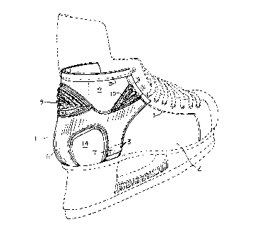
Fig. 1 is a perspective view of a skate with the
preferred configuration of plastic overlay;
Fig. 2 is a side view of the skate;
Fig. 3 is a back view of the skate;
Fig. 4 is a plan view of the overlay, laid out flat;
Fig. 5 is a section at A-A of Fig. 4;
Fig. 6 is a section at B-B of Fig. 4;

2081829
Fig. 7 is a section at C-C of Fig. 4;
Fig. 8 is a section at D-D of Fig. 4;
Fig. 9 is a section at E-E of Fig. 4;
Fig. 10 is a plan view of the heel flex insert;
Fig. 11 is a cross-section of the heel flex insert;
Fig. 12 is a plan view of one of the side flex
inserts; and
Fig. 13 is a cross-section of one of the side flex
inserts.
As illustrated in the drawings, a plastic overlay 1
is secured to the skate boot 2, by any suitable means such as
sewing 3. Preferably, the overlay is injection moulded, and
in the mould is preshaped to approximately the shape of the
boot heel. The overlay has an upper portion 4 with a heel
flex cut-out area 5, an integral lower rear portion 6, and
integral side panels 7. V-shaped side cut-out areas 8 are
provided towards the upper side edges of the upper portion.
Preferably, flexible inserts are positioned in the cut-out
areas, namely a heel flex insert 9 and two side flex inserts
10.
As can be appreciated from the drawings, the cut-out
areas permit flexion of the skate about a lateral axis through
the malleoli, corresponding with the natural dorsal and
plantar flexion of the foot. In dorsal flexion, i.e. as the
player moves his toes up towards his shin, the side flex
inserts 10 compress slightly, while the heel flex insert 9
expands slightly. In plantar flexion, i.e. when the player

208~829
points his toes, then of course the side flex inserts expand
while the heel flex insert compresses.
If there are no inserts in the cut-out areas, then
there is no added resistance to dorsal and plantar flexion.
When inserts are used, flexion is provided by ensuring that
the inserts may be expanded or compressed easily. Therefore,
as seen in Figs. 11 and 13, the inserts preferably have an
accordion-fold profile, by virtue of corrugations 11. In
order to retain the inserts in place, the overlay has moulded
undercut areas 12, as seen in ~igs. 5 and 8, to receive the
flanged portions 13 of the inserts. Preferably, the overlay
and inserts are sewn together, through the flanged portions,
prior to installation on the skate boot.
By virtue of its thickness (e.g. about 0.100 inch~,
the overlay is somewhat inflexible, and increases the rigidity
of the rear of the skate, particularly about a longitudinal
axis by virtue of the continuity between the upper portion 4
and the side panels 7, and prevents or restricts pronation and
supination. The actual thickness of the overlay is obviously
not critical; varying degrees of thickness will produce
varying degrees of restriction of pronation and supination.
The overlay and the inserts together obviously add
impact resistance as well.
Inverted U-shaped cut-out areas 14 are provided
between the rear portion 6 and side panels 7, not for the
purpose of adding flexibility, but simply to reduce the amount
of plastic required, since additional support in that area is
not required, and to add visual impact to the skate. It

20~829
..... _
should be readily appreciated that these latter cut-outs could
be omitted, i.e. the overlay could be continuous around its
lower aspect instead of being divided into rear and side
panels.
It should also be appreciated that the heel flex
insert 9 and side flex inserts 10 could be omitted, although
in that event the impact resistance in those areas would not
be quite as great.
It should also be appreciated that the heel flex
cut-out area 5 and the side flex cut-out areas 8 could be
omitted, in which case a very rigid boot would be created,
with limited dorsal and plantar flexion. Such a degree of
rigidity may not be advantageous generally, but might be
appreciated by some players.
It will be appreciated that the above description
relates to the preferred embodiment by way of example only.
Many variations on the invention will be obvious to those
knowledgeable in the field, and such obvious variations are
within the scope of the invention as described and claimed,
whether or not expressly described.

Representative Drawing
A single figure which represents the drawing illustrating the invention.
Administrative Status

2024-08-01:As part of the Next Generation Patents (NGP) transition, the Canadian Patents Database (CPD) now contains a more detailed Event History, which replicates the Event Log of our new back-office solution.

Please note that "Inactive:" events refers to events no longer in use in our new back-office solution.

For a clearer understanding of the status of the application/patent presented on this page, the site Disclaimer , as well as the definitions for Patent , Event History , Maintenance Fee  and Payment History  should be consulted.

Event History

Description Date
Time Limit for Reversal Expired 2002-12-09
Letter Sent 2001-12-10
Grant by Issuance 1999-04-20
Inactive: Final fee received 1998-12-02
Pre-grant 1998-12-02
Inactive: Single transfer 1998-12-02
Notice of Allowance is Issued 1998-06-09
Letter Sent 1998-06-09
Inactive: Application prosecuted on TS as of Log entry date 1998-06-04
Inactive: Status info is complete as of Log entry date 1998-06-04
Inactive: First IPC assigned 1998-05-02
Inactive: IPC removed 1998-05-02
Inactive: IPC assigned 1998-05-02
Inactive: Approved for allowance (AFA) 1998-04-30
Application Published (Open to Public Inspection) 1994-06-09
Request for Examination Requirements Determined Compliant 1992-12-08
All Requirements for Examination Determined Compliant 1992-12-08

Abandonment History

There is no abandonment history.

Maintenance Fee

The last payment was received on 1998-11-27

Note : If the full payment has not been received on or before the date indicated, a further fee may be required which may be one of the following

  • the reinstatement fee;
  • the late payment fee; or
  • additional fee to reverse deemed expiry.

Please refer to the CIPO Patent Fees web page to see all current fee amounts.

Fee History

Fee Type Anniversary Year Due Date Paid Date
MF (application, 5th anniv.) - standard 05 1997-12-08 1997-10-17
MF (application, 6th anniv.) - standard 06 1998-12-08 1998-11-27
Final fee - standard 1998-12-02
Registration of a document 1998-12-02
MF (patent, 7th anniv.) - standard 1999-12-08 1999-11-23
MF (patent, 8th anniv.) - standard 2000-12-08 2000-10-11
Owners on Record

Note: Records showing the ownership history in alphabetical order.

Current Owners on Record
BAUER INC.
Past Owners on Record
GERALD BLACK
JEFFREY J. ACHESON
T. BLAINE HOSHIZAKI
Past Owners that do not appear in the "Owners on Record" listing will appear in other documentation within the application.
Documents

To view selected files, please enter reCAPTCHA code :


To view images, click a link in the Document Description column. To download the documents, select one or more checkboxes in the first column and then click the "Download Selected in PDF format (Zip Archive)" or the "Download Selected as Single PDF" button.

List of published and non-published patent-specific documents on the CPD .

If you have any difficulty accessing content, you can call the Client Service Centre at 1-866-997-1936 or send them an e-mail at CIPO Client Service Centre.


Document
Description 
Date
(yyyy-mm-dd) 
Number of pages   Size of Image (KB) 
Cover Page 1999-04-15 2 63
Cover Page 1995-06-08 1 35
Abstract 1995-06-08 1 21
Drawings 1995-06-08 6 145
Claims 1995-06-08 2 50
Description 1995-06-08 5 211
Description 1998-04-15 8 282
Claims 1998-04-15 3 115
Representative drawing 1999-04-15 1 13
Commissioner's Notice - Application Found Allowable 1998-06-09 1 164
Courtesy - Certificate of registration (related document(s)) 1999-01-27 1 114
Maintenance Fee Notice 2002-01-07 1 179
Correspondence 1998-12-02 1 37
Fees 1996-11-12 1 51
Fees 1994-11-02 1 29
Fees 1995-11-02 1 36
PCT Correspondence 1996-01-19 4 112
PCT Correspondence 1994-07-20 1 31
Courtesy - Office Letter 1996-02-19 1 15
Courtesy - Office Letter 1996-02-19 1 20
Examiner Requisition 1997-08-22 2 52
Examiner Requisition 1996-01-19 2 65
Examiner Requisition 1996-10-21 2 78
Prosecution correspondence 1998-02-20 3 83
Prosecution correspondence 1997-04-21 4 145
Prosecution correspondence 1996-07-18 6 159