Language selection

Search

Patent 2085029 Summary

Third-party information liability

Some of the information on this Web page has been provided by external sources. The Government of Canada is not responsible for the accuracy, reliability or currency of the information supplied by external sources. Users wishing to rely upon this information should consult directly with the source of the information. Content provided by external sources is not subject to official languages, privacy and accessibility requirements.

Claims and Abstract availability

Any discrepancies in the text and image of the Claims and Abstract are due to differing posting times. Text of the Claims and Abstract are posted:

  • At the time the application is open to public inspection;
  • At the time of issue of the patent (grant).
(12) Patent: (11) CA 2085029
(54) English Title: POLARITY SWITCH FOR STEP-TRANSFORMER SELECTOR
(54) French Title: INVERSEUR DE POLARITE POUR SELECTEUR DE TRANSFORMATEUR A GRADINS
Status: Expired and beyond the Period of Reversal
Bibliographic Data
(51) International Patent Classification (IPC):
  • H01H 21/18 (2006.01)
  • H01F 21/12 (2006.01)
  • H01F 27/40 (2006.01)
  • H01H 9/00 (2006.01)
(72) Inventors :
  • FREYMULLER, HEINRICH (Germany)
(73) Owners :
  • MASCHINENFABRIK REINHAUSEN GMBH
(71) Applicants :
  • MASCHINENFABRIK REINHAUSEN GMBH (Germany)
(74) Agent: NORTON ROSE FULBRIGHT CANADA LLP/S.E.N.C.R.L., S.R.L.
(74) Associate agent:
(45) Issued: 2002-10-29
(22) Filed Date: 1992-12-10
(41) Open to Public Inspection: 1993-06-14
Examination requested: 1999-01-19
Availability of licence: N/A
Dedicated to the Public: N/A
(25) Language of filing: English

Patent Cooperation Treaty (PCT): No

(30) Application Priority Data:
Application No. Country/Territory Date
P 41 41 142.0 (Germany) 1991-12-13

Abstracts

English Abstract


A step-transformer selector has a generally cylindrical drum
centered on an axis and provided with an annular array of selector
contacts and, axially offset therefrom, with at least one polarity
contact offset axially from the selector contacts. A selector shaft
extends along the axis in the drum and rotatable about the axis to
connect to selected ones of the selector contacts. A polarity switch
having a pivot in the drum offset from the axis and a rang can rock in
the drum on the pivot between a connecting position touching and con-
necting to the polarity contact and an out-of-service position offset
from and out of contact with the polarity contact. A cam on the shaft
engages a follower on the ring for rocking the ring from its out-of-
service position into its connecting position at least once during
each rotation of the shaft about the axis.


Claims

Note: Claims are shown in the official language in which they were submitted.

The embodiments of the invention in which an exclusive property
or privilege is claimed or defined are as follows:
1. In step-transformer selector comprising:
a generally cylindrical drum centered on a drum axis
and provided with an annular array of selector contacts and, with
at least one polarity contact offset axially from the selector
contacts; and
a selector shaft extending along the drum axis in the
drum and rotatable about the drum axis to connect to selected
ones of the selector contacts;
a polarity switch comprising:
a pivot in the drum offset from the drum axis; said
pivot defining a pivot axis offset from the drum axis;
a ring rockable in the drum on the pivot between a
connecting position touching and connecting to the polarity
contact and an out-of-service position offset from and out of
contact with said at least one polarity contact;
a cam on the shaft; and
means including a follower on the ring engaged with the
cam on the shaft for rocking the ring from its out-of-service
position into its connecting position at least once during each
rotation of the shaft about the drum axis.
2. The polarity switch defined in claim 1 wherein
said at least one polarity contact is spring mounted.
3. The polarity switch defined in claim 1 wherein the
pivot axis extends in a plane generally perpendicular to the drum
axis and axially offset from said at least one polarity contact.
7

4. The polarity switch defined in claim 1 wherein the
pivot is formed as an electrical contact connected to the ring
and to said at least one polarity contact in the connecting
position only.
5. The polarity switch defined in claim 1 wherein the
cam has a pair of at least partially nonparallel cam surfaces
engaging the follower.
6. The polarity switch defined in claim 1, further
comprising:
spring means between the follower and the ring
permitting limited relative movement of the follower and the
ring.
7. The polarity switch defined in claim 6 wherein the
spring means is constituted by an elastically deformable arm
extending generally radially of the drum axis from the follower
to the ring.
8

Description

Note: Descriptions are shown in the official language in which they were submitted.


~~~~~~9
POLARITY SWITCH FOR STEP-TRANSFORMER SELECTOR
SPECIFICATION
Field of the Invention
The present invention relates to a polarity switch for a
step selector. More particularly this invention concerns such a
switch used on a selector for a step transformer.
Backcrround of the Invention
The step selector for a step transformer comprises a cylin-
drical drum made of insulating material and normally centered on an
upright axis. Mounted in the drum are annular arrays of.contacts for
preselecting, changeover, and fine selecting. Coaxial shafts extend-
ing along the axis in the drum carry arms having terminals that are
brought into engagement with these contacts to select the desired
transformer steps.
The step windings of a step transformer are during switching
by a hoarse selector or changeover device are briefly separated gal-
vanically from the main winding. During this time these windings
develop voltages, induced from adjacent windings as well as capacita-
tively with respect to these windings and to ground. Since these
voltages can become substantial, it is therefore standard to provide a
system which can relieve them to avoid damage to the switching termi-
nal.s' and contacts.
This is done by a polarity switch which maintain the step
windings at a predetermined potential by connecting them together
through a resistance during the brief switchover time. Such a polari-
ty switch is described in German patent 1,942,567 filed 21 August 1969
1

~~~~-0~
by W. Weber et al and in German patent document 2,548,408 filed 23
October 1975 by U. Schweitzer et al. It is coaxial with the prese-
lecting and fine-selecting contact systems and below the step selec-
tor, substantially increasing the height of the system. In German
patent 2,815,736 filed 12 April 1978 by A. Bleibtreu et al the polari-
ty switch is mounted on the side of the step-selector drum. This
increases the width of the system and is fairly complex. Both systems
require a separate drive for the polarity switch, increasing equipment
costs and the possibility of parts failure.
Other systems are described in German patent document
1,103,434 filed 2 March 196-0 by O. Leopold and in German patent
3,719,680 filed with a claim to an Austrian priority date of 02 July
1986 by H. Schmidt. These systems also are fairly bulky and entail
substantial extra equipment.
Ob-iects of the Invention
It is therefore an object of the present invention to pro-
vide an improved polarity switch for a step-transformer selector.
Another object is the provision of such an improved polarity
switch for,a step-transformer selector which overcomes the above-given
disadvantages, that is which is very simple and compact.
Summary of the Invention
A step-transformer selector has a generally cylindrical drum
centered on an axis and provided with an annular array of selector
contacts and, axially offset therefrom, with at least one polarity
contact offset axially from the selector contacts. A selector shaft
extending along the axis in the drum and rotates about the axis to
connect to selected ones of the selector contacts. According to the
2

2085p~9
invention a polarity switch having a pivot in the drum offset from the
axis and a ring can rock in the drum on the pivot between a connecting
position touching and connecting to the polarity contact and an out-
-of-service position offset from and out of contact with the polarity
contact. A cam on the shaft engages a follower on the ring for rock-
ing the ring from its out-of-service position into its connecting
position at least once during each rotation of the shaft about the
axis.
Thus with this system a very simple connection of the polar-
ity ring with the shaft ensures movement of this polarity ring into
contact normally with all of the polarity contacts. The system takes
up no room outside the drum and is easily accommodate inside the drum
between the different rings of contacts therein.
According to the invention the polarity contact is spring
mounted, that is it can move horizontally against spring force so that
when the ring engages it the respective spring holds the polarity
contact in tight conducting contact with the ring. Alternately the
polarity contacts) can be fixed and the follower can be connected
via some spring means, for instance a springy arm, to the ring to
provide spring biasing of the ring into engagement with the polarity
contacts) in the contacting position.
In accordance with further features of the invention the
pivot defines a pivot axis lying in a plane generally perpendicular to
the drum axis and axially offset from the polarity contact. Further-
more the pivot is formed as an electrical contact connected to the
ring and to the polarity contact in the connecting position only. The
cam has a pair of at least partially nonparallel cam surfaces engaging
the follower for different movement of the ring between its positions
during forward and reverse rotation of the shaft carrying the cam.
3

CA 02085029 2002-O1-18
Brief Description of the Drawing
The above and other objects, features, and advantages
will become more readily apparent from the following, reference
being made to the accompanying drawing in which:
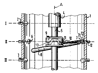
Fig. 1 is a mainly diagrammatic vertical section
through the polarity switch of this invention;
Fig. 2a is a developed view of the cam groove of Fig.
1; and
Fig. 2b is a view like Fig. 2a of a variant on the cam
groove.
Specific Description
As seen in Fig. 1 a selector drum 1 is made of an
insulating material such as glass-fiber reinforced plastic and is
centered on a vertical axis A. At an upper level I it is
provided with preselector contacts 2 (only one shown) and at a
lower level III with fine-selector contacts 3 that are engaged by
respective unillustrated terminals carried on respective shafts 4
and 5 extending along the axis A. In an intermediate level II
between the levels I and III are spring-loaded polarity contacts
6 (only one shown) that are connected to center taps of
unillustrated windings. A maltese-wheel drive or other system
used to rotate these shafts 4 about the axis A in the manner well
known in the art.
A pivot 7 is provided on a contact 12 located on the
level II and connected back to the main winding as well known per
se. A transverse bolt 7.1 on this pivot 7 defined an axis 7.2
lying in the plane II and carries a ring 8 that can rock from the
illustrated out-
4

2a~~Q~9
of-service position to an upper connecting position 6 engaging the
contacts 6 and connecting same electrically to the terminal or contact
12 so as to prevent voltage buildups in the respective windings.
A radially inwardly projecting arm 10 on the ring 8 has an
inner end provided with a roller 11 engaging in a groove 12 of a cam 9
carried on the shaft 5. This cam groove 12 has as shown in Fig. 2a a
single inflection location for the 2 x 360° rotation used in a fine
selector. The groove 9.1 has switch-on points 9.1 and switch-off
points 9.2. Thus once each revolution the ring 8 will be pivoted
upward to contact the terminals 6 briefly, thereby discharging the
respective windings. If the shaft 4 or 5 does not make a full 360°
rotation, the cam inflection can be positioned nonetheless to drain
the contacts 6 at the appropriate time during switchover.
The angles of the sides of the inflection in the cam groove
12 determine how quickly the ring 8 is pivoted up and back. In Fig.
2a the action is symmetrical. In Fig. 2b a groove 12' is shown whose
switch-on and switch-off points 9.1' and 9.2' will move the ring dif-
ferently depending on the direction of rotation of the cam 9. In such
an arrangement the ring when in the contacting position is held by the
spring contacts 6. To this end it is advantageous that the axis 7.2
is horizontally offset from the planes of the contacts 6 so that the
ring 8 lies in the contacting positions on the upper ends of the con-
tacts 6 and is held thereby. Thus to disconnect it is first necessary
to overcome the spring force, that is to push the contacts 6 out some-
what. Alternately the arm 10 could be somewhat flexible or could have
a spring connection at one of its ends so that fixed contacts 6 could
be used and the springiness of the arm 10 would maintain the necessary
contact force with the ring 8 lying on the undersides of the contacts
6 when contacting them.
5

205029
The cam 9 is fixed to the shaft 5. The groove 12 could,
however, be cut directly into the shaft 4 or 5 the cam could be other-
wise constituted.
6

Representative Drawing
A single figure which represents the drawing illustrating the invention.
Administrative Status

2024-08-01:As part of the Next Generation Patents (NGP) transition, the Canadian Patents Database (CPD) now contains a more detailed Event History, which replicates the Event Log of our new back-office solution.

Please note that "Inactive:" events refers to events no longer in use in our new back-office solution.

For a clearer understanding of the status of the application/patent presented on this page, the site Disclaimer , as well as the definitions for Patent , Event History , Maintenance Fee  and Payment History  should be consulted.

Event History

Description Date
Time Limit for Reversal Expired 2008-12-10
Letter Sent 2007-12-10
Inactive: IPC from MCD 2006-03-11
Grant by Issuance 2002-10-29
Inactive: Cover page published 2002-10-28
Inactive: Final fee received 2002-08-15
Pre-grant 2002-08-15
Notice of Allowance is Issued 2002-02-26
Letter Sent 2002-02-26
Inactive: Approved for allowance (AFA) 2002-02-15
Amendment Received - Voluntary Amendment 2002-01-18
Inactive: S.30(2) Rules - Examiner requisition 2001-09-26
Inactive: Application prosecuted on TS as of Log entry date 1999-02-03
Letter Sent 1999-02-03
Inactive: Status info is complete as of Log entry date 1999-02-03
Request for Examination Requirements Determined Compliant 1999-01-19
All Requirements for Examination Determined Compliant 1999-01-19
Application Published (Open to Public Inspection) 1993-06-14

Abandonment History

There is no abandonment history.

Maintenance Fee

The last payment was received on 2002-10-11

Note : If the full payment has not been received on or before the date indicated, a further fee may be required which may be one of the following

  • the reinstatement fee;
  • the late payment fee; or
  • additional fee to reverse deemed expiry.

Please refer to the CIPO Patent Fees web page to see all current fee amounts.

Fee History

Fee Type Anniversary Year Due Date Paid Date
MF (application, 5th anniv.) - standard 05 1997-12-10 1997-08-19
MF (application, 6th anniv.) - standard 06 1998-12-10 1998-08-03
Request for examination - standard 1999-01-19
MF (application, 7th anniv.) - standard 07 1999-12-10 1999-09-08
MF (application, 8th anniv.) - standard 08 2000-12-11 2000-11-29
MF (application, 9th anniv.) - standard 09 2001-12-10 2001-07-03
Final fee - standard 2002-08-15
MF (application, 10th anniv.) - standard 10 2002-12-10 2002-10-11
MF (patent, 11th anniv.) - standard 2003-12-10 2003-10-22
MF (patent, 12th anniv.) - standard 2004-12-10 2004-08-11
MF (patent, 13th anniv.) - standard 2005-12-12 2005-09-16
MF (patent, 14th anniv.) - standard 2006-12-11 2006-09-22
Owners on Record

Note: Records showing the ownership history in alphabetical order.

Current Owners on Record
MASCHINENFABRIK REINHAUSEN GMBH
Past Owners on Record
HEINRICH FREYMULLER
Past Owners that do not appear in the "Owners on Record" listing will appear in other documentation within the application.
Documents

To view selected files, please enter reCAPTCHA code :


To view images, click a link in the Document Description column. To download the documents, select one or more checkboxes in the first column and then click the "Download Selected in PDF format (Zip Archive)" or the "Download Selected as Single PDF" button.

List of published and non-published patent-specific documents on the CPD .

If you have any difficulty accessing content, you can call the Client Service Centre at 1-866-997-1936 or send them an e-mail at CIPO Client Service Centre.


Document
Description 
Date
(yyyy-mm-dd) 
Number of pages   Size of Image (KB) 
Abstract 1994-03-27 1 21
Cover Page 1994-03-27 1 18
Claims 1994-03-27 2 48
Drawings 1994-03-27 2 39
Description 1994-03-27 6 202
Cover Page 2002-09-25 1 48
Description 2002-01-18 6 202
Claims 2002-01-18 2 55
Representative drawing 2002-02-15 1 16
Representative drawing 1998-10-28 1 15
Acknowledgement of Request for Examination 1999-02-03 1 177
Commissioner's Notice - Application Found Allowable 2002-02-26 1 166
Maintenance Fee Notice 2008-01-21 1 173
Correspondence 2002-08-15 2 41
Correspondence 1992-12-10 1 35
Fees 1995-03-02 1 72
Fees 1996-08-07 1 64
Fees 1994-05-19 1 54