Note: Descriptions are shown in the official language in which they were submitted.
2 ~ 2 fi
The pre~ent invention is a safety electrical system that
prevents power from being supplied to an enclosed area that may
contain explosive fumes until blowers have had an opportunity to
purge the area. More particularly the present invention is an
ignition system that prevents the engi~e of a gasoline powered boat
from being turned on until the engine blowers have operatad for a
period sufficient to purge the engine room of possibly exploslve
vapors.
~EL~TED APPLICATIO~
.
This application i5 a continuation-in-part of an appllcation
by ~the same inventor and having the same title, Serlal No.
07/~52,206 filed December 15, 1989, which in turn wa~ a
cont~n~ tion-in-part of Serial No. 07/270,537 filed Novsmber 14,
1988, now abandoned.
INTRODUCTION
U.S. Coast Guard regulations require all gasoline powered
boats that have enclosed engine spaces to be equipped wlth exhaust
blowers to purge explos~ve gases prior to starting the engine. The
blowers are required to be operated for a full four minutes prior
to starting the engine~
~ hese exhaust blowers are installed by boat builders as
required by law. Unfortunately there has been no feasible way to
enforce the proper use of these safety device~. A report published
by the Department o~ Transportation, U.S. Coast Guard, "Boating
Statistics 1987" June, 1988 states that over the past fiYe years
~orty-~our people have been lcilled, nine hundred elghty-seven
in~ured and nearly twenty million dollars in damages have occurred
a~ a direct result of gasoline fuel exploslons and resulting fires
in gasoline en~ine powered cra~ts. For comparison the total amount
of damages over the past five years for all types of boating
accidents was approximately eighty-three million dollars. Thus,
the loss ca~sed by gasoline fuel - fire explosions was an alarminy
twenty-four peraent of all losses.
-2-
I
`'~
2 ~ ~ e ~ 6
The above statistics are based on reports received by the U~Sa
Coast Guard who estimate that these amount to only five to ten
percent of all reportable accldents not involving fatali~ies.
Also, these statistics are only for those jurisdictions that have
a federally approved boat numbering system.
There ha~ been a desideratum therefore for an ignltion sy~tem
or method that would compel a gasoline powered boat operator to
operate ~he blowers for an adequate period of time prior to enyine
start up, which system none-the-less must be acceptable to the
operator and not unduly frustrating or complicated. The present
invention is directed to this need.
T~IS _~VE~TION
The present invention is an electronic lnterlock or device
designed specifically to prevent fuel explosions and fire caused
by a build-up of explosive fume~ in enclosed compartment~ such as
battery rooms, paint rooms, areas that may contain natural or
propane gas ~umes and the engine rooms and auxiliary space~ Of
power boats. It may be used in any other confined area on land or
sea which should be purged oE explosive vapors prior to starting
an eng~ne or otherwise supplyin~ electrical power thereto.
The present system is designed to automatically bypass the
ignition system of an engine and simultaneously power and operate
the exhaust blower until it is safe to start the engine. Generally
speaking in the case o~ boats the blowers will automatically
operate for a predetermined period of time; e.g., full four
minutes, while preventing the ~low of cuxrent to the starter motor
thus eliminating any possibility of a spark igniting any explosive
vapors. After this predetermined period of time, the electronlc
in~erlock system ~top5 the blower and allows the operator to start
the engine. If after the predetermined perlod o~ time the operator
does not start the engine and after a period attempts to do ~o the
present system will again run the exhaust blower for another
predetermined amount of time to assure purglng of the englne space
before allowing engine start up. Thls cycle wlll automatically be
repeated so long as the ignition switch is in the "on" position~
2 ~ r~
In addition to insure safety after the boat has been started
and during the time that it is in operation, the blowers will be
automatically turned on to purge the confined areas for a
predetermined period of time on a regular ba~is. This is
especially important whan trolling or running at reduced ~peeds to
assure sufficient air flow to the engine room spaces.
To accommodate instances of extreme emergency where the boat
must be started immediately to avoid certain di~aster an emergency
bypass switch is provided that will allow the boat enqine to be
started immedia~ely while still running the exhaust blowers. To
use the bypass the operator must purposely turn the ignition swltch
to the start position with one hand and activate the bypass switch
with the other simultaneously~
The sa~ety interlock ignition sy~tem of this invention
provides maximum safety for the boat operator, passengers, marine
facillties and other boat-~. It is "boater friendly" with sensible
features that include a cold start, warm start, hot ~tart,
automatic blower cycling and an emergency bypass systemO
When the ignition switch is turned to the "off" position the
~ystem automatically powers itself down.
The exhaust blowers may still be operated at any time by a
manual switch on the dash board. Stati~tics have shown however
that operators do not run the exhaust blowers for the proper amount
of time to suf~iciently purge the conflned spaces of explosive
gases or forget to run the blowers at all prior to ~tart~ng the
engine. An operator only has to forget once when there are
explosive fumes present to cau~e considerable damage and possible
death. It should be noted that boat operators are not requlred by
law to take any type of test of boating knowledge or safety
requirementR prior to being allowed to operate a pleasure boat of
any sizell
--4--
In brief compass the present invention is a safety interlock
system for a gasoline powered boat having a gasoline engine within
an engine room and the engine room being equipped wlth a blower to
purge fumes. The blower is equipped with a blower switch and the
gasoline engine is equipped with a customary ignitlon system
including an ignition switch, a starter switch and a power ~upply
connected to the blower swltch and ignition switch.
The safe~y interlook ~ystem of this invention comprises a cold
timer switch and an ignition interlockO The cold timer switch is
operatively connected to the ignition relay switch and blower
switch. The ignition interlock is interposed between the ~tarter
~witch and the ignition switch. In operation when the startex
switch is turned "on", lt energizes the cold tlmer swltch which in
turn energizes (1) the blower switch for a first predetermlned time
period and ~2) the ignition interlock preventing energization o~
the ignition s~itch. After the first predetermined period of time
ha~ passed the cold timer switch cease~ the energization of the
blower switch and releases the ignitlon interlock permitting the
ignltion to be energized and power to go to the engine ignition
system and starter.
I It is preferred in addition to include a warm/hot time switch
aonneated to the starter switch and the ignition interlock such
that when the starter is turned on after the engine has operated
~or a time, the warm/hot time swltah observes the time since shut
down and iP longer than a second predetermined time it first turns
on the blowers while preventing an engine start up untll a
su~1cient time has passed to assure purging of the engine
compartment. Generally ~peaking the time the blowers are kept on
is proportional to the time period the enylne was not running.
-5-
~`
`~ ) 2 ~
For emergency situations the system pxeferably ha~ a bypass
switch connected to the ignition interlock. It ls phy~ically
posltioned to require the operator to operate the ~ypass switch
with one hand whlle operating the lgnitlon switch with the other
such that when both are in the "on" position the ignition can be
energized and the engine started in emergencies such as the boat
drl~ting into shallow waters. The system of ~hls invention is
designed to fail "open" so that if the bypass must be used a
conscious decision must be made which hope~ully will make the
operator think to first operate the blowers to purg the engine
room.
Also as an additional feature the interlock system of this
invention has an operatlng time that cyclically turn~ the blower
on for short periods periodically to assure that the engine room
remains ~ree of explosive fumes. This is done automatically which
frees the operator from the need to consider whether or not the
blowers should be turned on.
--6--
::., . .,.. - . . .. :. .
; r~
DRA~INGS
In the drawlngs:
FigO 1 is a schematic illustratlon of an analog si~fety
ignition system according to thi~ in~ention,
Fig. 2 is a detailed wirinq diagram broken down for reason of
clarity into four schematics, Figs. 2A, 2B, 2C and 2D,
Fig. 3 is a self explanatory contact layout of the Fig. 2
diagram, and
Fig. 4 is a digital safety ignition system according to this
invention and which includes iome additional i~atures not shown in
the ~ystem of Fig. 1.
-7
.. , . , .. , . . . . . .. .. ~ ~ . . ... . . . .
r~ -
DESCRIPTION
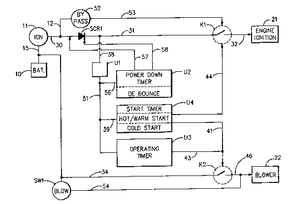
Referring to Fig. 1, illustrated is a boat ignition system.
This comprises a 12 volt source of power, battery 10, whlch by line
15 connects to lgnition switch 11 which by line 30 supplles power
to a silicon controlled rectifier SCR 1. SC~ 1 connect~ by llne
31 to ignition relay K1~ Lines 33 and 34 supply power to blower
relay switch K2. Power is also directly ~upplied by line 33 to
blower switch SW1 and thence by lines 54 and 46 ~o a blower 22.
Thus, the blower can be operated in the usual manner lndependently
of the present ignition safety system.
SCR 1 is connected by lines 31 and 38 to regulatsr U1 which
reduces the voltage from 12 to 5 volts. Regulator U1 is connected
by lines 51 and 39 to a start timer U4 and by line 51 to op~rating
timer U3.
Switch 11 connects by line 30 and 1~ in series to bypass
switch 52 on the instrument panel. Line 53 connect~ the bypass
switch to relay K1.
In accordance with this invention timer U4 is connected by
line 44 to relay K1. The relay ~w~tch K1 will not close unless
activated by timer U4 or by bypass switch 52.
The engine lgnition system is indicated at 21 and the blower
or blowers are indicated at 22.
In operation when ignition switch 11 i~ turned on and xelay
swit~h K1 i~ ln the open posltion, power lows via llne 38
regulator U1 and lines 51 and 40 to the start timer U4. The timer
i~ a count up/down timer. If the engine has not been operating~
i~e~, for a cold ~tart, the timer by line 41 activate~ the blower
relay ~2 so that the blower relay can pass power by line 46 to
blower 22 to cause it to operate. The cold timer count~ down for
a predetermined time period and after that time period shuts down
the blower 22 and activates by line 44 the ignition relay K1 such
that 12 volt power can flow via lines 30, 31 and 32 to the engine
ignition 21 starting the engine~
-8-
.. ~ . ... .. .. . ... . . . . .. .
... . . . . . . ... .
;i 2 ~
In a~ emergency the operator by turning both ignition switch
11 and bypass switch 52 on simultaneously can pass by line 53
energizing current to the ignition relay K1 which permlts direct
starting of the engine~ Also, prlor to start up or at any other
time, the operator by turning blower switch S~1 on can pass current
directly to the blower 22 by line 54.
After the engine has been operating for a time and shut down
it may not be necessary to purge the engine compartment for a
predetermined time period prlor to start up. When the ~ngine is
shut off timer U4 commences counting down for i3ay, a period of
twenty minutes. If the engine is attempted to be turned on agal~
withln that time at the time of englne shut off the timer commences
counting how long the engine has been shut off. If it has been
shut off for more than one minute, for example, timer U4 is set to
prevent the engine start up by not energi2ing K1 while turning the
blowers relay on by line 41 for a ~lme perlod of say two minutes
to lnsure purging of the engine compartment. ~hereafter the timer
~hut~ of~ the blower and activates the ignition i~terlock allowing
engine ignition.
Experience has shown that it is advisable to operate the
blowers periodically in an operating vessel to assure that the
englne room is purged of any explosive vapor~ especially while
operating at low speeds or down wind where there may be very little
ventilation. ~o this end the present system includeis an operating
timer U3, which when the ignition switch is on is activated by
power from line 5~l and automatically turns the blower on, for
example, one minute out of each twenty by activating the blower
r~lay via lines 43 and 46. The blower i~ kept cycling while the
engine is operating~
! ,' I; .:
- -
When ignition 11 is turned off it is necessary to keep power
to the system to allow timer U4 to operate so that start up will
be permitted within, for example, a twenty minute period with less
than a four minute delay for blower operation. To this end a power
down timer U2 is inserted into the circuit~ It is connectPd to
regulator U1 by lines 51 and 56. Timer U2 is an up only counter
and counts how long switch 11 has been in the off position. When
the switch has been in the off position for say, a period of twenty
continuous minutes, timer U2 and its related component~ by line 57
pulls the anode of SCR 1 to ground while a +12 volt potential is
applied to the ca~hode by line 58. This reverse polarity turn~
SCR1 off thus turning off power to the circult. If switch 11 is
turned on the power down cycle i5 stopped instantly ~via Q2 - ~ee
~ig. 2).
The power down timer U2 will only power the circuit down when
the ign~tion switch has been in the off position for the twenty
continuous minutes. Any time switch 11 is turned on timer U2 is
zeroed (the charge on C5, see Fig. 2, is dumped) and the full
twenty minutes in the off position is again needed ~or a power
draln to occur.
With reference to Fig~ 2, the components identified thereon
are described in the followlng listing. The ~ame designations are
u~ed in Figs~ 1 and 2 for the following components: SCR1, U2, U3,
U4, K1, K2 and SW1.
When the ignition switch 11 is turned on a voltage is applied
to the gake of SC~1 allowing it to conduct power to the clrcuit.
When power is first applied to the circuit the output of the cold
start circuit V4 second stage will be high. Thi~ will enable the
blower and the blower light B2 by energizing coil K2 thus clo~ing
the contacts K2. The circuit will also light the inhibit light B4
as well as inhibiting the ignition. The timer U4 commences to
start to count up by an increasing charge on C14. When the timer
U4 has reached its terminal count, for example, four minutes, the
blower ~2 and the inhiblt light will shut off. The aircuit will
then enable ignition by energizing coll K1 thus closlng the
contacts o~ K1.
--1 0--
;,
' ~3
The start timer U4 is a chip acting as an up/down timer. This
timer counts up when ignition switch is on and down when lgnition
switch is off. This means that if t~e circuit is powered up and
the ignition switch is left in the on position for say three
minut~s then turned to the off position for say one minute and
turned back to the on position the circuit has counted up three
minutes and down one minute thus leaving two more minutes necessary
in the on po~ition to reach the four minute power time. ~-
For a hot/warm start the timer U4 counts how lony the ~gnition
switch has not been in the on posltion. If an ignltion ls tried
after the switch has not been in the on po~ition for greater than
one minute, for example, the inhibit light is llt ignition ls
inhibited and the blower operated until the inhibit timer U4 has
counted down with the ignition switch in the on position for the
predetermined amount of time. This can be set depending on how
long the starter switch has been off. Af~er this predetermined
time the inhlbit light will then turn off and ignition will be
enabled by energizing X1.
U4 is set however such that i~ the ignition has been o~f for
less than one minute immediate energizing of K1 will take place
and immediate start up will thus be allowed.
After the blowers have gone through their initial cold start
cycle timer U3 will then cause the blowers to cycle, for example,
~or one minute out of every twenty minuteæ by energizing R2. Since
the blower light B2 is wired in parallel with the blowers any time
the blowers are on the blower llght will also be lit.
It should be noted that the circuit will not cause the blowers
to cycle unless the starter switch is in the on position. Once the
start cycle has been completed and the key is in the on position
the blowers will cycle ~or one minute every twenty minutes via
tlmer U3.
Power down timer U2/ second stage, i8 an up only counter~
This counter counts how long tha ignition switch ha~ been in tha
accessory off posltionO When the lgnitl~n switch has been in the
off position for say, twenty continuous minutes the timer will turn
off Q3 which will turn on Q1 which enables current to flow through
Q2 (normally on). This will pull the anode of SCR1 to ground while
C1 will provide 12 volts to the cathode. This rever~e polarity
will turn the SCR1 off thus turning off power to the clrcuit. If
the ignition switch is turned to the on position the lnsta~t the
current is being powered down Q2 will turn off ~topping the power
down cycle.
-The power down timer U2 will only power the cycle down when
the ignition switch has been in the off position for the twenty
continuous minutes. ~ny time the ignition ~witch l~ turned to the
on position the power down timer is zeroed, i.e., the charge on C5
is dumped and a full twenty minutes in the off position is again
needed for a power down to occur.
An up/down timer U2, stage one, is used to debounce the ~ignal
from the ignition switch when the signal changes state (ON - OFF,
OPF - ON). It must remain in that state for at lea~t say, 0.5
seconds befoxe the debounce circuitry will acknowledge it is a
valid change o~ state.
If the operator turns on blower overrid~ switch SW1 the
blower~ will turn on and the blower light B2 wlll light. ~his will
happen regardle~s of the state o~ the circuit or the position of
the ignition switch.
IE the operator turns on the ignition override switch 52 all
inhibit clrcuitry is bypassed and the starter may be activated by
turning the ignition switch to the on position~ The override
switch is a momentary switch that must be held in the on position.
All times given in the above description are exemplar only and
can be adjusted a~ need be to fit an desired operating paxamet~rs.
As an additional inventive feature, it is believed that the
use o a timing chip (integrated circuit) in con~unction with the
logic chip to ef~ect retentive/non retentive up/down timing and to
avold race conditions is novel.
-12-
In summary', 3~ gasoline engine powered boat sa~ety ignition
analog system illustrated in Figsc 1 - 3 d~ R
Cold Start Locks out all current flow to the
ignition system while powering the
exhau~t blowers for a
predetermined period; e~g., four
minutes,
Warm Start Blocks out all current flow to the
lgnition system after the lgnition
system has been off for more than one
minute and up to twenty minutesiwhile
powering the exhaust blowers for a
predetermined period~
.
Hot Start Allows ignition to start immediately
for up to, for example, one mlnute
every twenty.
Emergency Bypass Allows the operator to bypass the
interlock system in cases o~ dire
emergencies such as imminent
collision or grounding while still
operating the exhaust blowers.
-13-
2~52~
Turning now to the digital system of Fig~ 4, illustrated is
a boat ignition system. Thls comprises a 12 volt source of power
battery 123 which by line 100 connects to ignition switches 125
and 126 which by lines 103 and 105 supplies power to electronically
controlled ignition safety switches 131 and 132. Power is also
supplied via line 118 to manual blower switch 143, via llne 117 to
the electronically controlled blower switch 136, to the accessory
switch 124 and to the electronically controlled sensor power switch
142 through line 100~ Switch 142 supplies power through~line 110
to gas sensors 140 and 141.
Ignition switches 125 and 126 connect by lines 103 and 105 to
bypass (or override) switch 127 that :Ls operated manually. Lines
102 and 104 connect the override switch 127 directly to starter
motors 133 and 134 bypassing ignition safety switches 131 and 132.
In accordance with thiis invention sequencer 129 is connected
by lines 107 and 108 to switches 131 and 132. Sequencer 129 is
based on a software programmed microprocessor chip to have the
functions shown in Fig. 4 and such others as may be desired. The
electronically controlled switches 131 and 132 will not close
unless activated by the sequencer 129. The sequencer 129 is also
connected by line 116 to switch 142. The electronically controlled
switch 142 will not close unless actlvated by the sequencer 129.
~he sequencer 129 ii~ connected by line 109 to the electronically
controlled blower switch 136. The blower or blowers 138 cannot be
operated unless activated b~ the manual blower switch 143 or the
electronically controlled blower switch 136.
- - 2 ~ ~ ~ii .P? 2 ~
The sequencer 129 is powered directly from the battery by line
1n1 and is in operation continuously. When the accessory switch
124 is turned on line 106 sign~l~ ~ sequencer. The sequencer 129
first performs a self test~ ~ i notifies the display unit 130 of the
results of this test. The sequencer 129 then ac~ivates by line 116
the sensor power switch 142 supplying power to the sensors 14C and
141 by llne 110. If the engine has not been operating, i.eO, for
a cold start, the sequencer by line 109 activates the blower switch
~ 36 so that the blower switch 136 can pass power by l~ne 115 ko
blower 138 to cause it to operate. The cold start timer within the
sequencer 129 counts down for a predetermined time and after that
time period shuts down blower 138. The sequencer 129 then reads
the sensors 140 and 141 by lines 121 and 122 to detect the presence
of dangerous gases. If there are no dangerous gases detected the
sequencer turns on the blowers 138 by line 109 for a predetermined
period of time and then activates by lines 107 and 108 the ignltion
safety switches 131 and 132 such that when the ignition switches
125 and 126 are manually activated power can flow by lines 103,
105, 113 and 11~ to the engine starter motors 133 and 134. The
sequencer 129 then enters a normal mode of operation during which
the sensors are read at predetermined time intervals.
I~ the se~uencer 129 by lines 121 and 122 from the sensors 140
and 141 detects the presence of dangerous gase~ before activation
o~ the ignition sa~ety switches 131 and 132 then the blower switch
36 remains activated and a warning message is displayed on the
seqllencer 129 display unit 130. While dangerou~ gases are detected
the ignikion safety switches 131 and 132 will remain disabled. The
sequencer 129 will continue to periodically monitor the sensors 140
and 141 by lines 121 and 122. The warning message will be
played and the blowers 138 will remain on until the sequencer
129 detects the absence of such dangerous gases. At such time the
sequencer 129 will activate the ignition safety switches 131 and
132 by llnes 107 and 108.
-15-
~,
;ji
~`- 2~3~
If the sequencer 129 by lines 121 and 122 from the sensors 140
and 141 detects the presence of dangerous gases after entry into
the normal mode of operation the ignition safety switches 131 and
132 will be deactivated ~y lines 107 and 108 and the blower switch
136 will be activated by line 109 turning on the blowers 138. The
sequencer will send by line 112 a warning message to the display
unit 130 and continue to periodically monitor the sensors 140 and
141 by lines 121 and 122. The warning message will be displayed
and the blowers 138 wi]l remain on until the sequencer 129 detects
the absence of such dangerous gases. At such time the sequencer
129 will activate the ignition ~afety sw~tche~ 131 and 132 by lines
107 and 108.
If the sequencer 129 by lines 1~1 and 122 from the sensors 140
and 141 detects a missing or malfunctioning sensor 140 or 141 then
a warning is displayed by line 112 on the display unit 130 and an
audible alarm 145 is activated by line 144. Additionally, the
sequencer 129 ~ill deactivate the ignition safety switches 131 and
132 thereby not allowing the manual lgnition switches 125 and 126
to operate unless the manual bypass switch 127 is operated at the
same time.
In an emergency, the operator by turning both the ignition
switches 125 and 126 and the bypass swltch 127 on simultaneously
can pass by lines 102 and 104 current to the starter motors 133
and 134 thereby directly starting the enginesO Also, before start
up or at any other time, the operator by turning blower switch 143
on can pass current directly to the blowers 138 by line 118.
After the engine has been operating for a time and shut down
it may not be necessary to purge the engine compartment for the
full predetermined period of time before staxt up~ When the engine
is shut off a timer within the sequencer 129 begins counting down
irom a calculated starting point. When the engine i9 again started
a calculation is made wlthin the sequencer 129 to determine the
start up safety hold period. If a short period of time has passed
the safety period duration is lessened and this is termed a warm
s~art. If a very short period of time has elapsed between shut
down and start up then immediate ~tart up may be allowed and this
is termed a hot start.
-16-
3~S~3
Experience has shown that it is advisable to operate the
blowers periodically in an operating vessel to assure that the
engine room is purged of any explosive vapors especially while
operating at low speeds or down wind where there may be very little
ventilation. To this end the present system i~cludes an operating
timer within the sequencer 1~9 which when the acces30ry switch 124
is active automatically turns the blower~ 138 through blower switch
136 by line 109 on periodically for predetermined perlods of time.
The blower is kept cycling in thi~ manner while the e~gine is
operating.
~ he display and control unit 130 displays all warning ~nd
danger messages. When the safety period is in effect the display
unit shows the time rsmaining in minutes and seconds. When the
~equencer 129 is in normal operating mode and there are no safety
periods or warnings in effect the display unit 130 displays the
time of day. When the sequencer 12~ is in standby mode with the
accessory switch 124 inactive the display 130 will conserve battery
power by not displaying any informat~on.
When the sequéncer 129 is in standby mode by the accessory
switch 124 being inactive the sequencer 129 may be put into sleep
mode by activating the controls on the display and control unit
130. While in sleep mode the sequencer 129 will periodically apply
power to the sensors 140 and 141 through the sensor power switch
142 by line 116. After the sensors 140 and 141 have stabilized the
sequencer 129 will detect dangerous gas that may be present. If
dangerous gas has been detected the sequencer will sound the
audible alarm 145 by line 144 and display a visual warning message
at the display unit 130 by llne 112 and activate the blower switch
136 by line 109 to exhaust the gas. If no dangerous gas has been
detected the sequencer 129 will deactivate the sensor power switch
142 by llne 116 and resume sleep mode until the next periodic gas
check.
The display and control unit 130 will additionally have a
switch ~or setting the tlme of day and two vl~ual lndicator~, one
to indicate blowers active and the other to indicate an ignition
sa~ety swltch inactive state~
-17-
,3 ~ ~
There will optionally be a remote display and control unit 135
that will have the two visual indicators and an audible alarm
connected to sequencer 129 by line 111 identical to those in the
display and control unit 130 and a bypas switch functionally
identical to 127.
Throughout its operating modes sequencer 129 maintains a
record of its current state in non volatile memory 138 connected
to the sequencer by line 137. For examp~e/ if the bypass switch
127 is used the sequencer will be informed by line 119. If a gas
explosion should result from bypass switch 127 being used while
dangerous gas was present this action would be recorded in the non
volatile memory 1390
-18-
i~,
;l