Note: Descriptions are shown in the official language in which they were submitted.
208B035
I
SMALL-DIAMETER SUPEREI.ASTIC WIRE GUIDÆ
BACKGROUND OF THE INVENTION
This invention relates general1y to a wire guide used to
position a catheter or other medical tool at a precise
location within a patient. In particular, tl1is invention
relates to a slnall-diameter wire guide which can ~e steere~
into and along very narrow blood vessels to locate its disl;al
end ln a preclse posltlon.
In order to negotiate a tortuous path or avoid obstac].es
during an insertion, wire yuides freqllently include a floppy
tip that is often biased iII a certain direction. However, it
is desirable that the remainillg portion o the wi.re yuide be
-somewhat elastic and resistant ~o kinking but still able to
transmit a torque so that the physician can reliabl.y charlge
t~le direction of the bias tip to make a turn or avoi~ an
obstac1e while advancing the wire yuide illtO posi.ti.on. It
has been foulld that using a superelastic material (sometillles
expressed as "pseudoelastic"), such as a nickel titaniw
a].loy, in the body of the wire guide has si.gnifi.cant
advantages over collventional steel wire guides, in that
nitinol's superelastic propeLties call allow physicians to
reach mucll more remote locations wi.thin the body. In ot..her
words, wire guides made of certain nickel titaniwll alloys
simply llave improved torque control and more resistance ~o
kinking tllan conventiona1 stainless steei.
What is needed is an extremely sma11-diameter ~ire guide
which has improved torque control over conventional stainless
steel wire guides, has substantial kink-resistance over the
majority of its length, has a distal region of
gradual~ creasi.ng flexibili.ty alld includes an extremely
flexib].e radiopaque distal coil tip.
20860~!j
SUMMARY OF THE INVRNTION
A small diameter wire guide according to one embodiment
of the present invention comprises a m~ndrel of metallic
superelastic material having a length, an elongated proximal
section and a distal region. Tlle superelastic material
completes its transformation to austenite at a temperature of
about 14C. The proximal section has a uniform diameter ]ess
than 0.020 inches. The distal region of the mandrel has
serially disposed a first linear tapered portion, a first
reduced diameter portion, a second linear tapered portion and
a second reduced-diameter portion. The first tapered portion
is adjacent the distal end o~ the proximal section. A coil
having an outer diameter less than 0.020 inches is attached
to tlle distal region and coaxially surrounds the first and
second reduced diameter portions as wel] and the second
tapered portion of the distal region. Finally, a smoot~ly
rounded tip is attached to the secolld reduced diameter
portion and shields the distal end of tlle coil.
In another embodiment of the present invention, there is
provided a small diameter wire guide that comprises a mandrel
of metallic superelastic material llaving a length, an
elongated proximal section and a distal region. The
superelastic material completes its transformatioll to
austenite at a temperature of about 14C. The proximal
section has a uniform diameter less than 0.020 inches. The
distal region of t-lle mandrel has serially disposed a first
linear tapered portion, a first reduced diameter portion, a
second linear tapered port;on, a secon~ recluced-diameter
portion, a third linear tapered portion arld a third reduced
diameter portion. The first tapered portion is adjacent tlle
-distal end-of the proximal section. A coil having an outer
diameter less than 0.020 inches is attached to the distal
region and coaxially surroullds the second and third reduced
diameter portions and the third linear tapered portion.
2086n3~
Finally, a smoothly rounded tip is attached to the second
reduced diameter portion and shields the distal end of the
coil.
One object of the present invention is to provide an
improved small-diameter wire guide.
Related objects and advantages of the present invention
will be apparent from the following description.
20~6035
BRIEF DESCRIE'TIC)N (~F TE~E DRAWINGS
FIG . 1 is a f ragmentary longitudinal sectional view of a
small-diameter wire guide according to one ernbodirnent of the
presellt invent i on .
FIG. 2 is a fragrllentary longitudinal sectional view of a
small-diameter wire guide according to anottler embodi ment of
the present invent ion .
208603t~
DESCRIPTION OF THE PREFERRED E~BODIMENT
For the purposes of promoting an understanding of t~le
principles of the invention, reference will now be made to
tlle embodiment illustrated in the drawings and speci~ic
language will be used to describe the same. It will
nevertheless be understood that no limitation of the scope o~
the invention is thereby in~ended, such alterations and
further modifications in the illustrated device, and suc~l
further applications of the principles of the invention as
illustrated therein being contemplated as would normally
occur to one skilled in the art to which the i1lvention
relates.
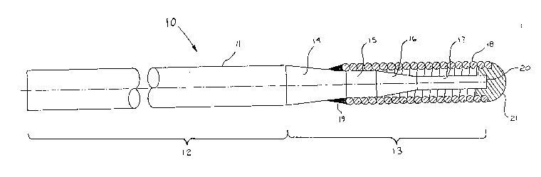
Referring now to FIG. 1, there is shown a wire guide l0
according to one embodiment o the preserlt invention. Wire
guide l0 includes a mandrel ll which is fornled from a
metallic superelastic material such as nitinol, a nickel
titanium alloy. Mandrel 11 is preferably formed from an
alloy having 42-50% titanium and 50-58% nickel by weight.
Iron and/or chromium, up to 3 % by weigh~, can be added to
the nitinol to increase strenyth. The mandrel material
preferably completes its transformation to austenite at a
- temperature of about ]4C, which is believed to result in
yreater ~lexibility than a mandril with a lower
trans~ormation temperature without sacrificirlg torque
transmission per~ormance.
Mandrel ll is divided into elongated proximal sectioll 12
and distal region 13. Elongated proximal section 12 has a
uniform diameter less than 0.020 inches, and prefera~ly a
diameter of 0.014 or 0.018 inches. The relatively short
distal region 13 of mandrel 11 is made up of a first linear
tapered porti~n 14, a first reduced diameter portion 15, a
second linear tapered portioll 16 and a second reduced
diameter portion 17. First tapered portion 1~ defines the
end of proximal section -12 and the beginrlin~ of the distal
2086035
--6--
region 13. Finally, wire guide 10 includes a coil 18
attached to the distal region and coaxially surrounding
substantially all but the first tapered portion of t;lle distal
reglon.
Coil 18 is sllown attached by weld 19 at a point where tlle
diameter of the first tapered portion 14 eqllals l:he insi~e
diameter of the coil. Coil 18, which is preferably formed of
a radiopaque platinum-tungsten alloy wire (92% platinum and
8% tungsten) can be bonded to first tapered portion 14 and/or
first reduced diamet-er portion 15 by some conventional means
such~as gluing , soldering, welding or possibly by a crimping
process. Coil 18 coaxially surrounds most of the d-i6tal
region of the wire guide and extends a slight distance beyond
the distal tip 20 of mandrel 11. Coil 18 could also be made
from stainless steel, nitinol or another bio-compatible
alloy. A smoothly rounded tip-21 is atta~hed to coil ]8 and
second reduced diameter portion 17 in order to shield t~le
distal e~d of the coil during the insertioll procedure . Tip
21 can be either a weld or solder. Wire guide 10 can also be
coated with at least one polymer layer in order to increase
lubricity. One coating could be a hydrophilic and would
cover coil 18 and a majority of mandrel 11, leaving the
extreme proximal portion of the mandrel uncoated so that the
physician can more easily grasp the wire guide.
E`irst linear tapered portion 14 defines a redllction in
- diameter of at least 40% from that o~ the elongated proximal
section 12. This particular construction allows for greater
tip flexibility and easier entry into distal vessels of a
patiellt while stil] retaining the ability to suppo~t a
balloon or other catheter. Reduced diameter portiorl 15 is
relatively short, having a length less than 2 cm. llle
diameter of portion 15 can be made substantially equal to ~he
inner diameter o~ radiopaque coil 18. Second linear tapered
portion 16 defines at least a Z5% reduction in diameter from
2U86035
portion 15 to portion 17 at the distal end of nlandLel 11.
Wire guides according to this eMbodiment of the present
invention have a length in the range 60-320 cm and preferably
have a mandrel length on tlle order of 185 cm. On]y 10 crn of
~his length is made up of the distal region and the renlailling
175 cm is made up of the uni~orm diameter proximal section
12. Again, proximal section 12 preferably has a diameter of
0.014 or 0.018 inch diameter nitinol wixe. First linear
tapered portion 14 is preferal)ly approximately 3 cm in length
and defines a reduction in diameter down to approximate]y
0.0065 inches for first reduced-diameter portion 15. Portion
15 is preferably approximately 1.5 cm in length. ~econd
linear taper portion 16 is preferably about 2 cm ill lenyt~
and defines a reduction in diameter down to approximately
0.0035 inch for second reduced-diameter portion 17, which is
preferably approxilnately 3.5 cm in lenyth. Based upon t~lese
dimensions, radiopaque coil 18 will preferably be just over 7
cm in lengtll. One variation of this embodimellt contemplates
a 0.018 inc~l diameter mandril and a coil having an outer
diameter of 0.014 inch. Ot~lerwise, the outer-diameter of the
coil is generally preferred to be ]e.ss than or equal to the
diameter of proximal section 12.
Referring now to FIG. 2, t~lere is shown a wire guide 30
according to another embodiment of the present invention.
Wire guide 30, like wire guide 10 discussed earlier, includes
a mandrel 31 formed of a metallic superelastic material, such
as a nickel titaniulll alloy whic:ll completes its trans~ormation
to austenite at a temperature of about 14C. Mandrel 31
consists of an elongated proxilllal section 32 and a distal
region 33. Distal region 33 is made up of first linear
tapered portion 34, first reduced-diameter portion 35, second
linear tapered portiorl 36, second reduced-diameter portion
37, a third linear tapered portion 38 and finally a thild
reduced-diameter portio~l 39 at ~IIe distal tip of mandrel 31.
35 A coil 40, preferably formed rom a radiopaque platinum ~-
20~603~
--8--
alloy, is attached with weld 41 to the distal region where
the inside diameter of the coil equals that of the mandrel.
Coil 40 coaxially su~rourlds reduced-diameter portion 37,
linear tapered portion 38 and reduced-diameter portion 39. A
smoothly rounded tip 43 is at~ached to coil 40 and third
reduced diameter portion 39 in order to keep tlle coil secured
to the mandrel and to shield the distal end of the coil
during the insert-ion procedure. This enlbodiment of ~he
invention i.s particularly well suited for the perEormance of
PTCA. Wire guide 30 has a soEt flexible tip, a stiff
proximal sha~t, and an area o~ transition that woul~ be more
supportive of a balloon catheter while still being flexible
enough to track distal vessels.
The outer diameter of coil 40 is less than or equal to
the diameter of elongated proximal section 32. Elongated
proximal section 32 is less than 0.020 inclles in diameter and
preferably i.s formed from 0.014 or 0.018 inch diameter
rlitinol wire. Coil 40 is relatively short, normally makirlg
up less thall 10% of the overall length of rnandrel 31. The
majority, or over 70% of the length of the distal region, is
made up of the first, second and tllird reduced-diameter
portions. In other wordsj t~le first second and third linear
tapered portions are relatively short in length and define
relatively sharp transitions in diameter. The first, second
and third tapered portions preferably have lengths that a-re
substantially eqllal. Like the embodiment described earlier,
coil 40 is attached in a conventional manner to tlle distal
region 33.
The mandrel for this embodlment of the present invention
can range in length from 60 to 320 cm but preferably has a
lengtll on the order oE 180 cm. Of this lenyth, only the
distal 27 cm make up tlle distal region portion of mandrel
31. Each of the linear tapered regions are preferably on the
order of 2 cm in length and define relatively a~rupt changes
in the marldril's diameter. First reduced-dialneter portion 35
~ 208~35
is preferably about 10 cm in length and defines a diameter on
the order of 0.010 inches. Second reduced-diameter portion
37 preferably has a length on the order of 5 cm and defines a
diameter Oll the order of 0.0070 inches. lhird
reduced-diameter portion 39 at the distal tip of the mandlel
is preferably about 6 cm in lenyth. Based upon these example
dimensions, radiopaque platinurn coil 40 would preferably be
on the order of 13 cm in length and would extend just beyond
the distal tip 42 of reduced-diameter section 39. Coil 40 is
generally preferred to have an outer diameter less tllan or
equal to the diarneter-of proxirnal section 32. In one
specific embodiment, coil 40 has an ou-ter diamet:er of O.OJ4
inch and proximal section 32 has a diameter of 0.018 inch.
It is important to note that wire guides having more than
three tapered and reduce-d diarneter portions are within the
intended scope of tllis invention. Depending upon the
intended application for the wire guide, the distal region
could include four or more alternating tapered ancl reduced
diameter portions in the distal region of the mandrel.
Furthermore, the lengths of each tapered portion or reduced
- diameter portion could also be varied from the exam~les
described above without departing ~rom the intende~l scope of
the invention. Finally, tlle change in diameter of the
mandrel defined by each tapered pol~ion could be varied
solnewhat from the examples described above. It has been
found that- manuf-acturing wire guides having a plurali~y of
al~ernating tapers and reduced diameter portions is muctl more
reliably and easily acconlplished tharl alternative]y
manufactllritlg a sinyle elotlgated tapel- in lhe distal region
of the mandrel.
While the invention has been illustrated and described in
detail in the drawings and foreyoing description, the same is
to be considered as illustrative and not restrictive in
character, it being understood that only the preferred
embodilnent has been shown and described and that all changes
and modifications that come within the spirit of the
invention are desired to be protected.