Note: Descriptions are shown in the official language in which they were submitted.
WO 92/lg34~ r~r/U~1/0288~
~E~
Qil~all~m
Back~round Qf Ih~ v~n~ion
Thi~ invent on relat~ ~ an ~r ~par~n syst0m and mora
parti~larly to a mul~i-ph~ ~par~n pro~s, a comrrK~n u~ for which is
found in nil field drillin~, proJu~, ~N~ nfinin~ oper~ion3, to enhanc0 ths
~r~vity sep~ratlon of immiscibb liqu~d~ by pr~i~ ~r~on ~ a fluid
susp~n ~uch a~ ~ h~ a ~ ~mp~ ac~ ~ an ernulsion
stabilker or oil ~at~ ~llc~ ~ neu~ral b~yancy.
A v~bty ol sapar~ ~ ~, ~1~ in p0~0~um inclust y
applic~ions ar0 c~emsd with an ema~lslon l~yer ~med 5n ~ typ05 of
systems whieh provide~ probbms as ~o ~1 sepa~atiors ~f t~ primarily
oil and watar com~ents ~r~f.
1~ Durin~ the producti~ ~ p~l~3m hydro~ ~re is o~ana substartial amour~t ~f watar produ~. The ~ount of w~3ter will vary
depen :lin~ ~n many facto~, ~uch as~ ~ type oF r~voir and form~tions
from which the fluW~ are producad; (~) ~ ~e ~f ttle w011 pr~ucin~ l~e fluids;
(33 the ~ype of ~han~d oil ra~ery ~ R) sy~ern ~h~t is u~ed, as for
20 example ws~er~d and steam fls~ , 1~ of whi* will Ir~e~ ~ ~rnourlt
of water produced.
As oil is produ~d it must be ~lteti from tl~ water. The ease
of this separation is affec~ed by the Fluicl pro~erties as w011~ physical and
chemical factors. Some fa~tors whidl may lead to th0 ~rmation of emul~ion
25 and thus adversely affect 5eparation ~ ou ~ water are:
1. Tight reservoirs with low ~ros~y and permeabil~ty, whsre oi~
drople~s will be sheared simply by movin~ throu~3h the reservoir as the
oil is produced;
2. The addition of chemicals sueh as may be used in chemical
floods or corrosion inhibitors used in ~he well;
.. ':' "., ', ' " , '. ~' ', ' . .' .
.. ...
WO 92/~9348 . PCI'/U~91/028Xf~ I
2Q86~2~
3. Shearin~ of fluid droplets clue to pumps or any number of devics~
which may cause hi~h turbuler~ such ~ a vatv~; and
4. Solid~ partic~s w~lic~ ervo to ~ ilke emulsi~ns as in oil
wet colloids.
Wl~n drillin~ p~trolsum r~ ~ beir~3 drilled frorn ~
undar~rour~ forma~ons can ~rve to f~m an oil w~ nucleu~ abollt which
emulsions ~ fonn.
~other situation l~adir~ to the probl~n~ ~nvoh~ w~rlcl ~ude
0 SUpplii35 ~3ettinç~ much p~rsr in quallty. AvaUabl0 ~rudes are ~ n0 i~0~rl
more sour, and dirtiar. ~avy, ~ cru~s h~ n~e par~ubte matter;
and hoW it br~er. Thi~ adv~ cha~ ~ c~b o~ ~ ~s h~Y~
si~ni~ o,~r~ ~ anJ ~rro~ion Imp icati~ ~ r0fir?ery ur~. Th~e are a
numb~r o~ oomj~nen~ whi~ may appsar in ~ude uil 8~k8 ~IWl in ve~y low
1~ quanfflie~ which can cause d~salffn~ a~ c~r~ion Gompli~on~. The~e
componer~ could include ~ particulates, oii fll31d prod~ng ch~mi~s and
production sffmlJlants. Part ~ ~ problem stems ~rom an inc7easæ in ttl3 use
of seconda~y and ~ertiary r~very m~s which bad ~o the produc~on of
lti~htly emulsified fluids from water flOOd~, ~ic fl~s, surfa~ ~ds, fire
floods and Ule ~neral use of weU s~mul~t ~m~ls.
Thus, it ~ s~n ~t a va~ty o~ oil ir~y probbms ~oaated
with drilling, producin~ and r~fining petrobum hydro~bons, all deal with
separa~in~ oil and water err ulsions. ~t is like~y ~a~ oilJw~ter separation in other
industrial environmen~ has similar problems which may ba treat0d accordingiy
~5 as described hereln. Many devic~s and methods have b~erl used ~o enhance
tha effe~tiveness o~ such oil/w~er separa~ion. Such devi~s and ma~hods may
involve ~he us~ of chemicals to facilita~0 phasa separa~n, the addi~ion of hea~
to reduce ViSCOSfty O~ fl~ids, ~e us0 ~ structured packin~, speaally
desiyned flow paths, fllter~ and other such mechanic~l devicss to stn~cture flowthat produoes contact of the com~nents in a rnixture to promota coalescence,
or th use of el0ctrostatic devices to cre~te electric fields and charg0s tha~
.
.' ~ ' '~ ' ,~ . ' ,:, , ' . ,
. , .' . ' ~
. ................................. . .. .
'' - ,. .. ..
.
,
wo 92/~9348 Pcr/lJ~sl/o2~8f~
!: 2086320
3 -
promota coalescenc0 and separation of mKture ~ornponents.
Desa~in~a
A s~ic petrol0um pro~s;s wt i~h typm~ ~h~ i~ pro~m
has to do with crude oil d~stilbt~n. Cr~ stili~ are ~e fir~ ~or proc~ssin~
5 unrts in a refinery. They are used to ~parate ~e crude oils by distillation into
fractions a~ordin~ to boilin~ poir~t. If ~he ~s~ oontert of the ~ude ~1 is s~rea~er
than 10 Ib/1,000 b~, ~he uude requir~ de~n~3 to minimke tc~lin~ ard
corr~ caused by sa!t dep~ on hea~ r~urFac~ ~nd ~ forrn~
by de~mposition of the chlorWe ~. In ~ on, some rr~tals wh~lch can0 cau~ ca talyst deacth/ation in c~ pr~in~ unit~ ~e p~lal~ rej~ed in
desal~n~ prooess.
Th~ trend toward runni~ 1~ CrUCI9 Ot~ ha~ hcroa~0d the
impor~ o7 emc~ent d~altin0 of crude. T~0 ~t in ~ ~18 In ~ form
of dissolved or susperlded ~It crys~als in wa~sr emulsiFied with the crude oil.
15 it is important to note ~h~t whlle ~e t~nn d~l~in~ i~ ~1 'to descn~ ~e
p
irnpuriffes in tha ~ude oil rn~y be ~r~l or indu~d. T~ water in c~le oil i~
u~ually in ~e fonn oF a water in oil enwsion. The emul~lon is s~abiiked by
surface active ~gent3 in the oil. Emulsion s~bDizers ~uch a8 ~phalts, re~ins,
20 waxes, solids and organie acids aW to l~ pr~lem of de~tir~ ~iern ~wie.
Impur~ties are ~en ~ized a~ ~ which ~re w~r soluble
and are remwable by washin0 and ~ which are water insoiuble and nc~t
readily removabb by washin~. The oi! insol~Jble impurities are ~ornetim0s
refarred to as ~he oleophQbic or oii-hating impurities. These include water, sal~,
25. and some solids.
P~non~ th0 more common irnpurities found in çrud0 oil are si!t,
sand, iron oxide, iron sul~ide, arsenio and stron~ium, sedirren~s, the chloridesof sodium, potassium, ~iaum and ma~nesium; the sutFates of potassium,
magnesium, calcium and ~odium; crystalline ~alt, carbon, sul~r, salts and
30 water.
In addition to the na~urally occurring impurities in orude oils, there
.. . . .
......................... .- ' :
.
,-.: .. ' .' '.' ~ ' '
,
WO 92/19348 PCr/US91/02B86
- 20~320 4
are induced impurities. Induced impurr~ies might be d0suib~d as ~hose thin0s
that beoome mixed in~o the crude oil durin~ the pro~ of extrac~n~ it from
it~ natural habitat and prod~n~, ~rar~rtin~ ~nd pr~æsin0 ~ on its way to
~e consurr~r end uses. The ~saWn0 pr~ w~ ~ ~nv~ved in removin~
5 these ~rnam~a~ and ~ep~ ~ oU ~nd w~àr compo~ ~f a rr ~ture
~ bas~ on !wo pr~s~: (1) oil is li~hter ~an~w~r, ancl (2) er~ ~ which
are tsmporarily ~ilked by ~ur~ ~tive mat~ri~ can Ibe dQst~iliz~d by the
action ~f el~k fi01d ~ chemical d~i~rs.
a m~ valve provWH~ ~ ~ubbin~ ~nd ~e d~3r v~ ~ bein0 ~
gravity, ~ettlul~ or separa~n tank. The ~n~ ~ tak0s pl~0 ~ross ~e
valve allows ~e water to w~ash 1~ s~t ~ of ~ w~e dl. Thls mb~ aleo
~ends to ç~ener~e a su~nslon i!l this er~ironm~. ~ ~ su~pension
become~ tight~r and m~re ~e it ~3 referred ~o as an err~n. The emuls~on
15 will acoum~ te ~ ~e ~terfa~ o~ ~ oil ar~ wat~r ancl n~y even~ually
eontamir~te both Oa and w~3r di~r~s ~trea~. ~Ud~ ~re ~ powerful
emuls~n s~abilker and a trem0ndous ~sumer ~f de~ Nier or ~ny surface
active/adsorp~e rnatsrial. Orus of ~e probl0m~ in d~ 1~ belr~ abb ~o
~ake the demulsifier to ~e wa~ a~ 3did~ m~erFaee W~Ul the ~re sinoe It
20 ~s the so Ws ~ pro~:le ffle nuc!0us ~or ~e ~on. ~ solid whiGh is
found to be ~ p~cuar probl~n in ~is 3P~1 ~ ~Orl wh~l 8how Up
ever~tually dowr~eam in ~e hydrocarbon product~ of the oil refinery
prooesses.
Prior art devioes for solving de~ n~ problems utilke
25 conventional horizongal or vertical ;3ravi~y separ~ion v~els. Several rnethods
have been used to promote coaiescenca in ~e v~sels, however, these
methods usually invol\te treating th9 entire fluid strearn r~ther than a side
stream of the suspension or emulsified lay~r. The use of ctlemicals is the most
common practi~ to break the interfacial ~ension bstween droplsts and to
30 promote separation. Desalting vessels often incorporata stru~ured packings
which allow the fluids to move along corru~ted par~lel plates Ol' ~hrough
WO 92/1934~ 2 0 8 6 3 2 0
narrow openin~s and ~ntact oth~r dr~p~s which cs~ er
particles. ~ ~icles can th~ t:~ rr~r~ e~ily ~p~t~ ~ 0r~nty ~orc0s
due to incre~0 ir buoyan~ and r~L~an ~n ~ ~rea.
~ition ~ heat is ~n u~ to redu~ ~ ~s~y of ~ fluids
5 which will ~ incr~ ~d~ abll~y ~ m~r~e t~uou~h
iike n~netic poJ~ and ~ pr~ $~ti~. The ~se of hea~
10 el~tatic pot~al ~s ~ally very ~y ht~e ~d cos~y.
Drillinl F!uids
~ r wb ~ an ~Itry p~m whi~ r~y b0 ~d by
the pr~ent s~ratbn ~y3tem c~ th~ ~ ~ hy~o~n flui~
from dnllin~ flui~. One ~ular 8~0n ~ ~n~ ~ pr~m in this
15 area involve~ ~he sep~ra~ of comF~ in ~ drill~ flui~ ~stem
associated with drilUn0 he~rkont~l weUs In a ~Ik t~rna~on where hydr~rbon
fluids are prc~u~d from ~e ~om~ ~ ~illed, durin~ th~ drillin~
oper~on. The separEs~on pr~3m ~ ~ ~ drUllr~ set ~h in
d~il in coper~ U.S. pa~erg ap,~ ~I n~. ~49,æ ~d ~Me~h~ ~d
20 Appara~ ~or Separ~n~ 1:3~illir~ ~d Pro~n Fluids~. ~wvever, ~o briefly
addr3ss ~e i~ue addr~ed In ~ spplka~on/ tl~ d~iiilir~ fluids ~ystem is
desi~ned to run in an unde~lar~d condi~ o ailow f~r~ion fluids into the
wellbore. Pressure on ~e system at ~e sur~a~ îs r~uc0d lto let ~ion
fluids flow undær reservoir pressures in to ~e borehole. These forrnation fluids25 become entrained in ~e drillin~ fluids and are brou~ o the ~ur~aa3. M the
surFa~ the hydr~arbon fluids are ~epara~ rorn ~he ~er in ~e sys~em as
well as solids such as the drill ~n~s. E3e~use hydrc~rbon ~uids tend ~o
decrease the density of the drillin~ fluids system, it is d~irable to remo~e those
low derlsity fluids From thB sys~em in ord~r to maintain ~n~ol over ~he drilliny30 fluid weigh~ and ~hus m~intain a proper pressure baianee on ~he formations
being drilled. One oF the problems ~ha~ is en~unter~d in this s~uation is that
WO 92/19348 PCr/lLJ.C:i91/02~86
2~8632~
- 6 -
pro~uced oil tends ~o ~at fine partides of form~ion 3r~terials ~uch as chalk~
These oil ~oated partides becom0 n~utr~ yar~ and forrn a suspe~n
layer in the fluid $y3lem ~d ~r~for3 do r~t r~lity ~parate out du~ ~o
density dfflererK;ss. A~ a r~ult, ~sy tendl t~ carry over Into the r~rcul~ed
5 drillin~ fluids where ff~y may ~aus0 pr~en~ a~ w~ weight of ~9
sy~tem. In addition, ~h earry over pr~3 ~ aJt~ tr~ beir~ r0mov0cl
from ~e ~ystem to proYide a fur~er bur~ on ~ dr~ fluid3 sys~em.
Prior art separ~n schsrr~ for dealin~ wi~ ~0 pro~lems
~it~ad above ~ave ~advar~a~ h ~ ~oey are ~ce ~ove b~
10 of th~r reli~ to a ~r~t exter~ on t~ and ~ ~o ~vær~aUy penn~t
of prior de~ and syst~ fa adeq~y 84~
been hampered by ~ presw~ d the oU coatfed p~rf~ ~minff~ an oU in
water suspension a~ dn~frifbed abovffqff~ Wthf suoh fprf~ a3rt ~ystf~ efT~r n~t
15 adf3qu~effy addrfs~ir~ ~e fprf~bm f~ adf~as~ ~e fprf~m at an
un~irab~ Vf3l. ~yff~ffffy~add~onf~fff~ f~ffff~ f~rf9a~f9r
rssidenf~ ~me~ f~$e. ffhavfs ffbeen ~e ~ffff~n to ~sfe ff~rf~lf~f~ with thfe infherf0nt
urf~df3sirabfff3 ohar~tffqfr~ ~cr:iff~cfff above.
ff~t ff3 th~f3f~rf~ fC*~fff~ f~ ~ff fffff~rf35erlS ~ff~l to ff~f~ f9 a
20 Simfpler, mOrf3 efflCi0tlt ~ ff~S f~ meth~ff ~nd aff~ ~r ~ fproblem
0~ ~eff~at~nfÇ~ oil ~f Wa~lfr f~f~ ff fDF ~ uid fJllix~rf3, ff ~ ffa~ wt~re
partic ula~e matter is a f~mfff )~lfUfJllt C ~f thff3 m~Lre and f~mfbi~s ~f thfe f~hf3r
f~omffxfnffnts in su~ a mfanrf~r ~Sff tff~ f~ ff~oulld thf s0Fu~afr~on ffff~f~ f3rll.
Sum~ma~ Inventfon
~th this and f3~9r objfsfs ts in view the presant invef~tion provides
a separation system for a fluid mixture ~hat inciudf3sf oil and water comff~naf fnts
wi~h solids par~lrffff3s s~wfff~ndedf therein as a resut~ of oil in ~e mixture coa~ing
the solids particlas t~ form an oil ct~ated nucleus. The oil ~atsd nuolaus is
nautrally buoyarlt iand forms a su~pension wi~h the wa~er componant. The
present separa~ion system u~ilizes a hydrocydona for saparating oil from the
: - , .
wo 92/~9348 2 0 8 6 3 2 O Pcr/us9l/o~f~
-7- .:
oil coated solids particl0 nucleus present in the mixture inl~t0 :I to ~e
hydrocyclone. This removal of oil from ~h9 solids particle r0nders the sollds
particle non-buoyan~ to thereby p~rrni~ Uhfl solids particle to selDara~e from ~he
mixture due to its differen~ in density. The oil thus temoved i~ ~al~ced into
a component that separates c~ a l~s derlse phas0 in ~e hydrocy~on0.
Tlle water and soiids ~icl~ are ~en dischar~ed from the U~erfllDW of the
hydr~ychne and the oil is di~har~ecl from ~e overfiow~
Another ~epar~tor may b0 provided downstream of ~ha
hydrocyclone for rec0iYing the more den~;s componen~s and to permit furth0r
separation of the water and ~lid~. Prov~iun~ are than made to remove the
solids from the system and dischar~e ~e ~ter for d~sposal or ~ur~her use.
Alter~ely, 500ds ITlay be outbttçtd from the hydrocycbne ~rou~h a ~parate
solids vutlet or the ~DIids may be recycled with the underRow to a vessel from
which the fluid mlxture is taken, tor hJr~er separaffon ~uch ~ by 0ravity.
~ri~ ~ QQ Qf ~Ç~
FigurQ 1 is ~ sd~matic dra~n~ of a s~paration system in
aecordance with ~9 present irmen~on hr sepa~n~ a susp0nsion 3ayer form~
in a separation process;
Fi~ura 2 is a sch0m~c dr~n~ of a ~para~on sy~tam in
accordance with the pr~ssr~ inven~on for pr~ssing drillin~ flui~ in a well
drilling operation; and
Fi~ure 3 ~ a scherra;tic drawin~ of a se,~a~ion system for
separating a suspension layer in a de~in~ o~ration.
F'~eferring first to Figure 1 ~ ~he drawings, a desaltin~ operation
is shown for treating crude oil to remove ax~ss solids therefrom prior to their
being further procassed as in a refining oparation. A source of crude oil 12 is
shown being passed through a pump 14 having an ou~let passing through a
mixing valve 20 into an inlet 22 of a ~w~phase separ~ion v~ssel 23. Wa~er is
WO 92/193~1B Pr,~r~US91/0253~6
r^
~208632~ . - 8- (
provided by an inlet line 1~ from a pump 18 for IlllKin~ water into ~ crud0 to
thereby wash the satts or o~r dissoiv~:i rnat0ri~ ~rom ~3 ~r~. Mixin~
valve 20 pro~d0~ a msans ~or ~n~ ehe water wffl ~ crude to er~sure that
the washin~ pro~ ~k~s p~ce. The mDdture e~in~ fr~m ~ n~b~irl~ vaJve
20 ~ ~sn p~ by mæan~ of inl0t 22 ir~o the ~ væs~l 23 wherein
by ~r~vity ~ep~a~on, ~ ~re ~ lNateNr ~ t~k~ tc~w~uc15 the
bottom of the v~l i~ a l~yer 3~ with t~ 1~ ~n~e o~ phass IT~ra~n~ to
~e top of tt~ vessel into a laysr 2~. A mid-layer or Irlt~ layer 32 b fwrn4d
in the ves~l and i~ compri~d ~ a su~p3nsion os Qrru~n 0~ 0~ ~Ki w~ter
1û wtich b sometl~ referred to a~ a "ra~ l~yer. T~ r~y ~ an o~ r or
water in oil suspenslon w ernul~ an!cl evan h~ve ~r~ ~r~0r~ in
nuid mbcture in ~e ve~l an1 ~ubst~lally d= ~ ~ld~e ~ne~ of
fluid in the sep~ratin~ vessel d~ to ~ hcrea~ volurr~ ~ thi~ ~mulsion
layer. Prior art ~ ems of ~en tre~ yer by the ~ ~ clwnJc~ In sddi~on
to increased r~ time In ~rder ~o ~par~ge the ~sbn or emul3ion
and recov~r ~ c~nsffl~nt fluids. In ~dd~on to ch0mi~1 tr~r~nt olF ~ase
fluids, rneehanical de~, as ws11~ the use of he~t and ~al pote~ are
usad for br~aking ~ emul~on ~nd prem~drl~ ~al~snce o~ thQ c~tuent
fluids. In the pro~ss o~ to find a solu~n t~ ~ pr~ams in~ved in the
saparation proo~ss d~t~cl, ~ has b~n l~ncl ~at ~ ,~jCIB3 which are
a cons~ituen~ part sf the Fluids bein~ ~reated, se~ve to forn a nwleus about
which oil forr7~ to 3nvelope ~e ~olid ~icle and thereby c~e~e a neutrally
buoyan~ partide which i~ a ~mbination of ~e more dense solid and the 10ss
dense oii coating. This neutrally buoyant oompor~nt is an in~e~ral part of the
rag layer which typifies this process ~d ~en~rates ~e problem~ epar~tion
associated ther0with. In order to batter tr0~t th~s ra~ layer in a more emcient
and simplified manner, an o~let line 34 ~om ~he separator vessel 23 feeds the
rag layer to a hydrocyclone 40. ff ne~sy tl iis mlay ~ fa~ ed by use sf
a pump 36 pro~cled in the line 34 betweQn ~e ~ation vessel 23 and
hydrocyclone 40. The ra~ layar is admitted ~o the hydrocyclon0 by means of
WO 9~/193'18 ~CT/US91/02~86
20~6320
an inlet 38. The~e fluids are admit~ed tan~entially Irr~o ~he hydrocyclone
wherein ~y are c~wsed to ~para~e by ~e ~ntrifu~al ~ion irnp~d up~n
the fluids as a resu~ of the ~eom~i~l ~i~3n ~f the hyc~rocydone. The
cen~ al ~rces in the hydrQcyclone a~e iror~d ~ ~ poir~ ~at the oil
mi0rai~ to the centerline of the hyclrocycbr30 for di$ch~a from an overflow
em ~S t~ ~er wall of ~0 hydr~yclon0 ~or db~ar~ ~ ~ der~w
ar~d ~ into a ~para~n v~el 50. 8epar~ ~sel 50 pro~des a
rn0ans for sep~ratin0 ou~ the soli~ from ~ liquld ~ whk;h have
3~4d the hydr~ydone throu~h the und~rfbw. ~he ~ wiU have rww had
~e ~il ~in~ rernoved ~ere~om to pro~e a ~ent ~y dfflerer~ial vvith
r~t to ~e l~uids acoompanyin~ ~n to 0~ect s~r~ separ~on ~r~rorrl
in ffle se,~ration vessel 50. The solids are removEd by rn~s o~ a dump
ou~et 51 on the ~om of the vessel. Lk~ in ~ ~1 ~e ~d over a
weir ~3 ~o an ~utlet line æ. Th0 wat~ a~mp~r~ wh ~ r~w ,~edominates l~e
effl~r~t into line 52 can be dischar~d from 13~ ~n by rr~ ~ a lina 59
by op~ra~on of va vs 61, or att~rr~ly, mE~y be p~ 1~ o~ of vaiYes
57 s~r 58 respectively ir~to retum lin~ and 60 which e~enh ally r~turn the
wa~er oomponer~t to the ~eparstion v~l ~3. Alt~rr3a~ve lir~ 60 pas~ such
a watsr compon0r~ irsto the ~uids inl~n0 into the ~par~tor 23. A~ain,
aHemate rou~es are provided so ~at ~uch water ~n ~9 inbtted eHh0r befor~
or a~er the crude pa$~es ~hrough ~e mixing va3ve 20. Line 64 prO~QS a flow
path into the inle~ ~ream ahead of the mlxin~ valvs 80 that thiS water may be
used to remK and thereby wash ~he ~des. Operation of a valve 6~ permHs
an atternative route for supplyin~ tha wa~er to the inlettin~ fluids downstream
of the mWng valve. In soma situations ~he mixin~ Yalve may ~ creating more
of an emulsion prl2blem for the mixture than is solved by the m-wng of the
.
WO 92/19348 PC~ 91/0288f)
208~320 - 10
water and cn~de. ~Uso, the recyc~0 ~tream Frorn the hydre~y~one underflow ~2
may be too Gontamir~t0d tu pro~d0 wash water l~r ~e ds~ter. In tho~
situations, ~ ~err~tiv0 ~ path ~ c~ld be u~l to introçlu~ th0 w~er
dowr~eam of the mWn~ va~ve.
In ~rtain si~ 1~ may be d~r~le to in~oduGa the wa~er into
the sepa~ator near the bwer Isvoi o~ ~e ra~ ~er to ~reby pr~ie for its
entry into ~he vessel 23 separa~e fl'Ofln ~ O;ll ~idi/Or solid ~mponent~ of ~e
mix~ura. Thi~ miÇ~fht be neC~3SSary in i~ tuation where i~ f~; de~irab~ to
c:ontitluo~sly r9fmOV0 water fr~n ~he ~m ~ ~ when ~ hl~fn~3 ~ui~f has
a ~u~la'ly l~r~e water ~mfpor~nt in ~ b~innir~. In ~h a situatfion, it
may not b0 necess~ `'[O iEICld wash wa~er ~o ~e inlett-in~ mi~ur0.
being d~char~ from the hydrocyclon0 are provWi~ ~o ~w ~t thell3 f~UE3
any number of separa~on scha~ which may Ibe ~eat~ by ~ie system
~i descr,f~ her~in wh0n 1~19 ba~31c problem t~lf~ ~60d f~ r~ovin~3
thie oi~ lay~r fr~i a ~olid par~e to enh~ ~ separ~n Irom a Ruid m~reO
In th~ r~f~, ~ er all~n~ve flow arra~ement f~ 3hown in F~ure 3 f~r ia
CXfaS9iC ~iMy clp0ration wher0in ff~ ~ i~ simfilar to Fi0ure 1 up to the
poirlt o~ dlSChf~0e ~fluWs *om hyclr~eycl~ 40. ~r, instead of p~sin~
the Uf~FIoW 8tl'~i of the f~drc~ ~0 ~r~i~h a d~s~eam ~p~rator
for rernovinç; solids, the ur~ow ~tre~m ~ r~yebd, dlr~ty ~ ~ ~u t o~ the
vessel 23, which in this ca~ would ~ a desal~ng devi~. ~:men in a desaltin~
operation, ~hs 171akel.1p 0~ the ra~ layer is su~ ~at it will not be ~eparsted in
one pass through the hydr~cyclone and ~eræFore the strearns outlettin~ the
hydrocyclone will not be pure enough component~ ~or dischar~e ~om the
separation syst~m. Thus, ~hese hydr~ lon0 outlet stre~n~ will be re~urn~d
to the separation vessel 23. The ~oiid p~icl~ which becom0 ~epara~ed from
the oil ooa~in~ in lthe hydrocydone will pass with ~he underflow s~eam ir~o ~e
inle~ ~ of ~he ~sparator wherein they will separate such as by gravity for
removal through the oL~let 28 on ~a bottom of vessel 23. In this dssalting
system of Figur~ 3, tha pump 36 provides the pressure ne~essa~ to move the
'
WO 92/1934~ PCr/US~
(- 20~320 i `
- 11 -
solids in the more dense unde~ow stream baok to the v0~123 for separa~n
and subsequent d~posai. Likewise, ~se overflow ~tr~rn i~ ca;rri0d by way io7
line 70 back to vessel 23.
In the Fi~ur0 1 ernbodimen~ the oil or 1~9i ~er~ compor~r~.
5 emerginy at the overflow outlet 44 ~f ~e hydr~yclone ~s ~sd by means o7
a flowlin~ through alte~e ~w pa~. Altern~te flow ,~th 7~ ~Ne3 t
di~r~e the oil ~mponerd from ~ system 0i~er fc~r ~r~r pf~0ssin~ o~
~e oil or 7Or i~s d~posal in ~ome ~. Alterr~ve~, by oper~nion ~f ~
valve 72 ~e oil component may be pa~ b~ck to ~ ~ra~on vessel 23
10 by means of inl~t 70 ~t or nsar ~ upper bvel ~f ~e ra~ iayer to ~re~y
promote its furth~r ~ap~ua~on frs~m ~e ~in~ mixture. In ~ ~e, ~e oil
would be dischar~ed by mean~ o7 ou~ 24 for whatever ~r~r prooas~ or
d~sposal would be desirable.
In F~ure~ 1 and 3, inbt lin~ 68, 54 ~1 35 ar~ shown ~or
15 providing a mean~ ~ inj~tin~ chemioals Into the separ~ed fluld s~rea~
Chemical injection llrl0 54 is pr~vWed for hl~n~ a chemi~l i~to ~ water 11
52 exitin~ frorn the ~epar~or v~l 5~ w~uld provid~ ~rther ~atme~
of Ule water 1~ to ~para~e any remainir~ oil compon~ ~refrolTI 8ither
before its disposal ~rom ~e ~gern or p~ o r~ircul~in~ ~e water i~ Ir~o
20 the separa~on sy~tem. Injse~on of ~ ~ ~ p~llt w~ld haV9 1~
advanta~e of providir~ re hter~ tr0~er~ ~f ~e fluld~ h ~ Une 52 ~or
to recornbination ~f ~e water b~ in line 52 with ~e inl~tted fluids to tlle primary
separation vessel 23. 3n addition, a chemical inj~tion line 68 ~ shown for
injecting chemicals into the oil ~mponent shown exiffn~ ~he hydrocyclone at
~5 outlet 44 prior ~o the rea~rnission of ~he oi! stream into the inlst 70 of the
separation vessel 23. Again, introduc~ion of chemieals at thi~ point in the
system will provide for more concelltrated traatmen~ of that comporlent by the
chemical prior to ~s bein~ remixed with the other fluids in the ssparation v0sssl
23. In addi~ion, a chemi~l injection line 3~ is shown ~eedin~ into the ou~let line
30 34 frDm ~eparation vessel 23 ~o provide a means for injecting ohemicals into ~he
mixtura passing ~o ~h0 hydrocyclone 40, upstrearn of the pump 3~.
WO 92/19348 YCT/IJS91~2~
2~
- 12-
In the opsr~tion of thi~ ~ysterr~ scri~ w~ respect ~o
Figures 1 and 3, as for example, in 3~ d~in~3 oF~r~tiQn, the uude oil bein~
treated likely c on~ains a conc e~tration ~ solids ~ in tha form of ~s or
heavy metals ~vhich provld3 downstrearn problerr~ ~ ~o e}ther corr~sion of tne
refinin~ and procQs~ sy~ern~ or in ~e produt,~ derived frorn ~e crude. rO
rerr~ove ~ ~ids, s~h fluicls are inle~ed by rr~ ~f ir~ Une 12 and pump
14 to tha separ~ti~ va~el 23. In the c~se ~F ~ ~slcal d~n~ opera~on,
water would be added by n~ans of inlet ~nes 1~ and pump 18 to mix with the
c~de ancl by mea~ of mcxin~ valve 20 wash ~e ~ from ~ crude for
1 O subsec uer~ sop~affon in ~e tank or ~par~a v~l 23. In ~ operations~
~ere rnay be su~nt w~ter in the incomin~ ~il li~ ~uch a~ In a production
20 or to add addi~al w~ter to t~ sy~em. In a~y ~verlt, ~e fl~ re Inl~
by means of inlet 22 Ir~to ~ separa~on v~l 23. V~el 23 ~erva~
residence ves~el fctr perrni~n~ fluid compon~ ~ ~ mb~ure ~o ~par~te by
density ir~o more d~se and 1~ dsr~e l~ye~s. The ~ db~ layer, whlch
in l~is ~ypic~ tem is wat0r, ~ll fall to ~e b~n ~ the ~p~a~n ves~el 23
for removal ~r~rom by rT ~ f line ~. l~ i 0h~er pha~e o~ ~ sy~em wl
migra~e to ~a upp~ bvel 2~ for rem~al ~fr~ by ~r~ns of ~ e~d~ iine 24.
Typicai of the fluids beir~3 ~e~t0d by ~he ~tem of ~ pr~r~
such fluids have ~ ~ problam ~ s:~ev~lopin~ a 8U~p0~ or ernui~ion
layer ~hat is stabilked by the effe~ of solids particles in the fluid mixture. These
solid par~icles ac~ as a nwl3us about whieh oil colle~ lto ~rm ~ neutrally
buoyant component layer ciesaibscl as a ra~ ~yer. This emulsion component
32 is ~ken by lin~ 34 into ~he inlet 38 of ~he hydrocyclone ~. ~n inlet line 35
provides means ~o inject treating m~erials into ~e line 34 prior ~o ~he mixture
entaring the hydrocyclone. Such rnaterials rni~ht ~ damul~ifyin~ chemical or
other such ohemicals to aid in ~he separation proc~s~ by enhanan~ ~epar~ion
in the hydrocy~one or with the chemieal bein~ enhanced by the hydrocydone
for aiding in ~rth~r separation in or downstream of ~he hydrocyclorle.
The fluid~ inle~ted ~o tha hydrocyclona 40 are separated within the
. :-
: :
WO 92/19348 2 0 8 ~ 3 2 0 j PC~/US91/0281
' , , .
- 13-
hydrocycl~0 to forrn a less der~ ~mponerlt e~in~ the overRow ou~et 44
and a more d~ oornponent which is canpri~d ~ w~ and 8~ p~r~
wh ch oL~et ~rou~h ~e w~w o~t 42 ~o a ~r~ Ur~ 48. A control
v~ve 46 ~ provida~ in ~e Une 48 to con~rol ~ out~t ~ frs~rn St~ u~rflow
5 of ~ hydrocycbn0. Tt~i more ~ ~r4~ ~ ~ rr~re which i~
50 for rerrK)vin~ the solid~ and ~ ~t~ watar c~n~ by rn~ of a
oper~ such more ~e w~er~hw ~n would Ukely b~ r~rrwd duec~y
tO ~1 ~IpUt l~ 2~ to v~d 23 ~ a~WIl h F4UI fl 3 0~ t~ dlaWi~.
In o~$r sy~emE~ w~re 1~ ~8 cl~a~ to ~ n~t w~er from
d~r~l to an ou~ disp~al line, by m~ oY an ~t li~ ~ and v~lvs
by r~ o~ vale 57 and r~:yde llne 5~. The r~e r~ ~D ~er ~to ~
layer 30 so ~t ~ water r~ lo w~ter. A~ain ~ely, 1~ wat~ ~put
frorn lir~ 52 ~ be reey~ h~ ~ ernu~ lay~ 32 by b~roducin~ the
- 20 r~ ~aiva ~. 1~ 1~ r~e ~s cho~n by ~ ~f ~hre 58 ~nd lins 60, in
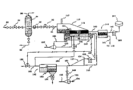
N~xt referrin~ to Fiç~ure 2 of ~ drawin~s, a ~y~tem is described
for sohJin~ ~imilar prob-i0ms in a di~ent ~onment which invdv~; ~ use
of separation equipmer~ for ~para~r~ ~uid compor~rlts of a drillin~ fluid
25 system ~or use in drillin~ oO wells. R~f~rrin~ ~w to Fi~ure 2 of ~e draw~n~s
a drilling fluWs sep~r~ion system is shown ha~lin~ a choke manHold ~ which
provides for ultirnata control over pressurQ b~ween the wellbore and the
sspara~ion systern. A separa~or 84 rea3iYes flulds from the cir~lation systern
of the convanUonal drillin~ system and in ~e drillin~ oper~ion descr;ibed herein30 the prassure ~r~m the well bein~ drilled is hJlly or par~ally pas~d in~o the
separator 84 which then ~rves as a choke on ~h~ sy~am. Such a separa~or
2 0 8 6 ~ 2 ~) PC~/Us9l~D2,ll1s
~ 14-
vess0~ i~ capabl0 of w~in~ rel~ively hi0her pr~ur~ n exarnple, ~he
Ansi Cl~ 60~ ve~ls will accar r~ate pres~ur~3 up to 1,~0 p~i. In ~e
~eparatc3r 8~ most of the ~a~ which ~ produ~ ~s liberat~ ~rom ~9 nu,~
which ~as can be.flared or passed to a ~ reoëMn~ tem for ~ubseque~
disposal ~r~h ~e ii~ 86. ~so, in ~e $~ 4, ~oli~ which may ~ in
the fo~n of a fine pa~te of drUlir~ or lth4 lilce, ~wh $~ when drlUir~ ~s
per~orrned in a chalk fonrlation, may ~r~vfty ~pEuate frorn Ule fluids to ~he
throu~h line 88 to allow ~e soUds to ~ to a pit for ~sal ~f the solk:l finesA
A Isvel control 90 ~pen~ ar~ cl~ ~ v~0s ~2 to m~intain a l!quid bvei ~
th9 ~p~rator 84 to keep ~a~ ~ve ~ low~ bvel ~ the ~p3~ator and thus
prover~ as as much a~ po~le from ~ out Irtto ~ r~r o~
separator sy~tem. ~f the liqu~ bvsl ~f s~tos 84 ~W ~1 behw a desired
lavel, th~ liquid lev01 conbol ~0 wiU c~ ~ valv~ 92 ~ perlr~t a bu~p ~f
fluids w~hin ~he ~parator and ~reby keep ~e ~as bvel at a ~ien~y hi0h
posi~n in ~e separa~or.
The fluids exitin~ separ~or 84 ~e passsd throu0h valves ~2 to
a holdin~ tank 11~ which typically is a large por~bb ~k ~ can be mov~
easily. The ~ank l 16 ~ n~ ~ pressLtre v~l r~rnaliy but 1~ ~d and ~
a fan to draw ~ as ~r~0h a ~ck 117 f~r ven~n~ to ~e ~wsph~re. The
tank 116 provides a fir~t qubt zor~ 11 û $o ~t ~ ~tkls or fi~ in ~ fluids
a~ point may gravi~y saparate ~o the bot~om ~f tank 116. A ~or portion
of the solids may be remov0d frorn ~ drillin0 fluids Tn ~e tank 116. Th 3se
solids ars then pumpad or drained from the ~ttom ~f tank 116 ~rou~h line
124 ~o a soiid/liquid ~ntrHuge separator 118 which separ~tes solids from
liquids ther0in, w`~h the solid ~mponen~s frorn the ~epar~tor 113 p~ssin~ to a
p~t, not shown, through underF ow ou~0t 1~. Water and oil from tha centrifu~e
1 18 are then pass;ed back ~o an overfl~w charnber 11~ in the tank 11~ wher~
Uley join the oil land water ~mpone~ th~t spili over the bafFle 121 into
chamber 119.
Tank 116 is arranged to control the level ~ oil and wa~er layers
.
w0 92/193~8 . ~ 1 3~r/U~ 6~
21~8~32Q
96, 98 resp~ctiv01y in U~e tank, u~in~ a level control 1~3. The ~op of ~e uil l~yer
98 in chamber 119 of tank 1 16 ~s pa~d ~rou~h a line 140 to a ~ttlin~ ~k
142 for fur~r sepa~ation b~ora pumpin~ to ~ales repr~ ted by the ~k
141. Any water taken from ~e sur~e tarlk 142 is p~s~ back to the water
iayer 98 of ~ank 116 by way of line 141.
tt has b~n fcwnd ~at pa~aJlate rr~er in t~ drill cuttings su
as particles of ~Ik become we~ted by the pr~duced oil whioh pass0~ from ~he
formatior~ i~ein~ dAU~ Ir~to ~ ~illin~ flUKl~ ~tream. Tl~ ~lid par~ thus
form a nudeus which when ~overed wi~h oil becomes a neutraliy buoy~
particle that form~ the basi~ ps~or or emu~ior layer in ~ fluid
mixture. Thus, the w~ter ph~a th~ aken from tank 11~ whlch pas~
~hrou~h line 146 ir~to ~e hl0t 134 of a hydrocyclsne 147, has such neubralll~
buoyant ~l ooated pa~ ~ a ~t of ~ rnak0up of the mi~du~ whi~ i~s
ini~tted to the ~rydrocyclone. An oll ~ e~ throu~h the rej~t or over~w
ou~et 45 of ~e hydrocyc~ne arKI i~ passed back to ~e oil layer 96 of ffie tanl~
11~ to er~er ~e tank ~t ~he ~op e~e oF ~e ~u~pension layer 97. Thi~
suspsnsion layer 97 beir~ ~eparated by ~e hydr~yc!ona 147 may be for
exarnple in the ran~e ~f 65% ~l and 3S9~ er but ~t ~is po nt ffle ~il ph~e
por~on of the stream repr~ ~ 1 1112 to 29C of ~e t~ fluid vol~n0 ~ ~
~0 ~ystem. A purnp 152 rr~y ~ pro~d in ~Q 1~1 l~i in ~e ~y~em ~o pr~0
sufficient inlet pr~s~ure o~ fluids er~t~rin0 ~e hydrocy~one to sffect prop~r
separation of ~he oil and water phas~s in ~he mix~ure p~in~ ht4 the
hydrocycJone. ~he underliow ou~et 151 from the hydrocyclolle 147 connec~s
with alterrlata flow paths. On~ such path passas the watar le~ to a residance
vessel 162 which servas as a rneans for separating solids ~;rom ~he primarily
wa~er a~mporlent exitin~ from ~he underflow (151~ of the hydrocydone. This
residence vessel has a weir 163 therein for trappin~ solids in a firs~ portion of
the YQ~;Sei which rnay be removed by means ~F a drain outl~ 164. The water
component passes ov~r the weir ir~o ~e re nainder of the ves~el 162 and is
outi~ d ~hrough a flow line 165 ~o a drilling fluid p~ at ~hB drill sit~ ~o aw~-~
recircula~ion in ~he driiling ~uids system. ~F ~he leYel control 143 on tank 116 is
- .
WO 92/1~34~ 2 0 8 6 3 2 O Ycr/us~ u
,
- ~6-
calling for recyde o~ the watsr stream, then this w~ter ~trearn pa~ses by w~y
of a line 166 throu~h vah~e 144 baclc to tank 11~ wl~re ~t ant~r~ ~ ta7lk a~ Dr
below the interfacb of ~e water layer 98 ar~ e er~ l~yer ~7. The ~t~
line 1165 to the dril~r~ fluW pit ~ ~d by Ir~an9 o~ con~r~l valve 168 like~0
opera~0d by the l~v~ co~trol 143. ' .
lavel of wa~er in tank 11 ô ri~ to a predetermined bv01, ti~ l~vsd control clo~
the r~ycle valve 144 and opens v~e 168l sll~ ~u~h w~ ~ be~
rec~ived with ~e i~ lRuW~ from ~e wsll. 11~, the wa~ pa~31~ from
pass4d to the drillin~ lFuW~ tank or pit ~rou~h lir~ 165. A~, wt~n ~
water l~vel in tank 11~ drop~ ~o a prK~terrri!lecl 1~, ~ ~el control 143
opens Yalves 14d" cb~3 valve 168, and th~eby malntairls 1~ oiVw~ter
Inter~ wi~hin ~ predsterml~d U~ ran~e. In ~ry, v~lves 144, 1~8 will
1~ opened and ~l in a ~r~h0 ~ashion, ~ m~n0 to r~n a rela~tiv9iy~
ant l~vel wi~in ~e pred~terrnir~ ran~e.
~tterr~ve arr~ement ~ ~hown in !Fi~we 2 for ~eatir~ fla
~nQ 1rom ~ ur~ow outl~ 151 or hydrocy~ 147. A valve 1
rn~y be opened to permit flui~ from ~ under~ to pa~s ~rou~h a flo~
750 ~o a cen~ifusal ~p~or 153 for ~n0 ~k~ tr~n ~ under~w
an underflow 155 for fu~er disposal whsrein the water componen~ ~rein
would pass by m~ f an overfls~w æu~t 154 ~or r~ireul~n in ~e dnllin~
fluids system. A still fur~her al~emaUve arran0emen~ mi~ht in~ude a
25 hydr~yclone in pla~ ~ or in add-rtion to ~ntr~u~e 153 ~r separatin~ ~he
underflow s~ream in~o solid and liquid con~ ents.
.In tlle operation of the apparéltU5 jUSlt des~bed fluids are
circulated ~om a bor~hole drillin~ opera~ion irlto the presen~ sy~tem by means
of a flowlins passin~ such fluids from the ~rehole annulus throu~h a choke
30 manifold 8Z~ These fluids are ~ypically compnsed of drillin~ FIUjdS such a~ brine,
water, or the lika; drill cuttin~s; and petroleum fluids whid~ have produced from
' ' ' ' ` ~ '
. . ... . ... .. .. . . . . .
WO 9~/193~ 2 ~ 8 ~ 3 2 1~ P~ 91/02~
. - 17-
ur~r~round ~orma~ions bain~ trav0rsecl by ~0 Iborehol0. 7h~s~ 11uids
corn~in~ the ma~seup of t~ drUI~ lquW ~y~teml are ~t~n p~ed in~o a
~para~or 84 wheYe a ~u~tar~ po~ of ~ ~as pr~t h ~ fluid~ Is
lib~d. This equiprr~nt ~s ~orn3~ called a ~a3 bd~rU. ~his llbaration
of ~8 from ~ flui~ su~ly reclL~ ue or ~ lluld~ ~ystem
so th~ fur~er pr~in~ b done at a re~ p~0s~re. ~ of ~he drili
cuttin~ in the fluid system may also ~par~ e3u~ in ~ ~,caarator ~4 and are
~n r~v~ hr ~bsequent c~ ~o~0h a 1~ 88 ~ ~he ~ttom of ~
~par~tor. A bv1 control 90 i~ op~e~y x~d h:~ Ul aL~ut lir~ frorn the
se~r ~ to pass l~ukls ~r~frorr ~ ~ ~av0 $y~m ~. Thess
vah~s are op~ by ~ ~1003~1. ~w~ di~y ~id~ ~h have r~w
a lar~e tank 11~ ~re ~y ar~ re~edl 17a ~ urnp or qL~ zona 110
separ~ed by a baflRe 121 from ~ main dwr~ ~n 11~ ~ ~ tank. l~
first qui~t zone ~e~ ~o ~ep~0 ou~ a ~I por~ ~ ~e solids in ~he
form c~f drUI cut~r~s in ~e flulds. Th~ ~lids3 ~ ed by way oF
a lin~ 124 to ~ inlet ~f a centrifu~e 118 wh eff~ve ~o separate ~ny
fluid~ in tha mab~rial~ di~r~ ~ro~h ~e 1~ from ~ ~n. The
solids are p~ed ~o a pit, or ~e Uke gr~ ~wn) ~or ~nt dispo~al.
Watsr ~ o~ ~quid~ whid~ ~re ~p~ h~ ~3e 118 ar~ d~char0ed
ro~h ~ ovsr~low 123 in~o ch~3~ber 11~ h ~ ~ank 11~. ~r0 ~ey ~3
~eated wlth ~e other fluid ~mponer~ of ~e fl~aW ~n whioh spill over
~b 121 irlto ~ber 119. 71~e ~m ~ds are permi~d ~o ~r~
separate in this chamber 50 tha~ a predomi~nt~y wat0r byer ~ develsps in ~he
~om of charnbar 119 wi~h an oil byer 9~ on ~op. An ir~terrrlediate layer 97
forrns betwe0n l~e oil and water layers and Is prindpal~ e:orrpri~ed of a
suspen~ion or emulsion oF oil and water which i~ ~tabilked by the preeence of
solid particle~. These solid par~s act ~ a nu~eLs about whieh oil collects
to thereby form a neutrally buoyant pa~ in ~e fluid ~y~em.
Th~ oil layer 96 in lthe tank 116 passe~ throu~h an GVerFIOW line
1~ exiting From ~he upper poltion of chamber 11~ whioh dir~ts the oil
WO ~)2/1934~ f~C'r/V~3~ i~4i
20~320
- 18-
oomponent ~ th0 flui~ to a ~ettlin0 ~ank 142. The sslttlin~ ~nk p~rrnit~ ~rther
demulsifiers. Any watsr w~h a~nwl~ ~n ~nk 1~2 m~y t:~0 re~r~l ~
way of a line 41 to ~he d~rr~r 11 ;tank 116 ~or 7ur~4r pr~ ir~ or
5 altern~ively, may be p~d b~c~ to ~ ~rUUn~ fluid ~y~ ~ re~ ~reu~a
An upper out3et of tank 142 i8 ~d ~ a purnp f~ b~a~er~ ~ oli to a ~k
181 ~r s;~e ~er~f.
The ~3~n~ n cw~ent ~7 u~ chamber 11~ ~ ~ken frorr~ ~
tank by way ol a line 14B and ~ ~us p~sd ~o a hydr~:y~3 1~7. ~ purr p
10 152 may be u~ o ir~ea~0 pr~swe on tha hl~ fl~ OD ~e hydr~ycl~
in order to provide suffi~ ~wirl ~o ~ ~p~ ~reh. ~K:h a pump
U.S. patant 4,~4,817.
Th~e ~uid3 p~ ttu ou~h ~ hydr~y~rH3 1 ql7 are typ~Jly
15 comprised of dropl~ ~in~ a d~ dl or water ,~e in ~ ~UOU8 ~1
or water ph~ which ~ra~e w~in ~ hydr~c~ Into ~3 r0~e
phasss. In add-~ d~d aboYe, soli~ par~ wt~ are prQ~ ire
~e drillin~ flui~ sy~em and which h~ve been ~t~ by oU b~ne neu~
bu~. m~ n0u~ y ~oyant 3ubs~ ~en pass$~ w th ~ co~nuou~
phase having ~a druplets disp3r~ ~herein. In the hydrocydona ~e oîl
~atin~ about ~he solids ~icl~ is l~rably removed by ~e ex~ssiYe 0rav~ty
for~s ~hat are pres0nt in ~o hydrocyclon0 which lib0rates ~e solids particle
25 thus providin~ a less dense oil ~mponent and a rnore den~e solids p~eO
The ~olid par~cles then combin0 wi~h ~e mo~ dense wa~er phase and exi~ ~e
hydrocyolon0 through the underFlow o~nl~ 151. This underflow s~ream whiGlh
corr prises ~he water phase and the s~Ud par~des is 3a~ed into ~he residen~
vess01 162 ~o remove the solids ~erG~rom so ~hat the wa:~er phase oan be
30 reoirGulated into thle drillin~ fluids sys~em for reuse in ~he drillin~a operation. The
less dense oil phase is pa~sed through ~e ove~flow outl0t for rs~um ~o ~e ~ank
,
.
.
'
WO 9~/1934~ 2 0 ~ ~ ~ 2 0 ~C~/~JS!15~
119 or alternatively, coulcl be passed dire~y to sales i~ the oil phase ther0ln
were suffia~n~ly dry. tloweverl if tt~ oil phase is returned to ~e tank 11~ ~
oil tharein w~ll readily deploy to the oll layer 8B within ~ ~rnber 119 for
subsequsr~ pr~in3 of the o~l phase passu~ ~efrom.
The hydro~clona 147 wh~ shown u~ tem w~
typicaliy ba a d~w~terul~ hydrocy~one or a deoil~n~ hydrocychne whlch
arranged to handle a su~iaJ amount ~ water, ~d which ~e des~r~b~
more ~ic~ry in Un~d SSate~ p~e~ 4,74~,~0 an~d Ur~ted Sta~ pat~
~pplica~on Serial No. 415,316. In E~n anerna~ve arr~e~sr~ the hydrocyctor~
40 of F~ure~ 1 ancl 3 ar~ hydrocyck~ 147 *~ in F~ure 2, rnay be ~ ~
~y~ discl~ in lJ.S. P~tsnt 4,810,382 wl~ ~8 In~ed t~rein by
re~erence and which sh~ a circL~ren~al 81~ ~ h ~ outer ~Hall
the hydrocyolone which ~ effe~ve to ou~et ~olid~ into an ~nular ~alb~y ~
sepasate removal from ~a hydrocydone. ~er arrang~r~r~ for ~olids
ramov~ ~orn a hydrocy~nQ ~et are, o~ cowse, not pr~luded.
~r~re, while pa~ embod~r~ of 1~ present in~r~
h~e b~en ~wn and dc~crlbed, It ~ apparent~t Ctl~ ænel rnodi~tlo~
may be made wi~out depar~ from thi~ ~n in ~ bro~r aspæ~
~refore, ~e aim in ~ ~pended elaim~ i~ to c~ver aJI ~ d~n~ ~1
modifir~ions as fall wiff~in ~e ~e ~pir5t ancl ~CoF~ of ~ u~v~n~ion.
We dairrl: