Note: Descriptions are shown in the official language in which they were submitted.
2086408
!!y. ;~...V.
Description
FIBER-OPTIC ANTI-CYCLING DEVICE FOR STREET LAMPS
Technical Field
The invention disclosed here generally relates to
electrical controls, and is specifically directed to high
pressure sodium lamps or luminares that are used in street
lights and in high bay lighting of interior spaces. More
particularly, the invention relates to controls that are
operable to detect and shut off the power to such lamps in the
event they abnormally cycle as a result of sodium depletion or
other causes.
Background Art
High-pressure sodium lamps are well-known in the lighting
field, and are currently in wide use by many public utilities
for street lighting purposes. Although such lamps have a long
life span, they eventually fail after an extended period of use
because of sodium depletion. As the skilled person would know,
the sodium inside the sealed glass bulb of this type of lamp
becomes depleted to-a point where lamp voltages can no longer
maintain a continuous arc~~aithin the bulb. Furthermore, over
a period of time, plating materials on lamp elements eventually
cause a darkening on the inside of the bulb glass, which has
a contributing effect to any given lamp s ability to maintain
an arc as a result of sodium depletion. These factors
typically create an abnormal cycling condition where the lamp
continually flashes or attempts to start.
If abnormal cycling is allowed to continua for a long time, ~
it eventually damages the lamp s starter/ballast unit,
typically by burning out the ballast. When this happens, not
only must the depleted lamp bulb be replaced, but the
starter/ballast unit must be replaced as well. Having to
replace the latter unit is expensive and creates higher overall
costs of repair.
Further, in many modern light fixtures that fall within the
high pressure sodium lamp category, electrical current
1
CA 02086408 2001-12-05
continues to be used from the power lines even when t:he lamp
is not illuminated or i.s otherwise completely burned out.
Even worse, some l::i.xtu~~es have ballasts that draw higher
levels of current when t:he lamp is burned out than i.t would
otherwise draw when 'the lamp is burning properly. In either
case, the end result. is an unnecessary waste of power, making
it important to detect and stop an abnormal cycling condition
as soon as possible.
The inventor .named here is also named as a co-inventor in
US Patent No. 5,103,137 which issued on April 7, 1992.
As was discussed in LJS Patent No. 5,103,137, few
inventors or companies h~~ve successfully addressed the above-
described cycling problem. The patent literature, for
example, discloses t:ruat only a handful of inventions have been
developed that directly relate to the problem, most of which
issued within the last five years. In this regard, at the
time US Patent No. 5,103,137 was filed, US Patent Nos.
4,207,500 (issued to Duva et al OT1 June 10, 1980); 4,473,779
(issued to Lindner et. al on September 25, 1984); 4,810,936
(issued to Nuckol_L: et al on March 7, 1989) ; and 4, 853, 599
(issued to Singarayer om August: 1, 1989) fairly represented
the state of the az.-t re:Lative t;o anti-cycling detection and
control. Since that: time, US Patent Nos. 4,881,012 (issued to
Almering on November 14, 1989); 4,949,018 (issued to Siglock
on May 28, 1990) and 5,C19,751 (issued to Flory and Nuckolls
on May 28, 1991) have also issued, and thus represent more
recent attempts at. solving the same problem.
The fact that most ~~f the relevant patents in this field
of technology have issued only recently illustrates how the
lighting industry i.s now beginning to recognize the cycling
problem, and t:he pot.ent:ial commercial returns that will be
realized by the first ir._ventor or company to develop a cost-
effective, anti-cyc:l:irng device. As of yet, it is not believed
that anyone has successfully met this need.
In order to be suc~=:essful, an anti-cycling device must
2
CA 02086408 2001-12-05
have the following characteristics: First, its cost to the
end user, i.e. the 7..igh1=.ing companies, must be sufficiently
low in comparison t:o the replacement costs of starter/ballasts
and lamp bulbs. Second, the installation time and labor for
retrofitting exists.n.g lamps must be minimal. Lastly, the
device must operate properly, regardless of the lamp or
starter/ballast type.
During the course of attempting to implement the
invention disclosed in US Patent No. 5,103,137 referenced
above, it was discovered that the subject invention had
drawbacks relating to all three of the above characteristics.
Although it is believed that i.t does provide anti-cycling
control circuitry that is extremely simple with respect to
implementing the de-activation of a power supply to an
abnormally cycling lamp, the mode by which cycling was
detected could not be universally applied to all types of
high-pressure sodium lamps. Further, it was designed to be
installed as a separate unit. inside the housing of a
conventional street: light. This entai7_ed an unacceptable
burden on the end-user, because of the labor and time involved
in physically mounting the unit inside the housing, and making
the necessary electrical connections to the high-voltage power
lines. It is believed that many or most of the devices
disclosed in the other patents referenced above have many of
the same drawbacks.
As will become apparent, the invention disclosed here
represents an improvement over and above the invention
disclosed in US Patent No. 5,103,137 and the various other
inventions referenced above. With the exception of the
invention disclosed i.n U:~ Patent No. 5, 019, 751, it is believed
that prior attempts at solving the anti-cycling problem have
always involved detecting a cycling condition by sensing
changes in line c~zrr.-ent~ or voltage levels. The present
invention represents a complete departure from. these
techniques. As will become apparent, the present invention
3
CA 02086408 2001-12-05
provides an anti-cycling device that is light-triggered. That
is to say, the light from the lamp itself, as opposed to the
current and voltages which cause t=he lamp to
3a
~U8b408
burn, is what triggers the present invention. How the
present invention works, including its advantages, will
now be discussed and described below.
Summary of the Invention
The present invention is an anti-cycling device
having an anti-cycling controller or anti-cycling control
circuitry that is operable to cut off the power supply to
a high pressure sodium lamp once an abnormal cycling
condition has been detected. In accordance with the
invention, cycling is detected by a light sensor that
inputs a light-triggered signal to the controller as the
lamp goes on or off, corresponding to the lit and unlit
conditions which normally occur when the lamp cycles.
The light sensor is adapted to directly receive light
that is emitted from the lamp. In other words, the
sensor generates the cycling or triggering signal by
sensing light that is emitted from the lamp itself,
instead of sensing changes in current and voltage that
also occur during lamp cycling.
The present invention therefore provides for use in
connection with a high-voltage, high-pressure sodium
lamp, said lamp being connected to a power supply that is
operable to cause said lamp to emit light, an anti-
cycling device for cutting off power to said lamp in the
event said lamp cycles on and off in an abnormal manner,
said anti-cycling device comprising:
an anti-cycling control circuit portion, said
control circuit portion being operable to selectively cut
off the power supply to said lamp; and
a light sensor adapted to view light that is emitted
by said lamp, said light sensor being operably connected
to said anti-cycling control circuit portion, and
operable to generate a light-triggered cycling signal
that is received by said anti-cycling control circuit
portion, for enabling said control circuit portion to
detect an abnormal cycling condition of said lamp, and to
4
~u8b408
cut off the power supply to said lamp in response to said
abnormal cycling condition.
In preferred form, the light sensor comprises a
fiber-optic cable that extends between the anti-cycling
controller and the lamp. An outer end of the cable is
positioned so that at least some of the light emitted by
the lamp is transmitted along the cable to the
controller. A photocell at the other end of the cable
generates an electrical signal that varies as light is
transmitted or not transmitted through the cable, as the
case may be, corresponding to lamp cycling. Such signal
is input into the anti-cycling circuitry making up the
controller, and enables the controller to thereby detect
and determine whether or not the lamp is cycling
abnormally. When an abnormal cycling condition is
detected, the controller causes the lamp's power supply
to be cut off.
The present invention also provides a power
supply/anti-cycling control unit for a street light, said
street light having a high-pressure sodium lamp received
within a street light housing, said lamp being connected
to a power supply that is operable to supply starting and
operating current and voltages to said lamp, said street
light housing further having a lens in a lower side
thereof through which light emitted by said lamp is
transmitted onto a ground area that is normally below
said housing, and a reflector wall within said housing
that substantially surrounds said lamp, for directing
said emitted light downwardly through said lens, and an
electrical socket fitting positioned in an upper side of
said housing, said power supply/anti-cycling unit
comprising:
a unit housing having a cylindrically-shaped base
portion that is connectable to said electrical socket
fitting, said unit housing having first and second light-
transmitting windows spaced apart from each other;
5
~~$~408
an ambient light photocell received within said unit
housing adjacent the first window, for receiving ambient
light from outside said unit housing;
a warning light positioned adjacent the second
window, for emitting a visible light signal to a
maintenance person when said anti-cycling unit detects an
abnormal cycling condition of said lamp;
a power supply board received within said unit
housing, said power supply board carrying power control
circuitry that is responsive to electrical signals from
said ambient light photocell, for either activating or
de-activating said power supply to said lamp in response
to whether or not said photocell signal indicates night
or day;
an anti-cycling board also received within said unit
housing, said anti-cycling board carrying anti-cycling
control circuitry that is operable to determine said
abnormal lamp cycling condition, and to signal said power
control circuitry to a de-activate said power supply to
said lamp and to illuminate said warning light in the
event said abnormal lamp cycling condition is detected;
and
further including a light sensor adapted to receive
light emitted from said lamp, said light sensor being
operably connected to said anti-cycling control
circuitry, said light sensor being operable to generate a
light-triggered cycling signal that is received by said
anti-cycling control circuitry, for enabling said anti-
cycling control circuitry to determine said abnormal
cycling condition.
In a further embodiment, the present invention
provides a device for preventing a high-voltage lamp from
abnormally cycling, the device comprising:
an anti-cycling control circuit portion operable to
cut off the power supply of the lamp in response to
receipt of a cycling malfunction signal; and
5a
~i~864~8
a light sensor having a fiber-optic cable, one end
of the cable being arranged relative to the lamp in a
manner so that the cable receives and conveys at least
some of the light radiation emitted by the lamp, the
light sensor including a photocell arranged relative to
the outer end of the cable in a manner so that the
photocell receives at least some of the conveyed
radiation, the photocell generating an electrical output
that cycles in correspondence with abnormally cycling
lamp radiation conveyed by the cable, and the output of
the photocell being used to produce the cycling
malfunction signal.
The various advantages of the invention will become
apparent upon review of the following description which
should be read in conjunction with the drawings.
Brief Description of the Drawings
In the drawings, like reference numerals and letters
refer to like parts throughout the various views, unless
indicated otherwise, and wherein:
Fig. 1 is a pictorial view of a conventional street
light fixture, looking down on top of the housing for
such fixture, and shows how a power supply/anti-cycling
unit in accordance with the invention is mounted to an
existing electrical socket fitting on top of the housing;
Fig. 2 is a pictorial view of the fixture shown in
Fig. 1, but looking from a lower side thereof, and shows
the lower half of the fixture housing in an open
condition for accessing various components within the
housing;
Fig. 3 is an enlarged pictorial view of the anti-
cycling/power control unit shown in Fig. 1;
5b
X086408
b < <,
Fig. 4 is a side cross-sectional view of the unit shown in
Fig. 3;
Fig. 5 is a side view of the unit shown in Figs. 3 and 4;
Fig. 6 is another side view of the unit shown in Figs . 3-5;
Fig. 7 is a top plan view of the unit shown in Figs. 3-6;
Fig. 8 is a bottom plan view of the unit shown in Figs.
3-7;
Fig. 9 is an assembly drawing of the power control board
that is received within the unit housing shown in Figs. 3-8;
Fig. 10 is an electrical schematic of the power control
circuitry which is mounted to or carried by the power supply
board shown in Fig. 9;
Fig. 11 is an assembly drawing of an anti-cycling control
board which is also received in the unit housing shown in Figs.
3-8; and
Fig. 12 is an electrical schematic of the anti-cycling
control circuitry which is mounted to the board shown in
Fig. 11.
Best Mode for Carrying out the Invention
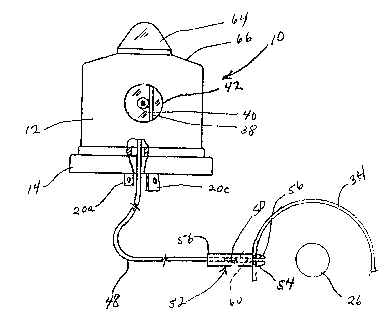
Referring now to the drawings, and first to Fig. 1, shown
generally at 10 is a power~~~supply/anti-cycling control unit in
accordance with a. preferred embodiment of the invention.
Referring now to Fig. 3, the unit 10 includes a hollow housing
12 that is generally cylindrical in shape. A base portion of
the housing, indicated at 14, is shaped for mounting the
housing directly to a pre-existing electrical socket fitting
16, the latter being conventional in nature and is typically
found on top of most or all modern street light fixtures 18
(see Figs. 1 and 2).
Three electrical prongs 20a, 20b, 20c extend downwardly
from the base portion 14 of the unit 10, and are inserted into
corresponding slots 22a, 22b, 22c in the socket fitting 16.
After insertion, the unit 10 is turned to lock it in place
relative to the lamp or light fixture 18. Such connection is
conventional, and would be familiar to the skilled person. The
electrical prongs 20a, 20b, 20c electrically connect the unit
6
2~08fi~08
...
to the power lines which supply high voltage and current to
the light fixture 18, including the ballast/starter 24 (see
Fig. 2) and high-pressure sodium lamp 26 within the fixture's
housing 28.
5 A person skilled in the art would be familiar with the
light fixture 18 as it is depicted in Figs. 1 and 2 and
described above. The skilled person would also know that the
fixture housing 28 is hinged, as indicated at 30, and may be
opened to reveal the various elements or components 24, 26
10 located inside. As mentioned above, the electrical socket
fitting 16 is located on an upper or top side of the housing
28. In the lower side, a conventional lens 32 is positioned
adjacent the lamp 26. The lamp 26 is also surrounded by a
reflector 34, a portion of which is schematically shown in Fig.
5. Light from the lamp 26 and reflector 34 is transmitted
downwardly through lens 32 to an area that underlies the lamp
fixture 18.
Referring now to Fig. 4, the power supply/anti-cycling
control unit 10 has a power supply board 36, and an anti
cycling control board 38, both of which are received within the
unit's housing 12. The power supply board 36 is better seen
in Fig. 9. Directing attention there, it is generally circular
in shape, and carries the electrical elements or parts which
make up the power control circuitry shown in Fig. 10. The
above-described connection pins 20a,.20b, 20c extend downwardly
from the power control board 36, and connect into the lamp
power line as schematically shown in Fig. 10. The circuitry
of Fig. 10 either enables power to be supplied to the
ballast/starter 24, or cuts it off, depending on an electrical
signal~received from a photocell 40, the latter also being
identified by part number °PC1~~ in Fig. 11. Such photocell 40
is positioned adjacent a first light-transmitting window 42 in
a side of the unit housing 12.
Referring now to Fig. 4, the anti-cycling control board 38
is vertically upstanding with respect to the power supply board
36. It is mounted directly to the power supply board 36 by
suitable mechanical connections that are electrically non
7
2086408
..
conductive. The photocell 40 described above is moulted
adjacent a side edge 43 of the anti-cycling board 38, in a
position so that it is adjacent to and will view ambient light
directly through side window 42 (see Fig. 5).
The anti-cycling control board 38 carries the elements or
parts making up the control circuitry shown in Fig. 12. The
"POWERON" output in Fig. 12 corresponds to the same input in
Fig. 10 and, as the skilled person would recognize, shows how
the photocell 40 signals the power control circuitry to either
supply or cut of f power, depending on whether the ambient light
corresponds to night or daytime conditions. A fiber-optic
cable input,-which is indicated generally by arrow 44 in Fig.
12, provides a triggering input to the anti-cycling circuitry
shown in Fig. 12, and enables the anti-cycling circuitry to
detect lamp cycling, and to cut off power to the lamp in the
event a cycling condition is detected. This will now be
described in further detail below.
A second photocell unit 46 is mounted directly to the
anti-cycling board 38, in the location shown in Fig. 11. Such
unit is also indicated by part number "D350". One end of a
conventional fiber-optic cable 48 is connected to such unit,
and extends downwardly through the power supply board 36, and
out through the base portion of the unit housing 12 in the
manner shown in Fig. 5.
When the unit 10 is installed or mounted on top of the
light fixture 18, as shown in Fig. 1, the fiber-optic cable 48
extends all the way from the unit 10 to the reflector 36 inside
the light fixture 18. The position of the cable 48 within the
fixture housing 28 is best seen in Fig. 2. As the unit 10 is
mounted, an outer or light-receiving end 50 of the cable 48 is
passed through a small opening 49 in electrical socket fitting
16. It is believed that most fixtures like fixture 18 shown
in Figs. 1 and 2, which are presently in use, already have an
opening like opening 49, which makes it easy to extend the
cable 48 down into the fixture housing as the unit 10 is
installed. If not, it would be a relatively simple matter to
create a suitable opening through the socket fitting 16.
8
2086408
.. __:
The outer end 50 of the cable is mounted to the reflector
34 via another fitting 52. Such fitting 52 has a forward
portion 54 that is snap-fit into an opening 56 made through the
wall of the reflector 34. When installing the unit 10 for the
first time in a retrofit situation, the maintenance person
would normally create the reflector opening 56 for
accommodating the snap-fit connection just described. The
fiber-optic cable's outer end 50 is crimped into an outer
portion 58 of the fitting 52, and is thereby held in position
a certain distance that is spaced outwardly from the reflector
36.
As the skilled person would know, the reflector 36 heat s
up substantially after the lamp 26 has been running for a
certain period of time. In order to protect the fiber-optic
cable 48 from being exposed to unacceptable levels of heat, it
is necessary to space it from the reflector or otherwise
insulate it in some manner. Spacing the cable's end 50 from
the reflector via fitting 52 accomplishes this purpose.
Further, the fitting 52 should preferably be made of a
substantially low heat-conducting material such as, for
example, a polycarbonate material. In addition to being low
heat-conducting, the fitting 52 should also be opaque to the
transmission of infrared light.
The fitting 52 defines a light-transmitting passageway 60
through the reflector 36 and into the cable's outer end 50.
When the lamp 26 is burning, some of its light will therefore
be transmitted through fiber-optic cable 48 to the photocell
46 mounted on the anti-cycling board 38.
When the lamp 26 cycles, the corresponding "ON" and "OFF"
light signal that is transmitted by the fiber-optic cable 48
causes the photocell 46 to alter its output, and thereby
transmit an electrical signal that corresponds to cycling.
Referring again to Fig. 12, such signal triggers a loadable
counter U1 every time light in the fiber-optic cable goes from
"ON" to "OFF". Upon receipt of the third triggering signal,
the counter Ul outputs an error signal to a norgate U3, which
9
~08~408
in turn signals the power supply circuitry shown in Fig. 10 to
cut-off further power to the fixture 18.
At the same time, the counter U1 also activates LED D1
which is mounted to an upper edge 62 of the anti-cycling board
38. LED D1 is positioned adjacent a second window 64 in the
top portion 66 of the unit housing 12. The LED D1 serves as
a warning light that remains on during the following day, and
would be visible through window 64 to a maintenance person,
thereby informing him or her that the fixture 18 is cycling or
is otherwise malfunctioning.
Table I below sets forth a parts list for the various
electrical components mounted to the anti-cycling board 38.
Such components should be viewed as the anti-cycling controller
portion of the power supply/anti-cycling unit 10. The part
numbers in Table I correspond to like part numbers in Fig. 12.
Fig. 12 is a schematic of the anti-cycling control circuitry
which is mounted to or carried by the anti-cycling board 38.
An assembly drawing of such board is shown in Fig. 11, which
also depicts the same part numbers that are displayed in Fig.
12 and in Table I.
2086408
y i
TABLE I.
ANTI-CYCLING LOGIC BOARD
BILL OF MATERIALS
Quantity Reference Part DESCR MFG Part Number
3 C2, C3, C10 .33uF CAP SMT KEMET C1825C334M5RAC
1 C800 1000uF CAP T/H MEPCO 3476HF102MOlOJDIBS
1 R3 68 RES SMT DALE RC1206XXXJ
1 R4 1K RES SMT DALE RC1206XXXJ
2 R8, R13 2K RES SMT DALE RC1206XXXJ
1 R18 5K RES SMT DALE RC1206XXXJ
2 R5, R10 lOK RES SMT DALE RC1206XXXJ
2 R11, R12 20K RES SMT DALE RC1206XXXJ
1 R7 22K RES SMT DALE RC1206XXXJ
2 R19, R20 33K RES SMT DALE RC1206XXXJ
1 R9 36K RES SMT DALE RC1206XXXJ
3 R2, R6, R16 100K RES SMT DALE RC1206XXXJ
2 R21, R22 200K RES SMT DALE RC1206XXXJ
1 8185 100K POT POT 100K BOURNES 3296X-1-104
1 Q1 2N3906 TRANSTR SMT MOTOROL MMBT3906LT1
1 D3 1N4148 DIODE T/H MOTOROLA
1 D1 LED LED STANLEY H2000L
1 D350 MFOD71 LIGHT SENSOR T/H MFOD71
1 PC1 PC PHOTOCELL
T018
SILONEX
NSL-4172
1 U2 LM339 QUADCMP SMT MOTOROLA LM339D
1 U3 4001 QUADNOR SMT MOTOROLA MC4001BD
1 U1 14161 COUNTER
SMT
MOTOROLA
MC14161BD
Likewise, Table II below sets forth a parts list for the
i
various electrical components mounted to the power supply board
36. Such board 36 should be viewed as the power controller
portion of the power supply/anti-cycling unit 10. The part
numbers in Table II correspond to the part numbers shown in
Fig. 10. Fig. 10 depicts the power supply control circuitry
which is carried by the power supply board 36. Fig. 9 is an
assembly drawing of such board 36, and also displays the same
part numbers that are displayed in Fig. 10 and .in Table II.
11
2086408
TABLE II.
ANTI-CYCLING POWER BOARD
BILL OF MATERIALS
Quantity Reference Part DESCR MFG Part Number
1 C700 .022uF CAP PANASONIC ECQ-E10223KZ
T/H
1 C950 luF CAP 1000V PANASONIC
T/H ECQ-E10104KZ
1 C460 220uF CAP MEPCO 3476FC221MOlOJMBS
T/H
1 8101 470 RES DALE RC1206XXXJ
SMT
2 8103, 8104 1K RES DALE RC1206XXXJ
SMT
1 8102 4.7K RES DALE RC1206XXXJ
SMT
1 8680 MOV VSTR 400V PANASONIC ERZ C10DK681U
T/H,
1 Q101 2N2222 TRANSTRSMT MOTOROLAMMBT2222LT1
1 Q200 MOC3083 OPTOISLTR
SMT
MOTOROLA
MOC3083
1 Q775 MAC22810 TRIAC MAC22810
T/H
MOTOROLA
4 D101,D102,D103 ,D104 1N4004DIODE
T/H
MOTOROLA
1 D105 1N4101 DIODE MMBZ5237B
SMT
MOTOROLA
1 U101 LM7805 VLT SMT MOTOROLAMC78L05
REG
1 8105 1 WATT
The skilled person, having the benefit of the information
listed on Tables I and II, along with the electrical schematics
shown in Figs. 10 and 12, could easily ascertain how the
invention works, and could easily build it in the form depicted
in Figs. 1-5, or otherwise adapt the circuitry of Figs. 10 and
12 to a different form of power supply/anti-cycling unit.
The fitting 52 which is connected to the reflector 34; the
fiber-optic cable 48 which extends from the fitting 52 to the
photoc'~11 46 on the anti-cycling control board; and the
photocell 46 itself, together define a light sensor that is
operable to create a light-triggered signal that is input to
the anti-cycling controller or, in other words, the anti-
cycling control circuitry shown in Fig. 12. Unlike other anti-
cycling devices, the controller or control circuitry shown in
Fig. 12 is therefore not triggered by monitoring voltage or
current that is supplied to either the ballast/starter unit 24
or the lamp 26 of the light fixture 18. Instead, it is the
12
2086408
light which is emitted directly by the lamp 26 itself,
transmitted via fiber-optic cable 48, which provides the
triggering signal. Detecting anti-cycling in this way,
eliminates any need for more complicated voltage and/or current
sensing methods.
The above description sets forth the best mode for carrying
out the invention claimed here as it is presently known. It
is conceivable that there will be future improvements and/or
modifications to the power supply/anti-cycling control unit
described above. For this reason, the preceding description
should not be viewed as limiting the scope of what is intended
to be the invention. Instead, the scope of the invention is
to be limited only by the subjoined claims which follow, the
interpretation of which is to be made in accordance with the
established doctrines of claim interpretation.
13