Language selection

Search

Patent 2086557 Summary

Third-party information liability

Some of the information on this Web page has been provided by external sources. The Government of Canada is not responsible for the accuracy, reliability or currency of the information supplied by external sources. Users wishing to rely upon this information should consult directly with the source of the information. Content provided by external sources is not subject to official languages, privacy and accessibility requirements.

Claims and Abstract availability

Any discrepancies in the text and image of the Claims and Abstract are due to differing posting times. Text of the Claims and Abstract are posted:

  • At the time the application is open to public inspection;
  • At the time of issue of the patent (grant).
(12) Patent: (11) CA 2086557
(54) English Title: LOUDSPEAKER SUSPENSION
(54) French Title: SUSPENSION DE HAUT-PARLEUR
Status: Term Expired - Post Grant Beyond Limit
Bibliographic Data
(51) International Patent Classification (IPC):
  • H04R 7/20 (2006.01)
  • H04R 7/16 (2006.01)
  • H04R 9/06 (2006.01)
(72) Inventors :
  • HOUSE, WILLIAM NEAL (United States of America)
(73) Owners :
  • HARMAN INTERNATIONAL INDUSTRIES, INCORPORATED
(71) Applicants :
  • HARMAN INTERNATIONAL INDUSTRIES, INCORPORATED (United States of America)
(74) Agent: OYEN WIGGS GREEN & MUTALA LLP
(74) Associate agent:
(45) Issued: 1994-10-25
(86) PCT Filing Date: 1991-07-11
(87) Open to Public Inspection: 1992-01-12
Examination requested: 1992-12-30
Availability of licence: N/A
Dedicated to the Public: N/A
(25) Language of filing: English

Patent Cooperation Treaty (PCT): Yes
(86) PCT Filing Number: PCT/US1991/004909
(87) International Publication Number: WO 1992001359
(85) National Entry: 1992-12-30

(30) Application Priority Data:
Application No. Country/Territory Date
07/551,201 (United States of America) 1990-07-11

Abstracts

English Abstract

2086557 9201359 PCTABS00010
A transducer comprises a diaphragm (20) including a perimeter
(22), a motor (28) for causing the diaphragm (20) to vibrate in
response to an electrical signal corresponding to program material to
convert the electrical signal to motion of the diaphragm (20)
and thus to an audio reproduction of the electrical program
material signal, and a surround (24) and a frame (26) for supporting the
diaphragm (20) from its perimeter (22) to permit such motion.
Additional diaphragm (20) supports (44, 46) are provided on the
frame (26) and project from the frame (26) toward the diaphragm
(20). Additional compliances (40) are provided on the diaphragm (20)
and are coupled (52, 54) to the additional diaphragm supports
(44, 46). The additional compliances (40) are located adjacent the
additional diaphragm supports (44, 46).


Claims

Note: Claims are shown in the official language in which they were submitted.

Claims
1. A transducer comprising a diaphragm
including a perimeter, means for causing the diaphragm to
vibrate in response to an electrical signal corresponding
to program material to convert the electrical signal to
motion of the diaphragm and thus to an audio reproduction
of the electrical program material signal, and means for
supporting the diaphragm to permit said motion, the
diaphragm supporting means including a frame, a
compliance for coupling the diaphragm perimeter to the
frame to support the diaphragm while permitting said
motion, a plurality of additional diaphragm support means
on the frame and projecting from the frame toward the
diaphragm, and a plurality of additional compliance means
coupled to the diaphragm and to respective ones of said
additional diaphragm support means, said plurality of
additional compliance means located adjacent said
respective additional diaphragm support means, each of
said additional compliance means having two opposed
surfaces and said additional diaphragm support means
being provided in pairs, the members of each pair of said
additional diaphragm support means extending from the
frame toward opposite locations on two opposed surfaces
of each respective additional compliance means.
2. The transducer of claim 1 wherein the
perimeter of the diaphragm is configured generally as a
closed plane curve and said plurality of additional
compliance means are located generally symmetrically
about the diaphragm with respect to the perimeter.

3. The transducer of claim 1 wherein the
diaphragm is generally flat.

Description

Note: Descriptions are shown in the official language in which they were submitted.


WO 92/013~;9 2 0 8 ~ PCI`/US91/04909
LOUDSPEAKER SUSPENSION
Backqround of the Invention
This invention relates to transducers and
particularly to a mechanism for supporting the diaphragm
of a diaphragm type, electrodynamic acoustical transducer
from the supporting fràme thereof.
Various tvpes of systems for supporting the
diaphragms of diaphragm-type acoustical transducers from
the frames of such transducers are known. The systems
described in the following listed U.S. and foreign
Patents are intended as illustrative of these various
types of systems: .
Patent N~ E Inventor~s Name Issue Date
154,817,165 Amalaha 03/28/89
4,387,275 Shimada 06/07/83
4,821,330 Pfleiderer 04/11/89
3,919,498 Beer 11/11/75
2,478,642 Root 08/09/49
203,780,232 Ward 12/18/73
3,614,335 Tester 10/19/71
4,554,414 House 11/19/85
3,718,779 Schoengold 05/27/73
3,531,602 Brown 09/29/70
253,711,659 Bremseth 01/16/73
4,317,965 Toyoda 03/02/82
3,596,733 Bertagni 08/03/71
3,073,411 81eazey 01/15/63
**2,074,419A Kakiuchi 10/28/81
**British Patent Specification
This listing is not intended as a representation that a
thoroùgh search of all relevant prior art has been
: conducted, or that no closer prior art exists.
Of these patents, Amalaha, U.S. Patent
4,817,165, Shimada, U.S. Patent 4,387,275 and Pfleiderer,
U.S. Patent 4,821,330 appear to be the most pertinent.
Figs. 1 and 12C-13C of Amalaha disclose a bellows-type

20g6~.~S7
WO92/01359 PCT/USgl/04909
suspension positioned midway between the voice coil form
and the dome surround. Figs. 8, 9, ll and 13 of Shimada
disclose compliances other than the surround between the
diaphragm and frame. However, these figures also `
disclose spiders between the voice coil form and the
frame. Fig. 6 of Pfleiderer discloses ~ibration damping
elements (SD) attached to the diaphragm between the voice
coil form (P) and the surround (F). However, this
appears to be a force diagram only, and does not reflect --
the actual physical structures of the Pfleiderer
transducers. ~;
According to the present invention, the prior `
art requirement for the spider is overcome. This permits
the design of thinner acoustic transducers, in terms of
transducer depth, for those installations for which the
, . . .
need for thinner transducers is most desirable, such as,
for example, automotive vehicle door-mount installations. ~-'
According to the invention, a transducer
comprises a diaphragm including a perimeter, means for
20 causing the diaphragm to vibrate in response to an ;
electrical signal corresponding to program material to
convert the electrical signal to motion of the diaphragm -`
and thus to an audio reproduction of the electrical
program material signal, and means for supporting the
2~ diaphragm to permit such motion. The diaphragm
supporting means includes a frame, a compliance for
coupling the diaphragm perimeter to the frame to support
the diaphragm while permitting such motion, and
additional diaphragm support means on the frame and
30 projecting from the frame toward the diaphragm. ~`~
Additional compliance means are located adjacent the
additional diaphragm support means and are coupled to the
diaphragm and to the additional diaphragm support means.
Illustratively, there are a plurality of such `
3~ additional diaphragm support means and an equal plurality
of such additional compliance means. The additional
diaphragm support means and additional compliance means ~;
~,,".
:'`

WO92/013~9 2 0 8 6 ;; 5 7 PCT/USgl/04909
are p~ovided at a plurality of locations about the frame ~-~
and diaphragm, respectively.
Additionally, illustratively, the perimeter of `
the diaphragm is configured generally as a closed plane
curve and the plurality of additional compliance means
are located generally symmetrically about the diaphragm !~!~
with respect to the perimeter. In one embodiment, the
perimeter of the diaphragm is configured generally as a
closed plane curve having a center and the additional ;
compliance means is located at substantially the center.
Further, illustratively, the diaphragm has two
opposed radiating surfaces and the additional diaphragm `
support means are provided in pairs, one of each pair of
additional diaphragm support means extending generally
toward opposite locations on the two opposed radiating
surfaces of the diaphragm.
-In one illustrative embodiment, the diaphragm
is generally flat. In another, the diaphragm generally
comprises a somewhat conically shaped surface providing
an apex.
;
Brief Description of the Drawings
The invention may best be understood by
- referring to the following description and accompanying
drawings which illustrate the invention. In the
drawings:
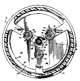
Fig. l illustrates a partly sectional plan view
of a transducer constructed according to the invention,
with the section taken generally along section lines l-l
30 of Fig. 2; ;
Fig. 2 illustrates a partly sectional
elevational view of the transducer of Fig. l, with the
section taken generally along section lines 2-2 of Fig.
l; and,
`:

2~1~65S7
WO92/013~9 PCT/USgl/04909 -
Fig. 3 illustrates a fragmentary and partly ...
sectional elevational view of another transducer :`
constructed according to the invention.
5 Detailed Description of the Drawinqs j;
In a first embodiment of the acoustical transducer '`r~'~
of the invention illustrated in Figs. 1-2, a relatively
rigid, flat diaphragm 20 constructed from, for example, a s
light-weight, foamed resin, is suspended from its
lO perimeter 22 by a surrounding compliance 24 from a frame `
26. Although the i-llustrated diaphragm 20 is circular in ~-
plan view, it is to be understood that it is not .:-
necessary to practice the present invention that the ;
diphragm be circular. A voice coil motor 28 is
15 positioned within the perimeter 22 of the diaphragm 20,
illustratively at its center 30. The voice coil motor 28
::~ includes a voice coil form 32 to which a voice coil 34 is
: fixed. Although the illustrated voice coil motor 28 is a
so-called "returnless" type, such as is illustrated in .
20 U.S. Patents 3,201,529 and, 4,868,882, voice coil motor `
28 may be of any suitable type, such as that illustrated
in published Patent Cooperation Treaty application
;: ~ PCT/US89/04501. Passage of current through the voice .:
coil 34 mo~es the diaphragm 20, in accordance with
25 well-known principles, to convert an electrical signal :`
containing program material into an audio program
material signal.
: Although the diaphragm 20 is relatively rigid,
it is useful to suspend it from one or more points 38 in
addition to the surrounding compliance 24. In prior art
diaphragms, this additional suspension is ordinarily
achieved with a centering spider which extends between
the voice coil form and one or more points on the frame.
However, use of a centering spider attached to the voice
35 coil form does require that the transducer be designed :
and constructed with sufficient depth to accommodate the
"stack" including the diaphragm and centering spider.

WO92/01359 2 0 8 6 `/ S ~ PCT/USg1/04r~ ~
-5-
While alternati~e constructions have been proposed to
minimize the height of this stack (see, ~or example,
published Patent Cooperation Treaty application
PCT/US88/00685), the present invention approaches more
closely the ideal reduction in transducer depth by
eliminating the spider. To achieve this, additional
compliances 40 are provided on diaphragm 20. In the
illustrated embodiment there are three such additional
compliances 40 oriented at ~20 intervals around the
center 42 of the circle defined by the diaphragm 20.
Each of the additional compliances 40 illustratively is
also circular and is provided in the diaphragm 20 by
known transducer construction techniques. Supports 44,
46, respectively, extend toward the opposite radiating
surfaces 48, 50, respectively, of the diaphragm 20 from
the frame 26. These supports 44, 46 are attached, for
example, by suitable adhesives, to the oppositely facing
surfaces 52, 54, respectively, of the compliances 40 to
provide additional support to the diaphragm 20 beyond
20 that provided by the surrounding compliance 24. .
In another embodiment of the invention
illustrated in Fig. 3, the diaphragm 60 is somewhat cone
shaped. As used herein, the term "somewhat cone shaped"
is intended to include diphragms which are neither flat
nor dome shaped, whether or not they are symmetrical
: about any point or any axis. The term specifically is
intended to include those diaphragms which are configured
as described in published Patent Cooperation Treaty
Application PCT/US89/02374. The configuration of the
transducer 62 is generally conventional in this
embodiment except that there is no centering spider in
the conventional location between the voice coil form 64
and the frame 68 (as indicated by the broken lines), and
the conventional, customarily flat or dome shaped dust
cap is replaced by a compliance 70. The center portion
72 of the compliance 70 is attached, illustratively by a
suitable adhesive, to a support 74 which is mounted to,

- 2U'~'i~i''1
WO9~/01359 PCT/US91/04~9
and extends forward from the front face 76 of, the center ~.
pole piece 80 of the magnet assembly 82 of the voice coil
motor 84.
: . :
.
.

Representative Drawing
A single figure which represents the drawing illustrating the invention.
Administrative Status

2024-08-01:As part of the Next Generation Patents (NGP) transition, the Canadian Patents Database (CPD) now contains a more detailed Event History, which replicates the Event Log of our new back-office solution.

Please note that "Inactive:" events refers to events no longer in use in our new back-office solution.

For a clearer understanding of the status of the application/patent presented on this page, the site Disclaimer , as well as the definitions for Patent , Event History , Maintenance Fee  and Payment History  should be consulted.

Event History

Description Date
Inactive: Expired (new Act pat) 2011-07-11
Inactive: Late MF processed 2010-07-19
Letter Sent 2010-07-12
Inactive: Correspondence - Transfer 2009-07-22
Inactive: Late MF processed 2009-07-21
Letter Sent 2009-07-13
Letter Sent 2009-07-06
Inactive: IPC from MCD 2006-03-11
Appointment of Agent Requirements Determined Compliant 2004-07-08
Inactive: Office letter 2004-07-08
Revocation of Agent Requirements Determined Compliant 2004-07-08
Revocation of Agent Request 2004-05-26
Appointment of Agent Request 2004-05-26
Grant by Issuance 1994-10-25
All Requirements for Examination Determined Compliant 1992-12-30
Request for Examination Requirements Determined Compliant 1992-12-30
Application Published (Open to Public Inspection) 1992-01-12

Abandonment History

There is no abandonment history.

Fee History

Fee Type Anniversary Year Due Date Paid Date
MF (patent, 6th anniv.) - standard 1997-07-11 1997-06-18
MF (patent, 7th anniv.) - standard 1998-07-13 1998-06-25
MF (patent, 8th anniv.) - standard 1999-07-12 1999-06-18
MF (patent, 9th anniv.) - standard 2000-07-11 2000-06-21
MF (patent, 10th anniv.) - standard 2001-07-11 2001-06-20
MF (patent, 11th anniv.) - standard 2002-07-11 2002-06-20
MF (patent, 12th anniv.) - standard 2003-07-11 2003-06-20
MF (patent, 13th anniv.) - standard 2004-07-12 2004-06-21
MF (patent, 14th anniv.) - standard 2005-07-11 2005-06-22
MF (patent, 15th anniv.) - standard 2006-07-11 2006-06-30
MF (patent, 16th anniv.) - standard 2007-07-11 2007-06-18
MF (patent, 17th anniv.) - standard 2008-07-11 2008-06-18
Registration of a document 2009-04-28
MF (patent, 18th anniv.) - standard 2009-07-13 2009-07-21
Reversal of deemed expiry 2010-07-12 2009-07-21
MF (patent, 19th anniv.) - standard 2010-07-12 2010-07-19
Reversal of deemed expiry 2010-07-12 2010-07-19
Owners on Record

Note: Records showing the ownership history in alphabetical order.

Current Owners on Record
HARMAN INTERNATIONAL INDUSTRIES, INCORPORATED
Past Owners on Record
WILLIAM NEAL HOUSE
Past Owners that do not appear in the "Owners on Record" listing will appear in other documentation within the application.
Documents

To view selected files, please enter reCAPTCHA code :


To view images, click a link in the Document Description column. To download the documents, select one or more checkboxes in the first column and then click the "Download Selected in PDF format (Zip Archive)" or the "Download Selected as Single PDF" button.

List of published and non-published patent-specific documents on the CPD .

If you have any difficulty accessing content, you can call the Client Service Centre at 1-866-997-1936 or send them an e-mail at CIPO Client Service Centre.


Document
Description 
Date
(yyyy-mm-dd) 
Number of pages   Size of Image (KB) 
Drawings 1997-11-01 3 92
Abstract 1997-11-01 1 72
Claims 1997-11-01 2 72
Descriptions 1997-11-01 6 304
Representative drawing 1999-01-27 1 19
Maintenance Fee Notice 2009-08-17 1 171
Late Payment Acknowledgement 2009-08-17 1 163
Maintenance Fee Notice 2010-07-18 1 170
Late Payment Acknowledgement 2010-07-18 1 163
Correspondence 2004-05-25 4 127
Correspondence 2004-07-07 1 14
Correspondence 2004-07-07 1 17
Fees 1996-05-01 1 39
Fees 1995-05-16 1 49
Fees 1994-05-09 1 35
Fees 1993-06-16 1 35
PCT Correspondence 1994-08-16 1 20
International preliminary examination report 1992-12-29 17 447