Note: Descriptions are shown in the official language in which they were submitted.
2 ~ 9 ~
Procedure for Automatically Determining the
Assignment of Direction-Linked Sensors to
the Directions of Movement of a Vehicle.
The invention relates to a procedure for automatically
determining the assignment of direction-linked sensors to the
directions of movement of a vehicle, whereby the measuring
device which contains the sensors and the estimating device
for evaluating the signals which are combined, form part of a
data acquisition unit, e.g. accident data-storage, installed
in a vehicle, and which is suitable for the reconstruction of
a path of movement.
The technical construction of data acquisition units of
the type specified is well known. For example, it is known
from EP 0 118 818 Ba, as shown in Figure 1 of that document,
that such devices, often in the form of a so-called black box,
not only record the data of vehicle dynamics, such as
accelerated motion in both longitudinal and lateral
directions, but may also register current information about
the state of the vehicle, e.g. turn-signal function. It is
also suggested elsewhere in the same document, that a
measuring device dependent on a magnetic field could be
integrated into a data acquisition unit for the purpose of
measuring the movement of a vehicle other than in a straight
line, which would enable the path of a vehicle to be
completely reconstructed.
~8~ ~J'i3
-- 2
To make a proper and meaningful evaluation of the signals
of these direction-linked sensors, mentioned here by way of
example, it is absolutely essential to know the place of
installation of the data acquisition unit where these sensors
are fixed in a certain arrangemen-t.
The necessity therefore arises for identifying the proper
place of installation, e.g. by marking this on the housing of
the unit. However, proper technical functioning of the unit
requires that the rules governing installation be scrupulously
followed, as the installation of the unit has to fulfil some
rather stringent requirements; when the data acquisition unit
is added at a later date, certain practical problems of
placing and positioning arise, owing to the relatively large
size of the housing, rendered necessary by the various
assemblies which are required to fit into it. There are very
few permissible locations where installation can take place,
and these are further limited by considerations of safety, and
are necessarily rather cramped to work in, and often not very
accessible for mounting. This usually results in wasted time,
and therefore creates additional expense to the user for
mounting.
This aspect is a considerable disincentive to the
voluntary installation of a data acquisition unit in a
vehicle. The purpose of the present invention is, therefore,
2~ g
--3--
to simplify the installation of the data acquisition unit, and
to make the technical functioning of the direction-linked
measuring device independent of the location where the device
is mounted.
The solution offered by the present invention is
characterized in that signals from direction-linked sensors of
the same type are compared and that by using a logical signal
combination and signal evaluation, that particular sensor will
be selected as a source of data for a particular direction of
movement of a vehicle which displays significantly different
changes in measurement when at least one further signal is
given, generated by a different functional unit of the
vehicle, which for its part is also assigned in a precise and
known manner to a particular direction of movement of the
vehicle.
The subclaims display advantageous developments of the
solution set out in the invention.
The invention has the advantage that the measuring device
for registering the vehicle dynamics which is usually
constructed with each sensory channel in duplicate, can be
built absolutely identical with respect to the sensors, i.e.
direction-neutral, and can be supplied from the factory
without it being necessary to supply any indication as to
which sensory channel is intended for the longitudinal or
lateral dynamics of the vehicle. Markings on the housing of
~ 23~o~
the data acquisition unit are no longer necessary, and
direction-linked installation rules can be dispensed with.
Also, when the unit is removed, for instance for reading the
data into an external electronic data processing device for
the purpose of reconstructing the circumstances of an
accident, it is no longer necessary to specially note the
direction-linked location where the data acquisition unit was
installed in the vehicle, which must be ~nown in order to
reconstruct the path of movement.
This aspect is likewise extremely advantageous to the
user of the data acquisition unit. This is because it enables
installation of the data acquisition unit to take place in
almost any desired position with respect to the main spatial
axes of the vehicle without danger of error. Thus, the unit
can be installed quite simply by almost anyone, without
necessarily needing to involve a specialized workshop. One
restriction which should be mentioned, however, is that owing
to the fact that the sensors are generally arranged at right-
angles to each other, those locations are not suitable for
installation where the sensor main axes are at exactly 45
degrees to the principal directions of movement of the
vehicle. It is preferable to use the two arrangements shown
in the figures.
The data acquisltion unit automatically recognizes which
part of the sensory measuring device relates to which
,' : ' ' '
2~5~98
directional components, by means of a logical signalcombination and the evaluation of significant measured
signals. No manual intervention in the hardware of the data
acquisition unit is required. Furthermore, when the device is
installed in the vehicle, no measuring or calibration is
necessary, a feature which is particularly advantageous in
applications for the general public e.g. for data acquisition
units built specially as accident memory-storage suitable for
private automobiles. The invention will now be briefly
explained once again with the aid of three figures. These
show:
Fig. 1 is a schematic diagram of the implementation of
the invention in a vehicle in combination with its flashing
turn-signal;
Fig. 2 is a schematic diagram similar to Fig. 1 with the
invention combined with the brake light; and
Fig. 3 is a schematic diagram similar to Fig. 1 with the
invention combined with an angle transmitter.
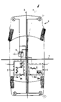
In a data acquisition unit (1) of the type mentioned
earlier, the measuring device (2) for sensory registration of
the vehicle dynamics, which can be ascertained, for example by
measuring the acceleration (a) and the magnetic field
surrounding the vehicle (b), is generally located internally
within the unit housing. In order to prevent unauthorized
access, the latter is often sealed at the factory.
-6- 2~G;-~3
No provision is generally made for the use of active
serviceable components in measuring device (2).
Particularly when data acquisition unit (1) is intended
for use as accident data-storage, the user should be in a
position to install the device (1) himself in almost any
relationship he chooses with respect to the spatial axes of
his vehicle. For instance, supposing the installation
positions to be la/2a, and lb/2b, it is then requisite that
device (1) when it begins
to operate, should automatically recognize the position in
which it was located, especially with respect to the
longitudinal axis of the vehicle (3) and the lateral axis (4).
Since all vehicles are required by traffic regulations to
activate their turn-signals when changing direction, e.g. from
direction (3) to direction (7), it is therefore advantageous
to combine this signal, for example, which shows the current
state of the vehicle, with the multi-channel sensory measuring
device (2) in data acquisition unit (1), designed specifically
for the purpose of assigning a direction.
If the flashing-light switch (5) is activated, and the
vehlcle changes its direction of travel in a time-frame
determined by the flashing signal, then one of the two sensors
of each type provided will generate a stronger signal of the
measured values than the other. ~easuring device ~2)
generally consists of two sensors of each type, arranged at
_7_ 2v~9~
right-angles to each other. The measuring device could
however be enlarged by using the third spatial axis in a
similar manner. Changes in measured values are evaluated
S duriny a time-period ~which may include the running-times
immediately preceding and/or following, depending on the time-
frame for which the flashing signal is set) by comparison of
the changes in signal which occur in sensors of the same type.
The longitudinal dynamic values, for example, do not vary
equally in value in the same significant way before and after
the time-interval set by the flashing signal.
By comparing the signal changes of both sensors, the
decision is made as to which of the sensors of measuring
device (2) is to register the lateral dynamics. Owing to the
fact that the placing of data acquisition unit (1) in the
vehicle (6), e.g. position la/2a or position lb/2b does not
generally change after its original installation, the
directional assignment may be regarded as constant once it has
been made. Nevertheless, should particular circumstances
require it, this direction-linked relationship may be checked
from time to time, or even on a regular basis in the way
described above.
Since activation of the turn-signal indicator when
changing the direction of travel is part of normal driving
procedure as laid down by traffic regulations, and movements
other than those in a straight line are usual in the operation
-8- 2 iJg VJ 9 ~
of a vehicle, the data acquisition unit reaches the state
necessary for reconstructing the path of movement in the
shortest possible time. In general, this condition is reached
as soon as the vehicle is started, or very shortly
thereafter.
In addition to signal combinations with the flashing
turn-signal, other functional and eyually effective
combinations are possible, with a view to achieving the yoal
of automatically determining the assignment of the direction-
linked sensors to the directions of movement of the vehicle.
Figure 2 illustrates another possibility. In this case, a
precise signal is generated from the braking-system of the
vehicle and picked up by the sensors assigned to the
longitudinal axis of the vehicle and thus to its usual main
direction of travel. The decision as to which particular
component of the braking system (8) is to be used for emitting
the signal can be made on purely practical grounds. As soon
as the signal - the braking signal in general for the purpose
of this example - is generated, and the evaluation unit
simultaneously detects a delay which exceeds a predetermined
threshold value, of 0.2 g for example, in one of the
acceleration sensors placed at right-angles to each other, the
measuring unit of the data acquisition unit automatically
recognizes through the combination and evaluation of these
signals, which sensor is to be assigned to the longitudinal
_9_ v~ ~JJ(j
direction, because the measured signals of the acceleration
sensors which are assigned to the vehicle's direction of
travel change in a significantly different way during the
braking process, e.g. by having a signal deviation greater
than the measured signals of the sensor of the same type
placed at right-angles to it.
Quite apart from this, Figure 3 shows yet a third
possibility of signal combination. For example, if the
vehicle is equipped with a turning-angle transmitter and this
transmitter feeds a signal to the evaluation unit of the data
acquisition device, then while the vehicle is travelling,
owing to the presence of a signal which maintains a constant
angle, preferably that of the main path of movement of the
vehicle, over a prescribed period of time, it is also possible
for assignment of the place of installation of the sensors to
the main spatial axes of the vehicle to take place
automatically, by combining this angular signal with the
measured signals of the acceleration sensor. Steering-angle
transmitters, electronic compasses or similar devices may be
considered for use as angle transmitters. Another vehicle
movement signal could also be generated by a different unit,
e.g. the tachometer (lO).
The three examples given here are by no means exclusive,
but merely serve to illustrate the idea of the invention,
namely to combine the signals from sources whose relationship
2 ~ ~ v ~, n g
--10--
to the main spatial axes of the car is known with the signals
of the measurin~ device of a da-ta acquisition unit by means of
an evaluation device, so that the direction-linked sensors of
the unit may be automatically assigned to the directions of
movement of the vehicle.