Language selection

Search

Patent 2086650 Summary

Third-party information liability

Some of the information on this Web page has been provided by external sources. The Government of Canada is not responsible for the accuracy, reliability or currency of the information supplied by external sources. Users wishing to rely upon this information should consult directly with the source of the information. Content provided by external sources is not subject to official languages, privacy and accessibility requirements.

Claims and Abstract availability

Any discrepancies in the text and image of the Claims and Abstract are due to differing posting times. Text of the Claims and Abstract are posted:

  • At the time the application is open to public inspection;
  • At the time of issue of the patent (grant).
(12) Patent Application: (11) CA 2086650
(54) English Title: MULTI-BUSHING SINGLE-PHASE ELECTRIC DISTRIBUTION TRANSFORMER FOR FEEDER PHASE CURRENT BALANCING
(54) French Title: TRANSFORMATEUR DE DISTRIBUTION MONOPHASE A TRAVERSEES MULTIPLES A COURANT DE PHASE D'ALIMENTATION EQUILIBRE
Status: Deemed Abandoned and Beyond the Period of Reinstatement - Pending Response to Notice of Disregarded Communication
Bibliographic Data
Abstracts

English Abstract


MULTI-BUSHING SINGLE-PHASE ELECTRIC DISTRIBUTION TRANSFORMER
FOR FEEDER PHASE CURRENT BALANCING
Abstract
In three-phase electric power distribution systems, kilowatt-hour
conductor losses can be reduced by keeping the current flows in all
three-phases as equal to each other as possible.
A secondary benefit of phase balancing is an improved voltage
regulation.
At present, phase balancing can be achieved by taking the phase-
current measurements, detecting a feeder with a significant current
unbalance,identifying a single-phase transformer connected to the
highest loaded phase, and then manually reconnecting it to the
lowest loaded phase. The operation involves time consuming
activities in engineering, and the deployment of personnel,
equipment and resources for its execution, plus loss of revenue
and/or inconveniences caused by an outage of several minutes
duration.
In this invention, a single-phase transformer is provided with:
three high-voltage bushings, and an internal high voltage side
three-position load-break switch. All the necessary connections are
already in place, and through the operation of the switch the
transformer load is transferred from the highest loaded phase to
the lowest loaded phase; thereby tending to an equilibrium of
circuit phase currents and therefore reducing the system losses.
The invention makes the phase-balancing process fast, easy,
convenient, safe, and economical.


Claims

Note: Claims are shown in the official language in which they were submitted.

MULTI-BUSHING SINGLE-PHASE ELECTRIC DISTRIBUTION TRANSFORMER
FOR FEEDER PHASE CURRENT BALANCING
Specification - Claims
Page 1 of 1
The embodiments of the invention in which an exclusive property or
privilege is claimed are defined as follows:
An electrical single-phase distribution transformer of any type
e.g. dry-type liquid or gas-filled; Completely Self-Protected or
non-protected; copper or aluminum windings; steel or amorphous
core; over-head or underground; pole-mounted or pad-mounted or
submersible, with two or more windings,independent or auto-
connected windings,with or without taps, with or without on-load
tap-changers,with tapered or full insulation,etc.
and with primary,secondary (and tertiary) voltage windings with
operating voltages from 1 Volt AC RMS to 250000 Volts AC RMS,
and with power capacities from 0.1 kVA to 100000 kVA,
and with two or more bushings on the high voltage side,
and with an oil, vacuum or sulphur hexafluoride insulated
internally mounted load-break switch, manually or electrically
operated - with two or more positions - to permit the transferring
of load from one of the primary phases to another.

Description

Note: Descriptions are shown in the official language in which they were submitted.


: . :
208665 0 ~ ~
MULTI-BUSHING SINGLE-PHASE ELECTRIC DISTRIBUTION TRANSFORMER
FOR FEEDER PHASE CURRENT BALANCING
Specification - Disclosure
Page 1 of 3
In a three-phase system minimum losses are obtained when all three-
phases carry equal current.
For example, a one kilometre long, three-phase line with 336.4 MCM
stranded aluminum conductors carrying phzase currents of 400 Amps,
500 Amps and 600 Amps has conductor I R losses, at 50 Degrees
Centigrade, of 144.05 kW. By balancing the current in the three-
phases, to 500 Amps each, the losses are reduced to 140.3 kW.
This invention relates to a single-phase electric distribution
transformer that with two or three high-voltage bushings and
through an internal high-voltage switch can be re-connected to
other phase(s), making the sy-~tem load more symmetrical and thereby
reducing the conductor losses on the feeder.
One, two or more units of this type,and of the same or different
kVA sizes, as necessary, can be installed on a feeder to reach a
reasonable balance of the phase currents.
The high-voltage switch can be manually or electrically operated.
The electrical operation of the switch can be effected from a local
signal (manual or automatic) or from a remotely transmitted
signal(e.g. radio, power line carrier,audio-tone, etc) manually, or
automatically originated.
The i nv enti on appli es t o utility, and
industrial/commercial/residential two orthree-phase electric power
distribution systems, with single phase transformers and operating
voltages from 1 Volt to 250000 Volts AC, RMS, phase-to-ph~se, and
a power capacity from 0.1 kVA to 100000 ~VA.
This invention can be implemented on any type of single-phase
transformer; e.g. dry-type liyuid or gas-filled, completely self-
protected or non-protected, over-head or under-ground, pole-
mounted, pad-mounted or submersible, with two or more
windings,independent or auto-connected windings,with or without
taps, with or without on-load tap-changers,etc.
The normal application of this invention in a three-phase system i9
expected to have three-bushings, but devices with only two-bushings
and a two-position switch could be also utilized in two-phase or
three-phase systems.
The internally mounted high voltage load-break switch can have oil,
vacuum or ~ulphur hexafluoride as the insulating and/or the
interrupt1ng medium.
The potential for loss reduction through phase balancing in just
North-America is enormous. Millions of kilowatt-hours can be saved
annually.
Phase balancing is currently effected by measuring the phase
currents in a circuit to detect a significant unbalance, then
finding a transformer that is connected to the highest loaded
phase, and reconnecting it to the phase with the lowest load.The
process is repeated several times until a reasonable phase current
equilibrium is reached.

- 2086~so
MULTI-BUSHING SINGLE-PHASE ELECTRIC DISTRIBUTION TRANSFORMER
FOR FEEDER PHASE CURRENT BALANCING
Specification - Disclosure
Page 2 of 3
This involves a considerable expenditure of engineering time, man-
power, equipment and tools. Due to its cost, phase balancing
actions are generally infrequent; one or two per feeder each year,
at the most.
I have found that by having on each distribution circuit one, two
or more phase-balancing transformers, the system operator can
balance the feeder by the simple expedient of measuring the circuit
phase currents, and if a significant unbalance is detected then
operating the phase-balancing transformer(s) high voltage switch to
the appropriate position.
Time, money and hassle are saved.
Depending on the level of automation, the phase-balancing
transformer can be operated locally, or remotely from a load
control or load-dispatch centre.
Additionally, automatic operation is possible. A phase unbalance
detector relay (which can be easily implemented with long existing
technology) can trigger the high voltage switch to reconnect the
phase-balancing transformer from the highly loaded phase(s) to the
low loaded phase.(s). In this level of automation, the operator is
oblivious to the changes that are occurring in the system. After
the initial investment there are no operational costs.
Automatic operation can be effected locally or remotely as well. -
The current transformerq and control equipment instead of being
mounted on or near the phase balancing transformer are mounted
remotely.
Subject to the nature of the load, freguent phase changes can be
executed, several times during the day if necessary.
The objective is always to save money by reducing losses through
phase balancing.
Recapping,this invention makes the phase balancing process easy,
quick, convenient, qafe, and economical.
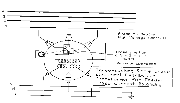
Figure No. 1 shows the connections for a three-bushing, single-
phase, phase-to-neutral connected phase-balancing transformer with
a manually operated switch.
Figure No.2 shows the connections for a three-bushing, single-
phase, phase-to-phase connected phase-balancing transformer with a
manually operated switch.
Figure No. 3 shows the connections for a three-bushing, single-
phase, phase-to-neutral connected phase-balancing transformer with
a manually or electrically operated switch. Three current
transformers are also shown feeding the control box for local
automatic control. An external connection is also indicated for
remote operation of the switch.
Figure No. 4 shows the connections for a three-bushing, single-
phase, phase-to-phase connected phase-balancing transformer with a
manually or electrically operated switch. Three current
transformers are also shown feeding the control box for local
automatic control. An external connection is also indicated for
remote operation of the switch.

6S0
MULTI-BUSHING SINGLE-PHASE ELECTRIC DISTRIBUTION TRANSFORMER -
FOR FEEDER PHASE CURRENT BALANCING .
Specification - Disclosure
Page 3 of 3
These would be the typical connections. Other are possible. For
example,a two-bushing single-phase tran~former in which the load
can be transferred from just one phase to another; rather than to ~.
two others.
~ --~ . ---. . . .....

Representative Drawing
A single figure which represents the drawing illustrating the invention.
Administrative Status

2024-08-01:As part of the Next Generation Patents (NGP) transition, the Canadian Patents Database (CPD) now contains a more detailed Event History, which replicates the Event Log of our new back-office solution.

Please note that "Inactive:" events refers to events no longer in use in our new back-office solution.

For a clearer understanding of the status of the application/patent presented on this page, the site Disclaimer , as well as the definitions for Patent , Event History , Maintenance Fee  and Payment History  should be consulted.

Event History

Description Date
Inactive: IPC from MCD 2006-03-11
Time Limit for Reversal Expired 1995-07-04
Application Not Reinstated by Deadline 1995-07-04
Inactive: Adhoc Request Documented 1995-01-04
Deemed Abandoned - Failure to Respond to Maintenance Fee Notice 1995-01-04
Application Published (Open to Public Inspection) 1994-07-05
All Requirements for Examination Determined Compliant 1993-01-04
Request for Examination Requirements Determined Compliant 1993-01-04

Abandonment History

Abandonment Date Reason Reinstatement Date
1995-01-04
Owners on Record

Note: Records showing the ownership history in alphabetical order.

Current Owners on Record
LUIS FERNANDO LLANO
Past Owners on Record
None
Past Owners that do not appear in the "Owners on Record" listing will appear in other documentation within the application.
Documents

To view selected files, please enter reCAPTCHA code :


To view images, click a link in the Document Description column. To download the documents, select one or more checkboxes in the first column and then click the "Download Selected in PDF format (Zip Archive)" or the "Download Selected as Single PDF" button.

List of published and non-published patent-specific documents on the CPD .

If you have any difficulty accessing content, you can call the Client Service Centre at 1-866-997-1936 or send them an e-mail at CIPO Client Service Centre.


Document
Description 
Date
(yyyy-mm-dd) 
Number of pages   Size of Image (KB) 
Claims 1994-07-04 1 27
Drawings 1994-07-04 4 103
Abstract 1994-07-04 1 34
Descriptions 1994-07-04 3 130
Representative drawing 1998-08-25 1 16