Language selection

Search

Patent 2086666 Summary

Third-party information liability

Some of the information on this Web page has been provided by external sources. The Government of Canada is not responsible for the accuracy, reliability or currency of the information supplied by external sources. Users wishing to rely upon this information should consult directly with the source of the information. Content provided by external sources is not subject to official languages, privacy and accessibility requirements.

Claims and Abstract availability

Any discrepancies in the text and image of the Claims and Abstract are due to differing posting times. Text of the Claims and Abstract are posted:

  • At the time the application is open to public inspection;
  • At the time of issue of the patent (grant).
(12) Patent: (11) CA 2086666
(54) English Title: TENTER FOR TREATMENT OF AN ENDLESS FABRIC
(54) French Title: TENDEUR POUR LE TRAITEMENT D'UN TISSU EN CONTINU
Status: Expired and beyond the Period of Reversal
Bibliographic Data
(51) International Patent Classification (IPC):
  • D06C 03/00 (2006.01)
  • D06C 03/02 (2006.01)
  • D21F 01/00 (2006.01)
  • F26B 13/12 (2006.01)
(72) Inventors :
  • NESET, KARSTEN T. (Norway)
  • KNUTZEN, HELGE (Norway)
  • BOON, BART T. (Norway)
(73) Owners :
  • ABB ALFSEN & GUNDERSON AS
(71) Applicants :
  • ABB ALFSEN & GUNDERSON AS (Norway)
(74) Agent: ADE & COMPANY
(74) Associate agent:
(45) Issued: 1996-07-09
(22) Filed Date: 1992-11-16
(41) Open to Public Inspection: 1993-05-16
Examination requested: 1993-12-03
Availability of licence: N/A
Dedicated to the Public: N/A
(25) Language of filing: English

Patent Cooperation Treaty (PCT): No

(30) Application Priority Data:
Application No. Country/Territory Date
914489 (Norway) 1991-11-15

Abstracts

English Abstract


Tenter for an endless fabric, especially for use by heat
treatment as a part process in the connection with manufacturing of
fabric for a paper machine comprising several carriages for guiding the
rims of the fabric material by means of a carrier for each carriage which
is connected with a drive chain, each carriage thereby comprising at least
one spring arranged between the carrier and an abutment in the carriage
such that the velocity of each carriage substantially corresponds with the
speed of the fabric rim, and further comprising a means for register and
monitoring the tension force in the material based on which the velocity
of the drive chain and the carrier is adjusted to maintain a desired
velocity for the fabric through the heat treatment zone.


Claims

Note: Claims are shown in the official language in which they were submitted.


- 5 -
CLAIMS:
1. A tenter for moving fabric material having rim portions
through a heat treatment zone comprising a plurality of carriage means
having the rims of fabric secured thereto for guiding the rims of the
fabric material through the heat treatment zone including a carrier for
each carriage means, which carriers are connected to a drive chain
driven by a motor, characterized in that each carriage means comprises
at least one spring biasing means disposed between a carriage and its
respective carrier to form a resilient connection between the carrier and
said carriage, whereby the carriage means can be moved relative to its
respective carrier so that the speed of the carriage substantially
corresponds with the speed of the fabric during movement through the
heat treatment zone.
2. A tenter according to Claim 1 characterized in that
each carriage means comprises oppositely disposed springs acting
against the carrier to permit increasing or decreasing speed of the
carriage means relative to the carriers.
3. A tenter according to Claim 1 characterized in that the
carriages are mounted in a track and are subject to friction forces, means
are provided for monitoring the force imposed on the drive chain by the
fabric material comprising a load cell that is positioned to be responsive
to said fabric-imposed forces on said chain to regulate said drive motor
to overcome the friction forces and act to insure that the weft threads of
the fabric remain substantially linear.
4. A tenter according to Claim 2 characterized in that the
carriages are mounted in a track and are subject to friction forces, means
are provided for monitoring the force imposed on the drive chain by the
fabric material comprising a load cell that is positioned to be responsive
to said fabric-imposed forces on said chain to regulate said drive motor

- 6 -
to overcome the friction forces and act to insure that the weft threads of
the fabric remain substantially linear.
5. A tenter as set forth in Claim 1 in which the
connection between the carrier and carriage consists of at least one pin
means connected to said chain and extends into a chamber defined by
said carriage, said spring means are located in said chamber and consist
of springs located on both sides of said pin means, and normally act to
bias the pin to a neutral position relative to said carriage.
6. A tenter as set forth in Claim 1 in which each carriage
includes a plurality of rollers that are positioned in a guide track and the
connection between each carriage and the chain consist of a plurality of
pin means, each of which is subjected to oppositely acting spring means.
7. A tenter as set forth in Claim 1 in which each carriage
includes a plurality of pins to which the rims of the fabric are connected.

Description

Note: Descriptions are shown in the official language in which they were submitted.


~ 1 2086666
TENTER FOR TREATMENT OF AN ENDLESS FABRIC
BACKGROUND OF THE INVENTION:
The present invention is related to tenters for an endless
fabric according to the preamble of the claims.
By heat treatment of such a fabric it is of greatest
importance that the fabric is maintained uniformly across the entire, e.g.
that the condition of the products near the edges is as much the same as
possible as the rest of the fabric. The fabric as such normally is present
as an endless web, suspended between two or more principally parallel
10 cylinders where the product is stretched in the longitudinal direction of
the fabric. At least one of the cylinders is provided with driving means
rotating the cylinder and thereby transporting the fabric around and
between the cylinders.
Tensioning frames or tenters maintain the products in
tension in the transversal direction during its movement in the
longitudinal direction thereby to control the shrinkage in the transversal
direction and to avoid creation of folds in the longitudinal direction due to
the shrinkage in the transversal direction. Often carriages provided with
needles or clamps are used for this purpose, to which the rims of the
20 product are secured and which follow the movement of the product in a
track thereby to maintain a desired tension in the transversal direction
through the heating zone arranged across the direction of movement for
the product. When the products are secured to the carriage it is
necessary that this is made without forces going into the product and
that forces act only after the product has been secured to the carriage.
As the product, however, during its movement in the
longitudinal direction is treated in such a way that the product is
SlretCl-ed or shrinked, this means that the distance between the rims of
the product may be changed along the direction of movement of the

'- 2~86666
product, however also that speed in the longitudinal direction is amended
through the heating zone. Several known embodiments of tenters have
not been able to take care of this as the carriages are moved in a track
with a chain based driving device, by which all carriages necessarily have
the same speed and thereby also the same distance This leads to the
rims on some places will be moved with another speed than the middle
portion which again creates an angular deformation of the product near
the rims. Other embodiments of tenters use carriages which are not
connected with a chain. Here the carriages are pulled by the product,
10 thereby creating forces between the carriages and the track. Such
forces may lead to deformations in the product near the rims.
SUMMARY OF THE INVENTION
With the tenter according to the present invention the above
mentioned disadvantags are avoided. The speed of the rims are secured
to be substantially the same as the speed in the middle of the product.
This is achieved with the tenter according to the present invention which
provides a tenter for moving a tenter for moving fabric material having
rim portions through a heat treatment zone comprising a plurality of
carriage means having the rims of fabric secured thereto for guiding the
20 rims of the fabric material through the heat treatment zone including a
carrier for each carriage means, which carriers are connected to a drive
chain driven by a motor, characterized in that each carriage means
comprises at least one spring biasing means disposed between a carriage
and its respective carrier to form a resilient connection between the
carrier and said carriage, whereby the carriage means can be moved
- relative to its respective carrier so that the speed of the carriage
substantially corresponds with the speed of the fabric during movement
through the heat treatment zone.

20 86666
BRIEF DESCRIPTION OF THE DRAWINGS
Figure 1 is a longitudinal section of a carriage belonging to a
tenter according to the present invention, provided with needles to hold
the product.
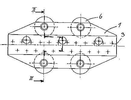
Figure 2 discloses a ground view of the carriage.
Figure 3 discloses a cross section along m-m in Figure 2.
Figure 4 discloses an overview of the arrangement of the
tenters.
DETAILED DESCRIPTION
The carriage 1 discloses four wheels or ball bearings 6, two
one each side, adapted for abutment against a guiding track in. the
longitudinal direction of the tenter. On top of the carriage 1 are arranged
inclined needles 3 which as known preferably are secured to an insert.
In the track of the tenter a chain (not shown) is running with carriers 2
catching the single carriages 1 and moving those along the track of the
tenter.
As disclosed especially in Figure 1 the carriage 1 is not
arranged above the carrier 2 with a fixed connection between the
carriage the carrier, but the carrier 2 is arranged between opposed pins 5
20 both of the which are biased with springs 4 which press against each
other opposed an abutment. The distance between two pins 5 when
situated against the abutments, corresponds substantially with the
diameter of the carriers 2. The characteristic of the springs 4 and further
properties are very exactly chosen in relation to the function to be
provided. The characteristics of the springs therefore may be different,
possibly one of the springs may completely be omitted.
The purpose of the springs 4 is to allow a displacement of
the carrier 2 in relation to the abutment in the carriage 1 on places along
.

- 4- 20866~6
the path of the product where the speed of the product and the speed of
the carrier are different.
This displacement should be possible substantially without
any stress on the product in the longitudinal direction. Seen in this
background it also is very clear that the properties of the spring 4 are
very important as the spring pressure should ensure that the rims of the
product is moved with the same speed as the rest of the product by
means of the carrier 2 which again is moved with a constant speed in the
longitudinal direction. The speed of the product, however, will not be
10 constant, but different substantially in different portions of the path.
The spring forces hereby should compensate the resulting
force from the friction force getting the ball bearings 6 component of the
tension force in the displacement direction of the product. This is
achieved by calculating the forces from measurements of the transversal
force as well as possible inclinement of the track in relation to the
displacement direction of the product.
The chain drive is controlled such that the tension in the
chain which substantially corresponds with the total spring forces, equals
the calculated resultant. The tension in the chain may be measured such
20 as by a loading cell in the suspension device of the chain drive motor.
With the tenters according to the present invention transversal forces are
laid on the rims of the fabric to maintain the tension uniformly in the
fabric, the transversal forces thereby moving simultaneously with the
fabric movement acceleration and retardation, due to the spring
connection between the needles in the rim, for which the speed varies,
and the chain having a constant speed.
lt6~
,~

Representative Drawing
A single figure which represents the drawing illustrating the invention.
Administrative Status

2024-08-01:As part of the Next Generation Patents (NGP) transition, the Canadian Patents Database (CPD) now contains a more detailed Event History, which replicates the Event Log of our new back-office solution.

Please note that "Inactive:" events refers to events no longer in use in our new back-office solution.

For a clearer understanding of the status of the application/patent presented on this page, the site Disclaimer , as well as the definitions for Patent , Event History , Maintenance Fee  and Payment History  should be consulted.

Event History

Description Date
Inactive: IPC from MCD 2006-03-11
Time Limit for Reversal Expired 1998-11-16
Letter Sent 1997-11-17
Grant by Issuance 1996-07-09
Request for Examination Requirements Determined Compliant 1993-12-03
All Requirements for Examination Determined Compliant 1993-12-03
Application Published (Open to Public Inspection) 1993-05-16

Abandonment History

There is no abandonment history.

Owners on Record

Note: Records showing the ownership history in alphabetical order.

Current Owners on Record
ABB ALFSEN & GUNDERSON AS
Past Owners on Record
BART T. BOON
HELGE KNUTZEN
KARSTEN T. NESET
Past Owners that do not appear in the "Owners on Record" listing will appear in other documentation within the application.
Documents

To view selected files, please enter reCAPTCHA code :


To view images, click a link in the Document Description column. To download the documents, select one or more checkboxes in the first column and then click the "Download Selected in PDF format (Zip Archive)" or the "Download Selected as Single PDF" button.

List of published and non-published patent-specific documents on the CPD .

If you have any difficulty accessing content, you can call the Client Service Centre at 1-866-997-1936 or send them an e-mail at CIPO Client Service Centre.


Document
Description 
Date
(yyyy-mm-dd) 
Number of pages   Size of Image (KB) 
Abstract 1993-12-10 1 21
Drawings 1993-12-10 1 29
Claims 1993-12-10 1 39
Description 1993-12-10 3 149
Description 1996-07-08 4 170
Abstract 1996-07-08 1 22
Claims 1996-07-08 2 66
Drawings 1996-07-08 1 30
Representative drawing 1999-02-10 1 9
Maintenance Fee Notice 1997-12-14 1 178
Fees 1995-10-31 1 41
Fees 1994-10-30 1 40
Fees 1996-12-03 1 26
Fees 1996-11-25 1 22
Fees 1996-10-20 1 49
Prosecution correspondence 1994-03-21 2 35
Prosecution correspondence 1993-12-05 1 19
PCT Correspondence 1996-05-01 1 34
Courtesy - Office Letter 1994-01-26 1 59