Language selection

Search

Patent 2086732 Summary

Third-party information liability

Some of the information on this Web page has been provided by external sources. The Government of Canada is not responsible for the accuracy, reliability or currency of the information supplied by external sources. Users wishing to rely upon this information should consult directly with the source of the information. Content provided by external sources is not subject to official languages, privacy and accessibility requirements.

Claims and Abstract availability

Any discrepancies in the text and image of the Claims and Abstract are due to differing posting times. Text of the Claims and Abstract are posted:

  • At the time the application is open to public inspection;
  • At the time of issue of the patent (grant).
(12) Patent Application: (11) CA 2086732
(54) English Title: METHOD OF MANUFACTURING A KNIFE BLADE
(54) French Title: METHODE DE FABRICATION D'UNE LAME DE COUTEAU
Status: Deemed Abandoned and Beyond the Period of Reinstatement - Pending Response to Notice of Disregarded Communication
Bibliographic Data
(51) International Patent Classification (IPC):
  • B26B 9/00 (2006.01)
  • B21D 53/64 (2006.01)
(72) Inventors :
  • COPPIER, MICHEL (France)
(73) Owners :
  • SEB S.A.
(71) Applicants :
  • SEB S.A. (France)
(74) Agent: SMART & BIGGAR LP
(74) Associate agent:
(45) Issued:
(22) Filed Date: 1993-01-05
(41) Open to Public Inspection: 1993-07-09
Availability of licence: N/A
Dedicated to the Public: N/A
(25) Language of filing: English

Patent Cooperation Treaty (PCT): No

(30) Application Priority Data:
Application No. Country/Territory Date
92 00128 (France) 1992-01-08

Abstracts

English Abstract


ABSTRACT
"Method of manufacturing a knife blade"
(Invention by Michel COPPIER)
The method of manufacturing the knife blade (1),
comprises the following steps.
by stamping the two faces (1a, 1b) of a blade
blank (1), a series of protuberances (2, 3) are formed,
extending transversely to the length of the blade and,
during the same stamping operation,
a chamfer is formed on one of the longitudinal
edges of the blade, after which,
said edge (5) of the blade opposite the chamfer
is sharpened.
Use especially in order to avoid the blade
sticking when cutting food.
(See Figure 1).


Claims

Note: Claims are shown in the official language in which they were submitted.

CLAIMS
1. A method of manufacturing a knife blade,
comprising the following steps:
by stamping the two faces (1a, 1b) of a blade
blank (1), a series of protuberances (2, 3) are formed,
extending transversely to the length of the blade and,
during the same stamping operation,
parallel to one of the longitudinal edges of the
blade, on both faces of the latter, two protruding ridges
(6, 7) are formed, arranged in the extension of the
vertex of the protuberances (2, 3) and a chamfer (4) is
formed, at least between one of these ridges (6, 7) and
the longitudinal edge of the blade, after which,
said edge of the blade is sharpened.
2. The method as claimed in claim 1, wherein the
sharpening burr formed on the cutting edge (8) of the
blade is removed by chemical polishing.
3. The method as claimed in one of claims 1 or 2,
wherein the sharpening which is carried out on the edge
opposite the chamfer (4) creates a chamfer (5) which is
symmetric or non-symmetric with the stamped chamfer (4).
4. The method as claimed in one of claims 1 to 3
wherein the protuberances (2, 3) are constituted by
elongated, parallel raised sections whose ends and
vertical are rounded.
5. The method as claimed in claim 4, wherein the
elongated raised sections (2, 3) extend in a direction
forming a certain angle with the length of the blade.
6. The method as claimed in claim 5, wherein the
- 6 -

ends of the elongated raised sections (2, 3) adjacent to
the cutting edge (5) of the blade are further from the
pointed end (9) of the blade than the other ends.
7. The method as claimed in one of claims 1 to 6,
wherein said protuberances (2, 3) or raised sections and
said chamfer are formed by cold forging.
8. The method as claimed in one of claims 1 to 7,
wherein, during stamping of the blank, two symmetric or
non-symmetric chamfers are created between the two ridges
(6, 7) and the longitudinal edge of the blade.
- 7 -

Description

Note: Descriptions are shown in the official language in which they were submitted.


2~ l3~
Method of manufacturing a knife blade.
FIELD OF THE INVEN~ION
The present invention relates ~o a method of
manufacturing a knife blade by stamping a steel blade
blank.
SUMMARY OF TH~ INVENTION
The aim of the present invention is to create a
knife blade making it possible to limit the cutting
forces by reducing the sticking of the food to the
la~eral faces of the knife blade.
According to the invention, this method is
charactarized by the following teps:
b~ stamping the two faces of a blade blank, a
serie~ o protuberances are formed, extending tran~-
versely to the length of the blade and, during the samestamping operation,
parallel to one of the longitudinal edges of the
blade, on both face3 of thQ latterl two protruding ridges
ar~ formed, arranged in the extension of the vertex of
-- 1 --

2 0 8 ~ 7 3 r ~
the protuberance~ and a chamfer is formed, at leas~
between one of these edge~ and the longitudinal edge of
the blade, after which,
said edge of the blade is sharpened.
The protuberances formed on the opposite faces of
the blade make it possible to reduca friction with the
food, when cut~ing, and consequentl~ to limit the ~orces
required from the user. In particulax, the~e
protuberances make it possible to limit sticking between
the food, especially fatty food, and the lateral faces of
the blade.
~ oreover, the stamping creates a chamer on one
of the longitudinal edges of the blade which simplifies
sharpening, since it i~ sufficien~ to sharpen the blade
opposite the chamfer.
Other features and advantages of the invention
will further appear in the description below.
BRIEF DESCRIPTION OF THE DRA~ING5
In the attached drawings, given by way of non-
limiting examples:
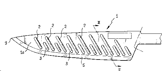
- Figure 1 is a plan view of one of the faces of
a kni~e blade obtained according to the method in accor-
dance with the invention;
- Figure 2 is a sectional view along the plane
II-II of Figure l;
- Figure 3 is a view similar to Figure 2, after
sharpening the edge of the blade opposite the chamfer.
DESCRIPTION OF THE PREFERRED EMBODINENT
The mathod of manufacturing the knife blade 1

3.~
repxeYen~ed in Figure 1, compri~es the following stepss
by stamping the two faces la, lb (see Figure 2)
of a blade blank 1, a series of protuberances 2, 3 are
formed, extending trans~ersely to the length of the blade
S 1 and, during the 3ame stamping operation,
parallel to one of the longitudinal ~dges of the
blade, on both faces of the latter, two protruding ridges
6, 7 are formed, arranged in the extension o ~he vertex
o~ the protuberances 2, 3 and a chamfer ~ is formed, at
least bet~een one of these ridges 6, 7 and the
longitudinal edge of the blade, after which,
said edga of the blade is sharpened (see Figure
3). The sharpened part is designated by the reference 5.
In Figure 2 it is seen that after the stamping
lS operation, the ~hickest part of the longitudinal edge of
the blade 1 adjacent to the chamfer 4 is delLmited by two
ridges 6, 7 which are situated on the two opposite face~
of the blade and arranged in the extension of the
vertices of the protuberances2formed on these two faces.
Moreover~ the sharpening burr formed on the
cutting edge 8 (sea Figure 33 of the blade 1 i~ removed
by chemical polishing.
The sharpening carried out on the edge opposite
the chamfer 4 creates a chamfex 5 which is symmetric or
non-symmetric with the stamped chamfer 4.
In the example represented in Figure 1, the
protuberances 2, 3 are constituted by elongated, parallel
raised sections whose end~ and vertice~ ara rounded.
Moreover, the elongated xaised section~ ~, 3

2~ 9J~
extend in a direction foxming a certain angle with ~e
length of the blade, which is such that the ends of the
elongated raised sectionR 2, 3 ad~acent to the cutting
edge 5 of the bladelare further from ths pointed end 9
S of the blade 1 than the other ends.
The protuberance~ or rai~ed section~ 2, 3 and the
chamfer 4 are preferably ormed by cold forging, under a
pres~ure of several tens of tons, between two matrices
whose surface reproduces the hollowe~-ou~ relief to be
ormed on the faces o~ the steel blank of the blade.
By way of non-limi~iny exampls, ~he width of the
pxotuberances 2, 3 lies between a few tens of millimeter~
and a few millimeters. The spacing between the pro-
tuberances 2, 3 i~ of the same order of magnitude.
Some protuberances 3 are shorter than the others
2, as indicated in Figure 1, in which the short pro~
tuberancss 3 lie between long protuberances 2.
~ he main advantages of the method which has just
been described are as follows: the whole of the blade is
produced in a single stamping operation and a single
sharpening operation.
The knife thus produced limits, by virtue of the
protuberance~ 2, 3, the sticking effects regardin~ food,
Qspecially atty food, and thus reduces the forces
reqùired from ~he users.
Needles to say, the invention is not limited to
the embodiment which ha~ ju~t been de~cribed and numerous
modifications may be applied to the latter without
departing from the scope of the invention.

7 ~ ~
Hence, according to a variant~ during ~tamping of
th~ blank, two symmetric or non-symmetric chamfer~ (see
dotted lines in Figure 2) are created between the two
ridges 6, 7 and the longitudinal edge of the blade.
-- 5 --

Representative Drawing
A single figure which represents the drawing illustrating the invention.
Administrative Status

2024-08-01:As part of the Next Generation Patents (NGP) transition, the Canadian Patents Database (CPD) now contains a more detailed Event History, which replicates the Event Log of our new back-office solution.

Please note that "Inactive:" events refers to events no longer in use in our new back-office solution.

For a clearer understanding of the status of the application/patent presented on this page, the site Disclaimer , as well as the definitions for Patent , Event History , Maintenance Fee  and Payment History  should be consulted.

Event History

Description Date
Inactive: IPC from MCD 2006-03-11
Time Limit for Reversal Expired 2001-01-05
Application Not Reinstated by Deadline 2001-01-05
Inactive: Status info is complete as of Log entry date 2000-02-21
Inactive: Abandon-RFE+Late fee unpaid-Correspondence sent 2000-01-05
Deemed Abandoned - Failure to Respond to Maintenance Fee Notice 2000-01-05
Application Published (Open to Public Inspection) 1993-07-09

Abandonment History

Abandonment Date Reason Reinstatement Date
2000-01-05

Maintenance Fee

The last payment was received on 1998-12-31

Note : If the full payment has not been received on or before the date indicated, a further fee may be required which may be one of the following

  • the reinstatement fee;
  • the late payment fee; or
  • additional fee to reverse deemed expiry.

Please refer to the CIPO Patent Fees web page to see all current fee amounts.

Fee History

Fee Type Anniversary Year Due Date Paid Date
MF (application, 5th anniv.) - standard 05 1998-01-05 1997-12-31
MF (application, 6th anniv.) - standard 06 1999-01-05 1998-12-31
Owners on Record

Note: Records showing the ownership history in alphabetical order.

Current Owners on Record
SEB S.A.
Past Owners on Record
MICHEL COPPIER
Past Owners that do not appear in the "Owners on Record" listing will appear in other documentation within the application.
Documents

To view selected files, please enter reCAPTCHA code :


To view images, click a link in the Document Description column. To download the documents, select one or more checkboxes in the first column and then click the "Download Selected in PDF format (Zip Archive)" or the "Download Selected as Single PDF" button.

List of published and non-published patent-specific documents on the CPD .

If you have any difficulty accessing content, you can call the Client Service Centre at 1-866-997-1936 or send them an e-mail at CIPO Client Service Centre.


Document
Description 
Date
(yyyy-mm-dd) 
Number of pages   Size of Image (KB) 
Abstract 1993-07-09 1 16
Cover Page 1993-07-09 1 14
Drawings 1993-07-09 2 33
Claims 1993-07-09 2 49
Descriptions 1993-07-09 5 133
Representative drawing 1998-09-10 1 13
Reminder - Request for Examination 1999-09-08 1 127
Courtesy - Abandonment Letter (Request for Examination) 2000-02-16 1 172
Courtesy - Abandonment Letter (Maintenance Fee) 2000-02-02 1 185
Fees 1997-01-03 1 38
Fees 1996-01-02 1 39
Fees 1995-01-03 1 33
Maintenance fee payment 1995-11-02 1 49
Maintenance fee payment 1994-11-10 1 50