Language selection

Search

Patent 2086797 Summary

Third-party information liability

Some of the information on this Web page has been provided by external sources. The Government of Canada is not responsible for the accuracy, reliability or currency of the information supplied by external sources. Users wishing to rely upon this information should consult directly with the source of the information. Content provided by external sources is not subject to official languages, privacy and accessibility requirements.

Claims and Abstract availability

Any discrepancies in the text and image of the Claims and Abstract are due to differing posting times. Text of the Claims and Abstract are posted:

  • At the time the application is open to public inspection;
  • At the time of issue of the patent (grant).
(12) Patent Application: (11) CA 2086797
(54) English Title: ACETABULAR CUP WITH SHIFTABLE ELEVATED RIM LINER
(54) French Title: CUPULE ACETABULAIRE AVEC REBORD MOBILE
Status: Deemed Abandoned and Beyond the Period of Reinstatement - Pending Response to Notice of Disregarded Communication
Bibliographic Data
(51) International Patent Classification (IPC):
  • A61F 2/34 (2006.01)
  • A61F 2/00 (2006.01)
  • A61F 2/32 (2006.01)
(72) Inventors :
  • BRODERICK, MELISSA A. (United States of America)
(73) Owners :
  • BRISTOL-MYERS SQUIBB COMPANY
(71) Applicants :
  • BRISTOL-MYERS SQUIBB COMPANY (United States of America)
(74) Agent: GOWLING WLG (CANADA) LLP
(74) Associate agent:
(45) Issued:
(22) Filed Date: 1993-01-06
(41) Open to Public Inspection: 1993-08-19
Availability of licence: N/A
Dedicated to the Public: N/A
(25) Language of filing: English

Patent Cooperation Treaty (PCT): No

(30) Application Priority Data:
Application No. Country/Territory Date
836,439 (United States of America) 1992-02-18

Abstracts

English Abstract


ACETABULAR CUP WITH SHIFTABLE
ELEVATED RIM LINER
ABSTRACT OF THE DISCLOSURE
The acetabular cup assembly of this invention includes
a bearing component having an elevated rim and a metal cup.
A groove is formed about the component for engagement with a
locking ring carried by the metal cup. The bearing component
may be inserted into the cup and tilted or tipped so that the
elevated rim is pressed downwardly against the rim of the
metal cup. In this position, the elevated portion of the rim
is out of the way of the surgeon permitting the head to be
more easily inserted into the bearing component. Once the
head is seated the surgeon presses against the raised lip of
the bearing component to shift the bearing component such that
the elevated lip is properly positioned. A snap ring locks
into a groove of the bearing component when positioned for
use.
Accordingly, it is an object of the invention to provide
a novel acetabular hip cup assembly.
Another object of the invention is to provide an
acetabular hip cup assembly wherein the bearing component may
be shifted to place the elevated lip in a generally parallel
relationship relative to the rim of the metal cup.


Claims

Note: Claims are shown in the official language in which they were submitted.

I CLAIM:
1 An acetabular hip cup assembly comprising a bearing
component and a cup component and means for
retaining said bearing component in said body, said
bearing component including a body with a
peripheral lip, said lip lying in two planes which
intersect one another at an angle such that a
portion of said lip being elevated when one portion
of said lip is positioned generally horizontal to
thereby define a elevated portion of said lip, said
cup component including a body terminating in an
annular lip and means carried, said bearing
component being shiftable between an unlocked
position and locked position, wherein with said
bearing component in said unlocked position, said
elevated portion of said lip is in contact with the
lip of the cup and said one portion of the lip is
spaced from said cup lip, in said locked position
said one portion of said bearing component lip
being in contact with said cup lip and said
elevated portion of said lip being spaced from said
cup lip with said retaining means being in locking
engagement with said bearing component and cup to
lock said bearing component against movement
relative to said cup.
2. The acetabular component of Claim 1 wherein said
retaining means includes a snap ring shiftably
carried within an annular groove in said cup body,
said bearing component body including an annular
groove for accommodating a portion of said snap
ring in an interference fit when said bearing
component is positioned in said locked position.

Description

Note: Descriptions are shown in the official language in which they were submitted.


-1- 2C8S797
ACETABULAR CUP WITH S~IFTABLE
ELEVATED RIM LINER
FIELD OF THE INVENTION
This invention relates to an acetabular cup having an
elevated rim liner which is shiftable to facilitate reduction
of the prosthetic hip joint.
BACKGROUND OF THE INVENTION
Prosthetic acetabular hip cup assemblies are well known
in the field of orthopaedic surgery. Acetabular hip cup
assemblies having elevated rims are also well known in the
art. Examples of prior art acetabular hip cup assemblies with
elevated rims and attached by snap rings are illustrated in
the following U.S. Patents:
Engelhardt, et al. - 5,049,158 discloses an acetabular
cup assembly having a bearing component and a metal acetabular
cup component held in a locked relationship by a wire formed
about the periphery of the bearing component. The bearing
component includes an elevated rim which contacts the rim of
the metal cup.
Forte, et al. - 4,695,282 disclosed an acetabular cup
assembly having a bearing component and a metal cup. The
bearing component may be temporarily positioned within the cup
prior to locking engagement to permit the surgeon to check the
orientation of the cup and bearing component. To lock the two
components together, the bearing component is pressed further
into the cup wherein a locking ring engages the cup. When
locked, the elevated rim of the bearing component contacts
the rim of the cup.
Parchinski - 4,650,491 discloses an acetabular cup
assembly wherein the bearing component includes a plurality
of rings which engage a groove in the metal cup to lock the
two components together. In use the elevated rim of the
bearing component contacts the rim of the metal cup.
During a procedure to implant the prosthetic acetabulum
and hip stem, to reduce the joint the surgeon must negotiate

-2- ZC~797
around the elevated rim to seat the femoral head within the
bearing component.
SUMMARY OF THE INVENTION
The acetabular cup assembly of this invention includes
a bearing component having an elevated rim and a metal cup.
A groove is formed about the component for engagement with a
locking ring carried by the metal cup. The bearing component
may be inserted into the cup and tilted or tipped so that the
elevated rim is pressed downwardly against the rim of the
metal cup. In this position, the elevated portion of the rim
is out of the way of the surgeon permitting the head to be
more easily inserted into the bearing component. Once the
head is seated the surgeon presses against the raised lip of
the bearing component to shift the bearing component such that
the elevated lip is properly positioned. A snap ring locks
into a groove of the bearing component when positioned for
use.
Accordingly, it is an object of the invention to provide
a novel acetabular hip cup assembly.
Another object of the invention is to provide an
acetabular hip cup assembly wherein the bearing component may
be shifted to place the elevated lip in a generally parallel
relationship relative to the rim of the metal cup.
Another object of the invention is to provide a novel
acetabular hip cup assembly having a shiftable bearing
component.
Still other objects of the invention will become apparent
upon a reading of the following description taken with the
accompanying drawings.
BRIEF DESCRIPTION OF THE DRAWINGS
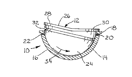
Fig. l is a side elevational view of the acetabular cup
assembly with the bearing component positioned to permit the
femoral head to be inserted into the bearing component.
Portions are sectioned for illustrative purposes.

_3_ 2C~797
Fig. 2 is the view of Fig. 1 with the bearing component
positioned for use.
DESCRIPTION OF THE PREFERRED EMBODIMENT
The preferred embodiment herein described is not intended
to be exhaustive or to limit the invention to the precise form
disclosed. Rather, it is chosen and described to best explain
the invention so that others skilled in the art might utilize
its teachings.
The acetabular hip cup assembly 10 of the invention is
illustrated in the figures as including a bearing component
12 and a metal cup component 14. The cup component 14
includes a hemispherical body 16 and a peripheral lip 18. An
internal groove 20 is formed within the cup adjacent the lip
18. A snap ring 22 is carried within groove 20. Bearing
component 12 includes a generally hemispherical body 24 and
a lip 26. As illustrated in the figures, lip 26 includes a
portion 28 which is generally parallel to lip 18 when the
bearing component is in the locked position of Fig. 2 and an
elevated portion 30 which is spaced from lip 18 when the
bearing component is in the locked position of Fig. 2. A
groove 32 is formed about body 24 adjacent lip 26.
In use, the metal cup is attached to the prepared
acetabulum by appropriate surgical techniques well known in
the art. The bearing component 12 is placed within the cup
14 as illustrated in Fig. 1 such that elevated lip portion 30
abuts lip 18 of the cup. As illustrated in Fig. 1, in this
position groove 32 is not aligned with ring 22. In this
position, a femoral head of a prosthetic hip stem (not shown)
may be seated in the bearing component by passing over the
elevated lip portion 30. Once the femoral head is properly
positioned within the bearing component, the surgeon pushes
against lip portion 28 to rotate the bearing component in the
direction of arrow 34 until lip 28 contacts lip 18 of the cup.
Snap ring 22 slides into groove 32 to lock the bearing
component to the metal cup component. In the locked position
of Fig. 2, elevated lip portion 30 is held at an angle
relative to lip 18 and is generally spaced therefrom.

_4- 2C~679~
It should be understood that once the two components are
locked together by snap ring 22, the intended use requires the
two components to remain fixed together.
3 It should also be understood that the invention is not
to be limited to the precise form disclosed above, but may be
modified within the scope of the appended claims.

Representative Drawing
A single figure which represents the drawing illustrating the invention.
Administrative Status

2024-08-01:As part of the Next Generation Patents (NGP) transition, the Canadian Patents Database (CPD) now contains a more detailed Event History, which replicates the Event Log of our new back-office solution.

Please note that "Inactive:" events refers to events no longer in use in our new back-office solution.

For a clearer understanding of the status of the application/patent presented on this page, the site Disclaimer , as well as the definitions for Patent , Event History , Maintenance Fee  and Payment History  should be consulted.

Event History

Description Date
Inactive: IPC from MCD 2006-03-11
Time Limit for Reversal Expired 1996-07-06
Application Not Reinstated by Deadline 1996-07-06
Deemed Abandoned - Failure to Respond to Maintenance Fee Notice 1996-01-08
Inactive: Adhoc Request Documented 1996-01-08
Application Published (Open to Public Inspection) 1993-08-19

Abandonment History

Abandonment Date Reason Reinstatement Date
1996-01-08
Owners on Record

Note: Records showing the ownership history in alphabetical order.

Current Owners on Record
BRISTOL-MYERS SQUIBB COMPANY
Past Owners on Record
MELISSA A. BRODERICK
Past Owners that do not appear in the "Owners on Record" listing will appear in other documentation within the application.
Documents

To view selected files, please enter reCAPTCHA code :


To view images, click a link in the Document Description column. To download the documents, select one or more checkboxes in the first column and then click the "Download Selected in PDF format (Zip Archive)" or the "Download Selected as Single PDF" button.

List of published and non-published patent-specific documents on the CPD .

If you have any difficulty accessing content, you can call the Client Service Centre at 1-866-997-1936 or send them an e-mail at CIPO Client Service Centre.


Document
Description 
Date
(yyyy-mm-dd) 
Number of pages   Size of Image (KB) 
Abstract 1993-08-19 1 27
Drawings 1993-08-19 1 16
Claims 1993-08-19 1 34
Cover Page 1993-08-19 1 13
Descriptions 1993-08-19 4 134
Representative drawing 1998-10-20 1 8
Fees 1994-12-22 1 48