Note: Descriptions are shown in the official language in which they were submitted.
WO 92/00684 2 0 8 6 9 3 4 pCr/F191/00217
Fastening devlce
The lnvention relates to a device for power exerting con-
nection to a flexible elongated pulling means. The device is
especially intended for fixing an attachment along the ex-
tension of a rope or a cord or the like in such a manner, that
the end portions of the rope or the cord need not be threaded
through any part of the device. The invention also relates to
a specific use of the device.
Several methods and devices are known for fixing ropes, cords
or the like to different objects, in order to make, in this
manner possible the exertion of power with or upon the rope.
Usually the methods comprise the forming of a more or less
strong and more or less complicated knot, so that different
loops of said rope will lock underlying loops, thus preventing
slipping.
Usually the tying of strong knots comprises threading one free
end of said rope or cord through loops or the like formations,
or around fixed obstacles. Difficulties, however, arise if one
wishes to fix an attachment along a rope the ends of which are
not for so~e reason free. Traditionally in such cases one has
used a loop of the rope, whioh loop then has been tied into a
suitable knot. Such knots are, however, never as strong as a
corresponding knot on a single rope, and therefore there is
always a risk for slipping, which in some cases may be fatal.
Another drawback with conventional knots is the fact, that
only few special knots are suitable for accommodating strong
forces in such a way that the knot may still be easily opened
after the rope or cord has once been stretched to its limits.
Various arrAngements have been developed in order to solve the
the above problem , in which arrangements a device is mechani-
- cally tightened to a rope or cord. In most such arrangements
: -. - . ..... -. .. - ~ . . - . -
, .. . . - .: .. . . .. . . . . : . .... . ; :
W092/006X4 PCT/F191/00217
2086934 2
the probiem remains that the rope or cord itself is lntended
to pass throu~h holes or apertures in the device, wn:ch thus
canr.o. be usec in cases where both ends of tne rope a-e fi~ed
o- for some othe- reason difficult so thread, due for example
to the rope length o- the end structure of the rope. ~~-ther,
special pulling devices have been developed for fixing a steel
wire or some other essentlally non-bending pulling means. Such
devices are, however, technically complicated and charge the
pulling means with teeth or the like means. US-patent
3,930,288 on the other hand discloses a complicated device for
the branching of ropes
Further, conventional cleats are known, at which a rope is
locked by winding it several times in loops located one upon
the other, moving it to and fro around a fixed pin or the like --
until the rope successively locks itself so that a reliable
attachment is achieved. The drawback with such a cleat is that
for a satisfactory function it needs a considerable amount of
rope. A conventional cleat device is further so designed that
it cannot be used in any suitable manner standing free from a
fixed structure.
The object of the present invention is to provide a fastening
device which can be fastened by simple manipulation at a near-
ly arbitrary position alor.g a rope or a cord. The device is
further such, that it works independently of whether it is
totally loose and free standing or is connected to a fixed
structure. The attachment of the pulling means, for example
the rope or the cord, is such that said attachment without
slipping will withstand a stress equal to the stress in the
rope itself but may and still thereafter be loosened by a
simple manipulation.
,
The characteristic features of the invention are indicated in
the attached claims. Thus the invention is characterized by
the device having at least three elements extending in dif- ,
ferent directions, said elements having contact surfaces at
. -: . .,. , ' . .' .:: ' " :
. ........ , . : ~ .
-. ' . ''
w092/00684 2 0 8 6 ~ 3 ~ PCT/F191/0~21~
whlch aa elongated pulling means is to be wound. The winding
proper is made so that a first loop of said pulling means runs
from one first essentially unstressed end thereoS along a
flrs. contact surface at a first leg of the device Thereafter
sald pulllng means runs over a second contact surface at a
second leg and behind an essentially pin like protrusion
having a third contact surface, in order to center the posi-
tion of a locked loop of said pulling means and a locking loop
positioned over said locked loop against said first contact
surface. Said first leg converges slightly towards an opposite
guiding- or straining surface at said second leg, so that said
pulling means with its extension at an essentially pulled end
located opposite to said first end f~nally forms a straining
loop, said loop being suitably wedged against said guiding- or
straining surface and extending over said first loop of said
pulling means, thus locking said first loop to said first
contact surface. An especially preferable use of the device
includes an arrangement wherein said fastening devices are
arranged at both ends of a flexible piece. Another preferred
embodiment comprises the use of the inventive device in con-
nection with articles of clothing or the like.
The invention will now be described with reference to the
attached drawing, where
Fig. 1 shows the general functional principle of the inventive
device,
Fig. 2 shows general applications in connection with a
resilient mooring or pulling device,
Fig. 3 shows an application as a handle to be attached to a
rope,
Fig. 4 shows a special embodiment of the inventive device,
applied as a general fixing point for ropes and cords,
Fig. 5 show a preferred embodiment of the invention in con-
nection with a resilient flexible piece,
Fig. 6 shows an especially preferred embodiment of the in-
vention in connection with a resilient flexible piece,
. .- . . - , . .. ~ .
- . . . ...
- . ~, , - ~ . .
,, ., . - . . - . : - . - - , : . .
- ~ . ,, ~ . .: . . . . ..
,
. - ~ . , ~ :
- : . -
W09~/006X4 I'CT/F191/00217
2086934 4
Fig. 7 shows a sectlon (A-A) of the device 1n Fig. 6,
Fig. 8 shows an alternatlve embodlment of the device accordlng
to Fig. 6, and
Figures 9A and 9B show ske.ched alternative emDoaimenes o- the
invention.
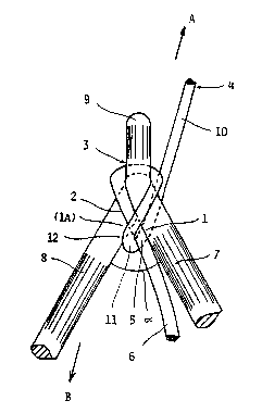
The device according to Figure 1 shows the invention in its
simplest form and comprises an essentially Y-shaped piece
having legs 7, 8 extending both in the same general direction
and positioned at an angle with respect to each other, said
device further comprising a tenon-like protrusion 9 extending
generally in the opposite direction. Legs 7 and 8, respective-
ly,-comprise surfaces 1, la, one of which acts as a contact
surface 1, depending on a~ which side said pulling means, for
example a rope 4, is laid. The corresponding surface la at
said second leg 8 acts as a guiding surface or suitably as a
straining surface i2, and, respectively, as said contact sur-
face when said rope 4 runs as a mirror-image of the case
indicated. Said first contact surface 1 at said first leg 7
will thus be located inclining transversely opposite in
relation to the general pulling direction A for said pulling
means 4, said first contact surface 1 being set at an angle a
against said second leg 8.
The locked portion 5 of rope 4 abuts said contact surface 1
under a loop 11, which, when said rope is guided correctly,
comprises a direct extension of that rope end 10, where the
actual power exertion takes place during a haul. A haul in the
rope end 10 will make said loop 11 strain harder against the
end 6 and its loop 5, which under said loop 11 will be harder
strained against said contact surface 1 thus being locked.
Since said leg 7 converges against said straininq surface 12
of said second leg 8 said loop 11 simultaneously will be
wedged in between said loop 5 and said straining surface 12,
so that said loop 11 will not open up even if said rope 4
possibly were to slack off.
: .. . .. : ... .
-, -, : - ,, .~ . : .
.. . . . . .. . . .
- : . ~. . ..
: ' ~,, . . i ., .,~, .. .
.. ..
W092/00684 2 0 8 6 9 3 4 Pcr/FI9l/oo2l7
In order to improve the locking said contact surfaces 1, la,
and 3, respectively, as well as said corresponding straining
s~-~ace 12 may comprlse suitably incllned knurled formations
or a corresponding coarse surface structure for increasing the
fr;ction
For the devlce to have the fasteninq effect desired it ls
essential, that the rope 4 at a pull presses said loop 5
strongly against said contact surface 1. In the embodiment
shown in Figure 1 this is achieved thereby, that the rope 4
runs from said end 10 in a loop 11 over said end 6 and its
loop 5 and over said first leg 7 and back in essentially the
same direction, so that said loop 11 will have a generally
U-shaped run For this purpose said rope is placed aroun~ a
tenon-like guiding protrusion 9, which is essential for the
invention, behind which protrusion said rope rests against a
contact surface 3 after which it runs back over said leg 8
having an upper contact surface 2, in order to finally form
said locked loop 5 of said free end 6. For the invention it
is, in this case, unessential how said free end 6 continues,
and said end may e.g. be completely loose or fastened to
another structure, or, as is indicated more clearly in Figure
2, to a corresponding device directed into the opposite
direction.
According to the invention the rope proper may be wound around
the device in essentially two different manners. A secure
manner, which may be utilized independently of said legs 7, 8
being, at their opposite ends, open or possibly closed into a
shape shown e.g. in Figures 2, 3, 5...9, comprises the steps
of bringing a loop of the rope 4 in between said legs 7, 8,
turning said loop half a turn, and threading said loop over
said tenon-like protrusion 9. Said protrusion 9 centers then
the position of said rope with respect to said legs 7 8, so
that a locking may be achieved. Thereafter the rope 4 is
stressed. Due to the structure of the device, said tenon-like
protrusion 9 having a circumference smaller than the ciFcum-
.. , ., .:.. .. ~ : . -
. . - - - ~ :: ~ . - : ~ .
-:. : - . . .
:
- - - : . :
W092/0068~ I'CT/F191/00217
2086934 6
ference formed a_ound both legs 7, 8 and the angle between
them, the rope 4 and especiallv its loops 5 and 1I wil' slide
a ~ ~, when exposed to s~ress, and thereafte- they w''l auto-
ma~1cally, due to the guiding inf'uence of sa~ protrusior. 9,
.ake a posltion where sa d loop 5 a~ the non-pulled enc 6 will
be locked betwee~ said contacl surface 1 ae said les 7 and
said pulled loop 11, whlch itself then will be locked between
sald loop 5 and said straining surface 12.
For said reasons it is preferred that said tenon-like pro-
trusion 9 extends from a point located outside the area which
is defined by the (geometrical) projection of said open angle
a between said legs 7, 8, and favorably so, that the circum-
ference of said protrusion 9 at its base is smaller than all
circumferences formed around both legs and said angle a in the
area of said angle.
An alternative way to achieve the desired twist in the rope is
holding the more free end 6 essentially along one leg 7, and
thereafter twisting said rope over said contact surface at the
other leg 8, up over contact surface 3 behind said tenon-like ~:
protrusion 9 and back over said more free end 6 and its loop
5. Laying the rope this way automatically brings about said
U-shaped loop 11 locking said loop 5 of said rope end 6 at
said contact surface 1, when a pulling force is exerted at
said pulled end 10 in the general pulling direction indicated
A. This way of twisting automatically brings said loops 5 and
11 into correct positions at the bottom of said angle a
between said legs 7 and 8.
The exact position for loops 5 and 11 may not be absolutely
critical for the function, but it is still appropriate to
locate the loops as deep into the botto~ of said angle a as
the rope thickness permits. Thus a certain locking o' said
U-shaped loop 11 is achieved by said loop abutting said con-
tact surface 2 of said second leg 8, before it becomes wedged
n between said stressing surface 12 and said loop 5 for
- .: . , ;~, . . ;. . ':; ,- -
: ~-. . : , .. ,. . ,~
.. : - ; :: ~ :
:, - :: . . ::
-~ : : ". - ~ ' , .
, : .: ~ :: , , . :
.. : . : : : . . ; , : .
. .
W092/006~4 ~ 0 8 6 9 3 ~ rcT/FI91/002l7
locking said loop 5. In order to secure the locklng also in
cases when no pulling power acts upon the rope 4 lt is
app~opriate, that the acute angle ~ between said legs, and
es~eciall~ between thei- opposlte consact s~ aces, is Or the
orce- 30...14-- Fo- man~ rope eypes an 2r.~1e of the order
45...70 has proved tO be especially effectlve, while other
rope types and applications well permit an angle up to 120-
wlthout any reduction in the firmness. This applies especially
for the area where said loops 5, 11 of said pulling means will
be located after said twisting, i.e. where the distance
between said legs 7, 8 is less or equal to twice the diameter
of said pulling means 4.
_ . .. . .
For certain embodiments said angle a between said legs may
even be essentially constituted by said legs extending from a
generally rounded base surface, where said leg angle is nearly
180-, whereafter said legs gradually turn`towards each other.
This embodiment is especially suitable for certain rope types
and in cases, where easy unlocking is more important than the
durability of the locking during repeated slackenings of the
pulled end 10 of said rope. Examples of such embodiments
appear in Figures 8 and 9A. At said embodiments an essentially
acute angle is normally formed for stout ropes 4 between on
one hand a respective leg 7, 8 and on the other that rope loop
5, which already butts against the respective other leg 8, 7.
A stout rope will thus be pressed in between one leg on one
hand and that rope portion which lies close to the other leg,
on the other hand, so that a locking i6 achieved. If the rope
is so slender, that a locking in the described manner cannot
be achieved, sald protrusion 9 will in any case center said
free end 6 and said loop 11 in such a mutual manner, that said
loop 5 at said free end 6 will always be located under said
pulled loop 11 and thus it will be pressed against said con-
tact surface 1 at one of said respective legs 7, 8. Said con-
tact surface 1 will normally be located somewhat higher up
alQng the periphery of the leg (when seen from the bottom
portion of said angle ~), and sometimes the contact surface in
.. . . ~ .: - . ,. . , . . . . - , .
: : - . . . :
.. . . . .
W092/00684 l'CT/FI91/00217
208~934 8
these embodlments will be located near the plane, which is
formed by the outermost surfaces of said legs 7, 8 and said
tenon-like pro~rusion 9. In this way a locklng will be
achleved, which usuall~ suf r- cien., especiallv in appli-
cat:ons wnere .ne pu'~ s cor.tinuous, or whe~e an unlocklng
does noe resuls in an~ considerable disadvantage.
For certain types of especially sllppery ropes it is
approprlate to arrange, at one or more contact surfaces,
special means for gulding the position of said rope in
relation to the respective contact surface. Such means may com-
prise notches for the rope or beads or the like projections
for guiding said rope. Figure 4 shows such a very favourable
alternative embodiment of the invention, the device comprising
an auxiliary tenon, i.e. a second tenon-like protrusion 15,
which actively guides the loop 11 at the pulled end 10 of said
rope 4, in relation to the essentially unloaded end 6. In this
embodiment said tenon-like protrusion 15 divides said angle a
into two parts, so that said essentially unloaded end 6 of
said rope 4 is forced to run on one side of said protrusion
lS, while said loaded end 10 runs on the other side of the
protrusion 15 between the protrusion and said second leg 8. In
this case loops 5 and 11, respectively, at said ends will
cross each other at the base of said second protrusion 15, and
said contact surface 1 will consequently be located upon the
device at the common base portion of said leg 7 and said pro-
trusion 15. This embodiment is especially advantageous in
cases where the load on said rope end 10 may vary considerably
in force and direction, since said second tenon-like pro-
trusion 15 will define a locking contact surface 1 exactly
while at the same time achieving an effectively wedged locking
of said loop 11 between said protrusion 15 and said strain
surface 12 at said second leg 8. In this embodiment both
partial angles ~ 2, i. e. the angle between said second
protrusion 15 and the respective leg 7, 8, are suitably of an
equal order of magnitude (30...75 ) as said ea~lier mentioned
angle ~ between said legs 7, 8. Usually it is appropriate that
, ~ . , . ., ~
, .
.
, ,.
w092/00684 2 0 8 6 9 3 4 PCT/F191/00217
both partiat angles ~ and ~2 are essentially equal, so that
the twlstlng ~irection for sai~ pulling means 4 need not be
chosen ln advance. In certain special cases said partial
angles may be of different magnitude, which for certain
specl21 types Or rope gives a better hold, a' the expense of
the dev~ce's '~two-sided" function.
As lndicated above the tenon-like protrusion 9 is of essential
importance for the device's function. Said tenon-like pro-
trusion 9 extends suitably from a point located outside an
area defined by the open angle a between said legs 7, 8. The
length of said protrusion, determined from said point, should
be at least 2 times the diameter of said pulling means 4, in
order to prevent said loop behind said protrusion 9 and its
contact surface 3 from moving up over said protrusion 9 at any
momentary slackening of said pulling means 4. Such a movement
would immediately decompose the whole arrangement, and there-
fore it is appropriate, that said tenon-like protrusion 9 has
a diameter of 3...6 times, in some special loosely laid appli-
cation even 10 times the diameter of said pulling means 4. In
a special embodiment of the invention said decomposition of
the arrangement is utilized so that said tenon-like protrusion
9 is arranged to be bending or retractable behind a lock which
prevents unvoluntary opening.
In order to achieve a self-tightening function the circum-
ference of said tenon-like protrusion 9 at its base is
suitably less than all those circumferences found around both
legs and said angle in the area of said angle a. In this way
said pulling means 4 will always, when stressed, slide auto-
matically into position until said pulling means 4 is located
around the base of said tenon-like protrusion 9 resting
against its contact surface 3.
.
The general working principles of the invention have been
explained above. The special embodiments of the invention
comprise several applications, where in said first leg 7 com-
.
., . .. . :
... - . , ... ~ . . . - - ~ : -
., ~ . - .. . .
'. ' ` ' ~, - '. '. ,- ' '"'. .. , ' , " : ~ : ' :
- . . : ' :. . .: . . - . ' ' ''- : .
.. '. ' :: ' ,~, . : : . :
W092/00684 PCr/Fl9l/00217
~6934 lO
prises a shorter portion, whereby the real power exertlon will
take place via said second leg 8 In certain other appli-
cations said first and second legs 7, 8 are connected to each
other also outside said area comprising said contact su-faces
1, 2, 3, i.e outside the area where said pulling device 4
wil' be locked to the device Thus Figure 2 shows an appli-
cation especially designed for marine conditions. In thls
application, showing an examples of two different embodiments
of the invention, said legs 7, 8 constitute a closed ring 16,
which in the shown embodiment further may be opened th_ough a
locklng nut 17 in accordance with known shackles. In contrast
to known shackles both devices according to Figure 2 may
easily be fastened to an arbitrary ~point along a rope without
requiring access to any free rope end.
In the embodiment shown in Figure 2 there are two such
devices, one of which by way of an example further comprises a
second tenon-like protrusion 15, according to the invention
connected each to its own end of an elastic band 18 or the
like. Thus an elastic mooring device is achieved, which device
may be fixed to any point along a mooring rope for e.g. small
vessels, although said rope is already applied and fastened.
The same arrangement may advantageously be used in the towing
of vehicles, whereby an especially smooth and jerk free move-
ment is achieved even if the drivers should happen to be un-
experienced. Another embodiment comprises several devices
connected to each other, said arrangement being applicable for
branching ropes to different directions e.g. for fixing a load
to a platform.
A further embodiment of the invention comprises a handle as
8hown in Figure 3. Such a handle comprises two legs 7, 8
interconnected by a suitably transverse pulling bar 19 and it
can be used for a variation of purposes when one wishes to
obtain a firm grip on a rope or a cord. Such a handle has
further the advantage, that the device can be easily moved
along a rope not yet under strain, while a strain locks said
~........................ . . -.
- : . . - . ~ ~ . - . : -
.
. . : : . ., :
- , ~.: : - ' . ~'. ' .
w092/006x4 2 0 8 6 9 3 4 PCTtF191/00217
1 1
handle to sald rope n a secure manner.
Sald pulling bar 19 b~tween sald legs 7, 8 may also be ~onstl-
tuted by a more or less rigid structure, e.g. the frame o~ a
vehicle, and the device according to the invention is
especially well suitable for occasional towing of vehicles. By
using the invention ln both the towing and the towed vehicle a
secure fastening of the tow rope is obtained, in a way that
absolutely holds durlng the actual operation and which there-
after may be easily disconnected after the towing despite a
heavy load. In an advantageous embodiment of the invention the
device comprises one or more suitably pointed recesses 21 (see
e.g. Figure 3) arranged for example in a customary trailer
hitch for light trailers. A usual h~ul stud with an affixed
ball may thus temporarily work as said tenon-like protrusion
9. For the function of the invention it is not absolutely
necessary that said protrusion extends in the same level as
said legs 7 and 8, even though such an arrangement usually is
preferable for simple handling.
In order to further secure the locking it may in some embodi-
ments be appropriate that one or both legs 7, 8 further com-
prises special locking -means preventing said rope 4 and its
locking loop ll from moving freely. Said locking means
favorably comprise means movable along a respective leg 7, 8,
suitably rings or tubes of plastic or the like elastic fric-
tional material, which means are pressed against said loops 5,
ll, when one wishes to safeguard oneself against the risk,
that a slackening of the strained rope end lO will lead to the
twisted portion unfixing itself. Alternatively said locking
means may comprise one or several pieces of elastic frictional
material applied wholly or partially over said open angle a
between said legs 7, 8. Such pieces then comprise one or
several slots into which said rope 4 and its loops 5, ll may
~e introduced under frictional impact each from its side,
finally to form the desired twist. A U-shaped rope loop ll
locked in this manner cannot get out of position even if said
. ~ . .
,, .. .... , ,.~, ., ~ . . ~ ........................ , :
,, - . . ~, . . . , . .. , ~" - ~ -: .. : ,, , . ,: , . ; " . . :: . . .
W092/00684 ~,33 ~ 12 rCT/Fl91/002l7
rope end 10 were to slacken completely, and when said rope
again comes under strain it will automatically assume a posi-
tion where a straln over said loop 5 is present.
Especially advantageous embodiments are shown in Figures 5, 6
and 7. All of these concern devices, wherein the invention is
used in connection with an elastic band or the like flexible
piece, in order to allow a resilient mooring of boats, towing
of vehicles and the like fields of application. Thus figure 5
shows in greater detail how a flexible band 18 su,tably of a
generally flat nature comprises a transverse beam-like portion
23. Said flexible band 18 and said beam-like portion 23
suitably comprlse reinforcement bands or the like, which are
mould into said flexible material in the joint between band
and beam. The width of said flexible band 18 is equal to or
preferably slightly exceeds the distance between essentially
parallel extensions 24, 24a of said legs 7, 8. Said extensions
24, 24a run in a parallel curve over said transverse beam 23
of said flexible band 18, and thereafter they are joined under
said band 18. The arrangement shown in Figure 5 gives a firm
and tearproof fastening for said flexible band 18 at the con-
necting device, and at the same time said band 18 may easily
be replaced by twisting said band around its longitudinal
axle, so that said transverse beam 23 is disengaged from the
curved portion of said extensions 24, 24a.
The device according to Figures 6 and 7 show a further appli-
cation of the invention in connection with a resilient
flexible piece. Here the flexible piece 18 itself in each of
its ends (for clarity only one end portion of said piece is
shown) is designed so, that an opening 25 is consti~uted in
the respective end, said opening being surrounded by ex-
ten8ions 24 and ending up with legs 7 and 8, from which said
tenon-like protrusion 9 emanates. In said Figures a phantom
line indicates, that the embodiment also may comprise a
central protrusion 15, which is directed into said opening 25.
Said tenon-like protrusion 9 comprises at its end suitably a
, . - , .. , . . . , , :
- - , ' . ,. ' ~
- .
:: :
: . . ~ , ., ; .-, ....... . :
- , : .. . ~ . : ~ -
: - : : .
~b~4
W092/00684 rCT/F191/00217
13
thlcke_ por~_~on 2~ ~reventing said elongated pull1ng means
fro~ eeiv s'i~ing over sa;d protrusion a, The device itself
is s~ tab'y made of a resilient flexible materlal, e.~. rubber
o- t:s~ like. T n order to lmprove the ressstance to tearing of
the ' ex~ble materlal tne device accordsng to thls embodlment
suitabiy comprises, at its ends, relnforcement means 27 made
e.g. of thread or bar like material of metal, plastics or of a
flexible fiber material. These reinforcement means preferably
run within the flexible basic material, at least around said
o~enin~ 25 anc inside said tenon~ e protrusion 9.
Fsgure 9A and 9~ show dlfferent alternatlve sketches of an
alt~rnatlve embodlment of tne lnventlon, where the speclflc
connectlng devlce ln accordance with the lnvention applies to
a buckle to be used in clothing. The sketches show alternative
buckles which as such may be used to button up e.g. a doffel
coat, for lacing shoes, as a lock for knapsacks, bags or the
like, or which works as a buckle for a girdle or the like. In
the shown applications said buckle works in accordance with
the inventive principles described above, while the buckle's
artistic design of course may vary considerably according to
the fashion and application demands. The shown embodiments
should be regarded as examples only. Further it is evident for
the average expert, that the invention within the scope
- defined in the claims may find applications in a great variety
of fields wherein a ductile or flexible elongated element
shall be connected to a buckle or the like element of
essentially solid structure, said element being more or less
fixedly mounted or alternatively attached to a corresponding
flexible or resilient means.
. -,
.. . . . . . . . .
. - . . . .
..