Language selection

Search

Patent 2087332 Summary

Third-party information liability

Some of the information on this Web page has been provided by external sources. The Government of Canada is not responsible for the accuracy, reliability or currency of the information supplied by external sources. Users wishing to rely upon this information should consult directly with the source of the information. Content provided by external sources is not subject to official languages, privacy and accessibility requirements.

Claims and Abstract availability

Any discrepancies in the text and image of the Claims and Abstract are due to differing posting times. Text of the Claims and Abstract are posted:

  • At the time the application is open to public inspection;
  • At the time of issue of the patent (grant).
(12) Patent Application: (11) CA 2087332
(54) English Title: BLADE COLLET
(54) French Title: DISPOSITIF DE SERRAGE POUR LAME CHIRURGICALE
Status: Deemed Abandoned and Beyond the Period of Reinstatement - Pending Response to Notice of Disregarded Communication
Bibliographic Data
(51) International Patent Classification (IPC):
  • A61B 17/14 (2006.01)
  • B23D 51/10 (2006.01)
(72) Inventors :
  • PASCALOFF, JOHN HENRY (United States of America)
(73) Owners :
  • LINVATEC CORPORATION
(71) Applicants :
  • LINVATEC CORPORATION (United States of America)
(74) Agent: GOWLING WLG (CANADA) LLP
(74) Associate agent:
(45) Issued:
(22) Filed Date: 1993-01-14
(41) Open to Public Inspection: 1993-07-28
Examination requested: 2000-01-07
Availability of licence: N/A
Dedicated to the Public: N/A
(25) Language of filing: English

Patent Cooperation Treaty (PCT): No

(30) Application Priority Data:
Application No. Country/Territory Date
826,341 (United States of America) 1992-01-27

Abstracts

English Abstract


ABSTRACT OF THE DISCLOSURE
A collet for attaching a blade to a surgical saw is
biased toward a closed position in which the blade is securely
clamped between a drive member and a clamping member. A
rotational movement of a knob is converted into a
translational movement of the clamp to open the collet. A
mechanism is provided for maintaining the collet in the open
position for simplified operation and cleaning.


Claims

Note: Claims are shown in the official language in which they were submitted.

-5-
CLAIMS
I claim:
1. A collet for attaching a blade to a surgical instrument
having a source of power, the collet comprising;
a housing having an axis,
a first member mounted in the housing for transmitting
power from said source of power to said blade, the
first member including a first clamping surface
perpendicular to the axis,
a second member mounted adjacent the first member, the
second member including a second clamping surface
perpendicular to the axis, the second member being
movable along the axis between a closed position
wherein the second clamping surface is proximate
the first clamping surface and an open position
wherein the surfaces are separated,
a third member rotatably mounted to the housing,
a means for moving the second member between the open
and closed positions in response to a rotation of
the third member.
2. The collet of claim 1 further comprising a spring biasing
means for biasing the second member toward the closed
position,
3. The collet of claim 1 wherein the means for moving the
second member comprises a grooved retainer having a helical
groove, the grooved retainer being fixedly attached to the
housing, and a fourth member linking the second member to the
helical groove such that as the forth member moves along the
helical groove the second member moves between the open and
closed positions.
4. The collet of claim 3 wherein the fourth member comprises
a ball.

-6-
5. The collet of claim 4 further comprising a means for
locking the second member in the open position.
6. The collet of claim 5 wherein the means for locking the
second member in the open position includes a detent formed
in the helical groove in which the ball may be disposed.
7. A collet for attaching a blade to a surgical instrument
having a source of power, the collet comprising;
a housing having an axis;
a blade shaft mounted in the housing for transmitting
power from said source of power to said blade, the
blade shaft including a first clamping surface
perpendicular to the axis,
a blade clamp mounted in the housing for movement
parallel to the axis, the blade clamp including a
second clamping surface perpendicular to the axis,
the blade clamp being movable between a closed
position wherein the second clamping surface is
adjacent the first clamping surface and an open
position in which the second clamping surface is
spaced from the first clamping surface,
a spring biasing the blade clamp toward the open
position,
a means responsive to a rotational input for moving the
blade clamp between the open and closed positions.
8. The collet of claim 7 wherein the means for moving the
blade clamp comprises a grooved retainer having a helical
groove and a ball linking the blade clamp to the helical
groove such that as the ball moves along the helical groove
the blade clamp moves between the open and closed positions.
9. The collet of claim 8 wherein the grooved retainer has
a detent formed at an end of the helical groove, the ball
being positionable in the detent to maintain the blade clamp
in a fixed position.

-7-
10. A collet for attaching a blade to a surgical instrument
having a source of power, the collet comprising;
a housing having an axis;
a hollow blade shaft mounted in the housing for
transmitting power from said source of power to
said blade, the blade shaft including a first
clamping surface perpendicular to the axis for
contacting said blade;
a drive pin connected to and extending from the first
clamping surface parallel to the axis, the pin
being engageable with said blade;
a blade clamp including a blade clamp shaft disposed for
axial movement within the hollow blade shaft
between a first position and a second position and
a second clamping surface perpendicular to the
axis, the second clamping surface having an opening
aligned with the pin to receive the pin when the
blade shaft is in the second position;
a main spring disposed around the blade clamp shaft for
biasing the second clamping surface toward the
first clamping surface;
a grooved retainer fixedly attached to the housing, the
grooved retainer defining a hollow cylinder
parallel with the axis and with a wall, the grooved
retainer having a helical groove forming an opening
along the wall with a first detent at an end of the
groove and a second detent at another end of the
groove;
a plunger disposed for axial movement within the grooved
retainer, the plunger being adjacent an end of the
blade clamp opposite the second clamping surface,
the plunger having an annular groove;
a hollow knob rotatably attached to the grooved
retainer, the knob defining an inner wall adjacent
the helical groove, the knob having a vertical
groove formed in the inner wall parallel to the
axis;
a conical spring disposed within the knob for biasing
the plunger away from the knob; and

-8-
a ball disposed within the vertical groove, the ball
protruding from the vertical groove into the
helical groove and also into the annular groove
such that rotational movement of the knob propels
the ball along the helical groove thus causing the
plunger and likewise the blade clamp to move along
the axis, the ball being positionable in the first
detent wherein it is stably held due to force
exerted by the main spring and the ball being
positionable in the second detent wherein it is
stably held due to force exerted by the conical
spring.

Description

Note: Descriptions are shown in the official language in which they were submitted.


V (J ~ J f
_ADE COLLET
B~C~GROUND OF THE INVE.N'l`ION
The present invention relates to blade attachment
mechanisms for surgical saws.
Typical blade collets utilize a threaded stud extending
from a drive mechanism and a nut engaging the stud to clamp
the blade to the drive mechanism. These collets generally
require the use of a separate wrench to turn the clamping nut.
Other collets eliminate the need for a wrench by utilizing a
nut, such as a wing nut that can be secured without tools.
Yet another collet design utilizes a spring actuated clamping
plate with extending locking pins for positive engagement with
holes in the blade. The blade clamp is moved by finger
pressure directed to compress the spring to an open position
for receiving a blade. Such collets are limited in that the
spring force must be low enough to allow the spring to be
readily compressed using direct finger pressure, and low
spring force results in a weak grip on the blade. They are
also difficult to operate and clean due to the need for the
spring to be manually held in a compressed position while a
blade is inserted or removed or when the collet is cleaned.
SUMMARY OF THE INVENTION
It is therefore an object of the present invention to
provide a blade collet that securely holds and transmits power
from a saw to a blade. It is also an object of this invention
to provide a blade collet that does not require a separate
tool for its operation. It is another object of this
invention to provide a blade collet that is easily operated
and cleaned. These objects and others are achieved in a
collet having a blade shaft for transmitting power to a blade
and a blade clamp for holding the blade firmly against the
blade shaft. The blade clamp is connected to a knob such that
rotational movement of the knob is converted into
translational movement to separate the blade shaft and the

~ r~i " f ;3~i~
--2--
blade clamp. The blade clamp may be locked in an open
position where it is separated from the blade shaf~.
BRIEF DESCRIPTION OF THE DRAWINGS
The before mentloned features and advantages of the
present invention are apparent from the following detalled
description and the drawings wherein:
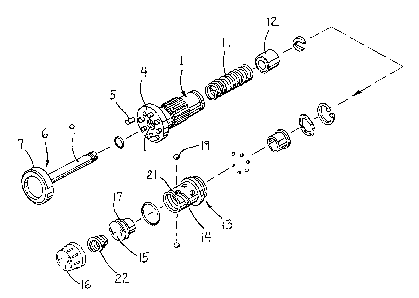
FI~. 1 is an exploded perspective view of the preferred
embodiment of the invention.
FIG. 2 is a plan view of a component part of the
preferred embodiment of the invention.
F~G. 3 is a side view of another component part of the
preferred embodiment of the invention.
FIG. 4 is a section view taken along line 4-4 of FIG. 6.
FIG. 5 is a section view of the assembled embodiment of
FIG. 1.
FIG. 6 is a section view similar to FIG. 4 but with the
invention in another position of its operation.
DETAILED DESCRIPTION OF THE INVENTION
Referring to the drawings, FIGS. 1-6 depict a preferred
embodiment of a collet for attaching a blade 3 to a surgical
saw. A blade shaft 1, or first member, is mounted in a
housing 2 in alignment with an axis. The blade shaft 1
transmits power from a source of power located in the saw to
the blade. The blade shaft includes a first clamping surface
4, perpendicular to the axis, which has upstanding drive pins
5 for engaging the blade. The blade is held against the first
clamping surface 4 and in engagement with the pins by a blade
clamp 6, or second member, which includes a second clamping
surface 7, perpendicular to the axis, with openings 8 in
alignment with the pins. The blade clamp 6 further includes
a blade clamp shaft 9 that is slidably mounted in a bore 10
through the blade shaft 1 so that the second clamping surface
can translate axially away from the first clamping surface
into an open, first, position in which the blade can be

--3--
inserted for engagement with the blade shaft as shown in FIG.
5. The second clamping surface can move axially toward the
first clamping surface into a closed, second, position in
which the blade is securely clamped as shown in FIG. 6. A
biasing means, such as a main spring 11, biases the blade
clamp toward the closed position. The main spring is disposed
around the blade clamp shaft and is constrained at one end by
the blade shaft and at another end by a spring retainer l~
connected to the blade clamp shaft.
The collet is opened via a mechanism that translates
rotational input into the translational movement of the second
clamping surface. This mechanism includes a hollow,
cylindrical, grooved retainer 13 fixed to the housing 2. The
grooved retainer has a helical groove 14 forming an opening
along its wall. Cooperating with the grooved retainer are a
plunger 15 and a knob 16. The plunger is disposed for axial
movement within the grooved retainer and contains an annular
groove 17 about its periphery. The plunger contacts the blade
clamp. The knob forms a hollow cylinder open on one end and
contains at least one verticai groove 18 formed in its inner
wall parallel to the axis as shown in FIG. 2. A ball ls is
disposed in the vertical groove such that, with the plunger
disposed in the grooved retainer and the knob rotatably
attached to the housing so that its inner wall surrounds the
grooved cylinder, the ball 19 protrudes from the vertical
groove through the helical groove and into the annular groove
as best shown in FIG. 5. Thus, rotational movement o~ the
knob propels the ball, which is confined to move within the
vertical groove, along the helical groo-ve. The ball is also
confined to move within the annular groove so that as the ball
progresses around the helical groove the plunger moves along
the axis. The blade clamp is pushed toward the open position
by the plunger when the knob is rotated in one direction and
the clamp is returned toward the closed position by the main
spring when the knob is rotated in the opposite direction.
The above described mechanism provides an operator with a
mechanical advantage in opening the collet so that relatively
high main spring forces may be employed for better blade
retention.

~iJ~'f~
--4--
The collet is further provided with a means for locking
the blade clamp in the open position for simplified operation
and cleaning and the plunger can be locked in the closed
position to reduce vibration. This locking action is provided
by detents 20 and 21 formed in the helical groove at each of
its ends. When the blade clamp is moved into the open
position (FIG. 5), the ball may be disposed in a first detent
20 shown in FIG. 3 where it is stably held due to force
exerted by the main spring 11. This first detent is such
that, when the ball is so disposed, the collet will remain
open without operator intervention. In order to return the
collet to the closed position the operator need only apply a
rotational force to the knob to move the ball from the first
detent. When the blade clamp is in the closed position, the
ball may be positioned in a second detent 20, shown in FIG.
1, where it is stably held due to force exerted by a conical
spring 22 located so as to bias the plunger toward the open
position. This reduces vibration in the plunger and knob.
The conical spring exerts substantially less force than the
main spring so as not to reduce the clamping load exerted on
the blade.
It will be understood by those skilled in the art that
variations in design and construction of the preferred
embodiment described above are possible without departing from
the spirit and scope of the invention defined by the appended
claims.

Representative Drawing
A single figure which represents the drawing illustrating the invention.
Administrative Status

2024-08-01:As part of the Next Generation Patents (NGP) transition, the Canadian Patents Database (CPD) now contains a more detailed Event History, which replicates the Event Log of our new back-office solution.

Please note that "Inactive:" events refers to events no longer in use in our new back-office solution.

For a clearer understanding of the status of the application/patent presented on this page, the site Disclaimer , as well as the definitions for Patent , Event History , Maintenance Fee  and Payment History  should be consulted.

Event History

Description Date
Inactive: IPC from MCD 2006-03-11
Application Not Reinstated by Deadline 2004-05-04
Inactive: Dead - No reply to s.30(2) Rules requisition 2004-05-04
Deemed Abandoned - Failure to Respond to Maintenance Fee Notice 2004-01-14
Inactive: Abandoned - No reply to s.30(2) Rules requisition 2003-05-05
Inactive: S.30(2) Rules - Examiner requisition 2002-11-04
Amendment Received - Voluntary Amendment 2000-02-16
Letter Sent 2000-01-20
Inactive: Status info is complete as of Log entry date 2000-01-20
Inactive: Application prosecuted on TS as of Log entry date 2000-01-20
Request for Examination Requirements Determined Compliant 2000-01-07
All Requirements for Examination Determined Compliant 2000-01-07
Application Published (Open to Public Inspection) 1993-07-28

Abandonment History

Abandonment Date Reason Reinstatement Date
2004-01-14

Maintenance Fee

The last payment was received on 2002-12-20

Note : If the full payment has not been received on or before the date indicated, a further fee may be required which may be one of the following

  • the reinstatement fee;
  • the late payment fee; or
  • additional fee to reverse deemed expiry.

Patent fees are adjusted on the 1st of January every year. The amounts above are the current amounts if received by December 31 of the current year.
Please refer to the CIPO Patent Fees web page to see all current fee amounts.

Fee History

Fee Type Anniversary Year Due Date Paid Date
MF (application, 5th anniv.) - standard 05 1998-01-20 1997-12-16
Registration of a document 1998-03-19
MF (application, 6th anniv.) - standard 06 1999-01-14 1998-12-22
MF (application, 7th anniv.) - standard 07 2000-01-14 1999-12-14
Request for examination - standard 2000-01-07
MF (application, 8th anniv.) - standard 08 2001-01-15 2001-01-03
MF (application, 9th anniv.) - standard 09 2002-01-14 2001-12-28
MF (application, 10th anniv.) - standard 10 2003-01-14 2002-12-20
Owners on Record

Note: Records showing the ownership history in alphabetical order.

Current Owners on Record
LINVATEC CORPORATION
Past Owners on Record
JOHN HENRY PASCALOFF
Past Owners that do not appear in the "Owners on Record" listing will appear in other documentation within the application.
Documents

To view selected files, please enter reCAPTCHA code :


To view images, click a link in the Document Description column. To download the documents, select one or more checkboxes in the first column and then click the "Download Selected in PDF format (Zip Archive)" or the "Download Selected as Single PDF" button.

List of published and non-published patent-specific documents on the CPD .

If you have any difficulty accessing content, you can call the Client Service Centre at 1-866-997-1936 or send them an e-mail at CIPO Client Service Centre.


Document
Description 
Date
(yyyy-mm-dd) 
Number of pages   Size of Image (KB) 
Representative drawing 1998-10-19 1 21
Representative drawing 2002-10-17 1 11
Abstract 1993-12-13 1 10
Drawings 1993-12-13 2 55
Claims 1993-12-13 4 117
Description 1993-12-13 4 157
Reminder - Request for Examination 1999-09-14 1 127
Acknowledgement of Request for Examination 2000-01-19 1 180
Courtesy - Abandonment Letter (R30(2)) 2003-07-13 1 165
Courtesy - Abandonment Letter (Maintenance Fee) 2004-03-09 1 175
Fees 1995-12-28 1 35
Fees 1996-12-19 1 94
Fees 1994-12-29 1 42