Language selection

Search

Patent 2087764 Summary

Third-party information liability

Some of the information on this Web page has been provided by external sources. The Government of Canada is not responsible for the accuracy, reliability or currency of the information supplied by external sources. Users wishing to rely upon this information should consult directly with the source of the information. Content provided by external sources is not subject to official languages, privacy and accessibility requirements.

Claims and Abstract availability

Any discrepancies in the text and image of the Claims and Abstract are due to differing posting times. Text of the Claims and Abstract are posted:

  • At the time the application is open to public inspection;
  • At the time of issue of the patent (grant).
(12) Patent Application: (11) CA 2087764
(54) English Title: ELECTRIC POWER BUSWAY ADJUSTABLE POWER TAKE-OFF-JOINT
(54) French Title: JOINT DE CONTACT REGLABLE POUR BARRE BLINDEE ELECTRIQUE
Status: Deemed Abandoned and Beyond the Period of Reinstatement - Pending Response to Notice of Disregarded Communication
Bibliographic Data
(51) International Patent Classification (IPC):
  • H02G 5/08 (2006.01)
  • H02G 5/00 (2006.01)
(72) Inventors :
  • HIBBERT, DAVID ALAN (United States of America)
  • WALKER, CLARENCE WILSON (United States of America)
  • HARTON, LYNN MACON (United States of America)
  • ANDERSON, JOHN DAVIS (United States of America)
(73) Owners :
  • GENERAL ELECTRIC COMPANY
(71) Applicants :
  • GENERAL ELECTRIC COMPANY (United States of America)
(74) Agent: CRAIG WILSON AND COMPANY
(74) Associate agent:
(45) Issued:
(22) Filed Date: 1993-01-21
(41) Open to Public Inspection: 1993-08-11
Availability of licence: N/A
Dedicated to the Public: N/A
(25) Language of filing: English

Patent Cooperation Treaty (PCT): No

(30) Application Priority Data:
Application No. Country/Territory Date
833,475 (United States of America) 1992-02-10

Abstracts

English Abstract


41PR-6822
ELECTRIC POWER BUSWAY ADJUSTABLE
POWER TAKE-OFF-JOINT
ABSTRACT OF THE DISCLOSURE
An electric power busway joint includes a plurality of metal
electrically conductive splice plates and electrically
insulative separator plates interleaved to receive the ends of
adjoining electrical busway power conductors. The busway joint
is defined by a pair of apertured side plates which receive an
elongated bolt electrically connecting the ends of the busway
conductors with the conductive splice plates by means of
spring-loaded Belville washers. A plurality of busway stabs
having elongated slots formed within one end are electrically
interconnected with the busway conductors by means of the
conductive splice plates and a separate elongated bolt. The
elongated slots allow the ends of the busway stabs to be ad-
justed accordingly while maintaining the integrity of the
electrical connection between the busbar connectors.


Claims

Note: Claims are shown in the official language in which they were submitted.

- 7 - 41PR-6822
CLAIMS
1. A busway power take-off joint comprising:
a pair of opposing metal side plates;
a plurality of interleaved electrically-conductive
splice plates and electrically insulative separator
plates arranged intermediate said side plates:
a first elongated bolt extending through said
splice plates, said separator plates and said side
plates;
a plurality of busbar stabs having first slotted
ends arranged within said side plates and second planar
ends extending a predetermined distance beyond said
side plates; and
a second elongated bolt extending within said first
slotted ends whereby positioning said first slotted
ends relative to said second bolt determines said
predetermined distance.
2. The busway joint of claim 1 wherein said first
elongated bolt is fastened to said side plates through
a first pair of Belville washers.
3. The busway joint of claim 2 wherein said second
elongated bolt is fastened to said side plates through
a second pair of Belville washers.

- 8 - 41PR-6822
4. A method of interconnecting a plurality of busbar
conductors together and to the power take-off plug
comprising the steps of:
providing a busway joint having a plurality of in-
terleaved electrically-conductive splice plates and
electrically-insulative separator plates arranged in-
termediate a pair of apertured metal end plates;
connecting a plurality of electrical power busbar
conductors to opposite sides of said splice plates by
means of a first elongated bolt traversing said splice
plates, said separator plates and said end plates;
inserting a plurality of busbar stabs terminating
in first slotted ends and second planar ends
intermediate said splice plates;
positioning said first slotted ends within a second
elongated bolt within said end plates; and
extending said second planar ends external to said
end plates.
5. The method of claim 4 including the steps of
translating said first slotted ends along said second
bolt to provide a first predetermined distance between
said planar ends and said end plates.
6. The method of claim 5 including the steps of
inserting said planar ends within a busway plug.

- 9 - 41PR-6822
7. The invention as defined in any of the preceding
claims including any further features of novelty
disclosed.

Description

Note: Descriptions are shown in the official language in which they were submitted.


~8776~
- 1 - 41PR-6822
ELECTRIC POWER 8USWAY ADJUSTABIE
POWER TAKE-O~FF-JO:lNT
BACXGROUND OF THE INVENTION
U.S. Patent 4,804,804 enti~led "Thermally Efficient
Power Busway Housing" describes a plurality of electric
power busbar conductors (hereaftar "busbars'l) that are
bolted together to provide excellent thermal transfer
away from the busbars and to hold the busbars ~gainst
strong electromagnetic repulsive forces. A thin layer
of epoxy resin deters the trans~er of cuxrent between
the busbars while, at the same time, promotes the
- 10 thermal transfer.
U.S. Patent 4,842,533 and 4,849,581 describe ad-
justable electrical joint connectors for connecting be-
tween corresponding pairs o~ electrical busbars.
: U.S. Patent 4,097,103 describes a busway plug as-
; 15 sembly wherein the busbars are electricall~ connected
to an electrical switch or circuit breaker to control
the trans~er of current through the busway systemO
To pr w ide external electrical connection with the
electrically connected busbars, the busway joint is
provided with a plurali~y of busbar stabs extending
from the busway housing as described in the

2~7~3i~
- 2 - 41PR-6822
aforementioned U.S. Patent 4,097,103. To prevent
inadvertent electrical circuit with the busbar stabs, the
busway plug assembly is mechanically joined to the busway
housing.
In prior art designs, th~ busway plug assembly is
custom-modified to fit the space requirements of the
busway system. It would be economically advantageous to
provide a busway system whereby a modular busway plug
assembly can be readily connected at the busway joint
without requiring custom modification of the busway plug
assembly or to the busway syste~ itself.
One purpose of the invention is to describe a busway
joint which connects two associated sections of electric
power busway and which also includes a plurality of ad-
justable busbar stabs.
SUMMARY OF THE INVENTION
A busway joint consisting o~ a plurality of inter-
leaved electrically-conductive splice plates and electri-
cally-insulative separator plates bolted together by
means of an elongated bolt and a pair o~ Belville washers
further includes a second elongated bolt and a plurality
of busbar stabs having elongated slots at one end. The
elongated slots allow the length o~ the busway stabs to
be adjusted without requiriny mechanical disconnection of
the busway joint.
,

2~77~
- 3 ~ 41PR-6822
BRIEF DESCRIPTION OF THE DRAWINGS
Figure l is a side perspective view of a busway
system and busway plug in accordance with the prior art:
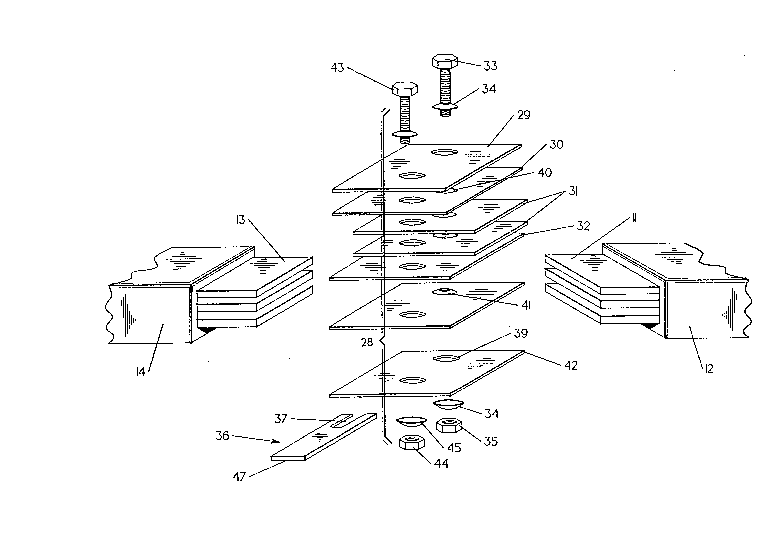
Figure 2 is a top perspective view in isometric pro-
jection of the busway joint prior to assembly accordiny
to the invention having adjustable busbar stabs;
Figure 3A is a top plan view of the busway joint of
Figure 2 assembled together according to the tsachings of
the invention with the adju table busbar stabs positioned
at a minimum distance from the busway joint; and
Figure 3B is a top plan view of the busway joint of
Figure 3A with the adjustable busbar stabs positioned at
a maximum distance from the busway joint.
DESCRIPTION OF THE PREFERRED EMBODIM~T
: lS Be~ore describing the adjustable power take-off joint
in accordance with the invention, it is helpful to review
th~ state of the art of electrical power systems and
busway power take-off plugs as describ~d within
aforementionad U.S. Patent 4,097,103. One such busway
system 10 is depicted in Figure 1 and consist~ of a first
busway section whic~ includes a plurality af busbars 11
supported within a first busbar housing 12 which are
joined to a second busway section which includ2s a plu-
rality of busbars 13 within a sacond busbar housing 14D
2S The first and second plurality of busbars are joined
together by means of a busway joint 15 which include top
and bottom side plates 16, 17 and which are joined
together by means of an elongated bolt 18 and Belville
'

2~77$l~
- 4 - 41PR-6822
washers 19. A plurality of electrically conductive
splice plates g electrically connect between the
adjoining busbars 11, 13. After positioning the busbar
stabs 20 extending from the busway joint 15 within the
busbar plug assembly 25 in the power take-o~f busway plug
22, the plate 21 attached to the busway plug is fastened
to the busway housings 12, 14 to prevent inadvertent
contact with the busbar stabs. The busbar plug assembly
25 includes spring-loade~ contact platas 26 and
corresponding angulated terminal stabs 27 that are
arranged for electrical connection with a circuit breaker
or electric switch (not shown). Electrical access to the
interior of the power take-o~f busway plug is made by
means of the side opening 24 in the housing 23.
The adjustable power take-o~f joint 28 in accordance
with the invention is depicted in Figure 2 between first
busbars 11 within first support housing 12 and second
busbars 13 within second support housing 14. The adjust-
able power take-off joint is similar to the splice joint
described in aforementioned U.S. Patent 4,842,533 and
contains similar apertured side plates 29, 42 within
which are arranged electrically conductive splice plates
31 and similar intervening insulative separation plates
30, 32 that are apertured to receive a ~irst elongated
bolt 33. With the busbars 11, 13 positioned within the
electrically conductive splice platss the elongated bolt
. 33 is inserted within a spring-loaded Belville washer 34,
~:: the aperture 38 in the side plate 29, the corresponding
`~ apertures within the separation plates and splice plates
..
`:`
.

--- 20~7~
- 5 - 41PR-6822
as indicated a~ 40, 41, the aperture 39 in the opposite
side plate 42, a s~cond Belville washer 34 all of which
are fastened together by means of the nut 35. The
slotted busway stabs 36, each consisting of an elongated
slot 37 formed within one end and an opposite planar end
as indicaked at 47 are then interleaved between the
corresponding splice plates and separator plates before
being attached to the ~djustable power take-off joint by
means of a separate elongated bolt 43, separake Belville
washers 45 and a separate nu~ 44.
The assembled adjustable power take-o~f joint 28 is
depicted in Figure 3A with first busbars 11 wi~hin ~ixst
housing 12 electrically connected with second busbars 13
within second housing 14 by means of first elongated bolt
33 and firs~ Belville washer 34. The top insulative
separation pla~e 30 electrically isolate~ the busbars
from the top apertured side plate 29. The slotted busbar
stabs 36 are depicted with second elongated bolt 43 and
~ second Bslville wa~her 45 arranged at the innermost part
; 20 of the elongated slot 37 to depict the shortest distance
Dl between the exposed planar end 47 of the slotted
busway stab and the edge 28A of the adjustable power
take-off busway joint. When a busway power take-off
plug, such as that depicted at 22 in Figure 1, is to be
connected with the adjustable power take-off joint 28,
: the elongated bolt 43 is loasened which allows the
slotted busway stabs 3~ to be slidably displaced relative
to the edge of the adj~s~able p~wer ~ake-of~ joint and
the power take-off plug by guiding the elon~ated slot 37

2~7r~$l~
- 6 - 41PR-6822
along second elongated bolt 43 to change the distance
that the planar end 47 of the slotted busway stab 36
extends from the edge of the ad~ustable power take-off
joint. This facilitates the inter-connection of the
aforementioned busway powex take-off plug with the
adjustable power taXe-off joint with fawer parts and
simpler operation than with the earlier-discussed prior
art design.
The adjustable power take-off joint 28 is depicted in
Figure 3B with the slotted busway ~tabs 36 moved to a
maximum distance D2 between the planar edge 47 of the
busway stabs and that the edge 28A of the adjustable
power take-off joint such that second elongated bolt 43
and second Belville washer 45 are close to the end of the
elongated slots 37.
It is noted that any intermediate distance between
the maximum and minimum extensions of the slo~ted busway
stabs 36 be realized by positioning the elongated slots
37 relative to the elongated bolts 43 without having to
re-adjust the first elongated bolt 33 and first Belville
washer 34 that electrically join the first and second
busbars 11, 13 within associated first and second ~upport
housings 12, 14.
Having thus described our invention, what we claim as
new and desire to sacure by LPtters Patent i~:

Representative Drawing
A single figure which represents the drawing illustrating the invention.
Administrative Status

2024-08-01:As part of the Next Generation Patents (NGP) transition, the Canadian Patents Database (CPD) now contains a more detailed Event History, which replicates the Event Log of our new back-office solution.

Please note that "Inactive:" events refers to events no longer in use in our new back-office solution.

For a clearer understanding of the status of the application/patent presented on this page, the site Disclaimer , as well as the definitions for Patent , Event History , Maintenance Fee  and Payment History  should be consulted.

Event History

Description Date
Inactive: IPC from MCD 2006-03-11
Time Limit for Reversal Expired 2001-01-22
Application Not Reinstated by Deadline 2001-01-22
Deemed Abandoned - Failure to Respond to Maintenance Fee Notice 2000-01-21
Inactive: Abandon-RFE+Late fee unpaid-Correspondence sent 2000-01-21
Application Published (Open to Public Inspection) 1993-08-11

Abandonment History

Abandonment Date Reason Reinstatement Date
2000-01-21

Maintenance Fee

The last payment was received on 1998-12-30

Note : If the full payment has not been received on or before the date indicated, a further fee may be required which may be one of the following

  • the reinstatement fee;
  • the late payment fee; or
  • additional fee to reverse deemed expiry.

Please refer to the CIPO Patent Fees web page to see all current fee amounts.

Fee History

Fee Type Anniversary Year Due Date Paid Date
MF (application, 5th anniv.) - standard 05 1998-01-21 1997-12-18
MF (application, 6th anniv.) - standard 06 1999-01-21 1998-12-30
Owners on Record

Note: Records showing the ownership history in alphabetical order.

Current Owners on Record
GENERAL ELECTRIC COMPANY
Past Owners on Record
CLARENCE WILSON WALKER
DAVID ALAN HIBBERT
JOHN DAVIS ANDERSON
LYNN MACON HARTON
Past Owners that do not appear in the "Owners on Record" listing will appear in other documentation within the application.
Documents

To view selected files, please enter reCAPTCHA code :


To view images, click a link in the Document Description column. To download the documents, select one or more checkboxes in the first column and then click the "Download Selected in PDF format (Zip Archive)" or the "Download Selected as Single PDF" button.

List of published and non-published patent-specific documents on the CPD .

If you have any difficulty accessing content, you can call the Client Service Centre at 1-866-997-1936 or send them an e-mail at CIPO Client Service Centre.


Document
Description 
Date
(yyyy-mm-dd) 
Number of pages   Size of Image (KB) 
Cover Page 1993-08-11 1 18
Abstract 1993-08-11 1 26
Drawings 1993-08-11 4 104
Claims 1993-08-11 3 63
Descriptions 1993-08-11 6 223
Representative drawing 1998-10-29 1 27
Reminder - Request for Examination 1999-09-22 1 127
Courtesy - Abandonment Letter (Maintenance Fee) 2000-02-22 1 185
Courtesy - Abandonment Letter (Request for Examination) 2000-03-06 1 172
Fees 1996-12-19 1 58
Fees 1994-12-15 1 62
Fees 1995-12-14 1 59