Note: Descriptions are shown in the official language in which they were submitted.
20~7~
Title of the $nvention
Ga~ifier Burner for Powdered 501id FuelB ~nd Method ~or Usi~g the
Same
B~clcq~ound .~f the Invention
~ield of the Invention
Thi~ invention r~late~ t~ a reduct~on smelter or ~melting
funl~ce for iron and non-ir~n metz~l~, and in more particula~ to a
gaslflcatlon burne~ for powdered solid fuel which ~er~es a~ the
source of reduc~ng gas and he~ for a ~inc r~duc:tion smelte~ or
~melting furnace.
D~scriPtion o~ th~ P~ior P.rt
In the most common Imperi~l ~meltln~ Proce~s (~SP) method
of pyrome'callurgic~l zinc ~melting, zinc sulf ide concentr~te i~
roa~;ted, and the lump sinter ob~ained through ro~ing 18 put
int~ the smelting furnace together wi~h ~he lump coke. The zinc
i5 evapora~ed ~ut, ~:o th~t a reduclng g~s containirlg the zinc
vapor is ~b~ained. ~he zinc vapor in this gas is absorbed by a
lead cpla~h c:ondenser, and reco~rere~ to o~ain crude zinc.
~ n comp~ri~on to oth~r pyromet~llurglcal ~melting meth-
od~, tht s ISP method ha~3 an advan~ag~ that lead anq zinc ~an be~
processed at the s~ne time, thu~ being very cos~ competiti~e.
However, r~cently due ~o ver~ lnten~ os~ co~pe~titlon,
the ~::ost competitivene~ OI this ISP m~3thod i8 very ineff lcien~ .
The rea~on is the hi~ah ~o~t of u~i~g l~mp coke.
On the other hand, in ~o~m~ri~s like Japan where ~h~ cost
of electrici'cy i~ high, hydrosn~all~lrgical smeltl~ al~3o un~a-
~ro~able .
2 0 8 7 8 7 8
`_
Therefore, in order to improve the cost competitiveness
of the ISP method and so on, many improvements to the
pyrometallurgical method of smelting have been proposed and
researched.
One of the most promising of these proposals has been
disclosed in Japanese Patent Publication No. Showa 61-28004,
"Injection Smelting of Zinc Calcine". In this method, slag
which has a Fe/SiO2 ratio close to that of the zinc
concentrate, and a crude lead metal, are contained
beforehand in the furnace, and the roasted powdered zinc
concentrate, a reducing agent, and highly oxygen-enriched
air is blown through a lance into the melt bath. Powdered
coke and/or fine carbon stuff is used as the reducing agent.
When compared to the ISP method, because powdered coke
and/or fine carbon stuff is used in the place of lump coke,
it is possible to greatly reduce the operating expenses.
However, in this method, because the retention time
that the powdered coke is in the furnace is very short, the
effective utilization of the powdered coke, or in other
words, gasification rate of how much of the carbon burns and
gasifys to gas, is much worse than the ISP method regardless
of how small the grain diameter of the powdered coke is
compared to lump coke. As a result, a large amount of the
2087878
-
unburned powdered coke is scattered on the post-process
condenser, hindering condensation of the zinc. Therefore
the rate of recovery for zinc is made lower.
Two inventions have been proposed to do away with this
problem. They are disclosed in Japanese Patent First
Publications No. Sho 62-80234 and No. Hei 1-129933. These
two inventions are both related to the blowing-in lance
method.
The invention described in Japanese Patent First
Publication No. Sho 62-80234 uses a double pipe construction
for the lance having outer and inner pipes. Fine coke is
supplied through the inner pipe, and oxygen-bearing gas such
as oxygen per se or oxygen-enriched air is supplied through
the outer pipe, and the fine coke and the oxygen-bearing gas
are mixed in the mixing section on the tip of the lance.
The invention described in Japanese Patent First
Publication No. Hei 1-129933 uses a zinc calcine supply
nozzle located in the center, and several supply nozzles for
mixing and discharging the fine coke and oxygen-bearing gas
located around the central zinc calcine supply nozzle.
Both of these inventions are characterized by the
mixing section located in the narrow portion of the nozzle
tip section where the fine coke and oxygen-bearing gas are
o87878
mixed, and then after mixing, the mixture is discharged into
the furnace from the nozzle outlet port at nearly the speed
of sound.
Use of the lance as described in both of the
aforementionod inventions improves the gasification rate of
the fine coke in a degree. However as time elapses, they
both experience a rapid decline in the gasification rate,
and also the zinc recovery rate declines very rapidly. The
reason being that the discharge velocity is so high, that
the tip of the burner is quickly worn away by the fine coke,
and thus the mixture condition of fine coke and oxygen-
bearing gas becomes poor causing a decrease in gasification
rate and combustibility.
Also, the fine coke which is blown using a lance as in
these two inventions, is gasified in an oxygen poor state
inside
- 3a -
~'
,
2~ ~ 878
the furnace, an~ bec:a~se the ~urn~ce tem~era~ure i~ kept below
15~, in orde~ to pro~ect the bri~3cs of the ~rn~e, th~re is a
limit to how ~ar the gasifi~ti~n rate of the fine ~oke can l:-e
impro~ed, ~gardle~ how well the f~ne coke and ~xygen-beaxi~g
ga~ are mixedl ~o~ the ~ollowin~ rea~on.
AQ is well known, in an oxy~en poor ~tat~, carbon, whiC~
i~ the maln compoI~ent of the $ine c:oke, i~ gasified according to
the fol lowing e~at ions .
C(OE) ~ 2(Çl) ~ C2 (~) Eq. 6
c(s) ~ ~2 (g3 - aco (~) Eq. 7
In oth~x word~;, oxygen first r~act~3 with carbon, ~ shown
in Equation 6, to forln CO~ depending on the amount oi- oxygen.
Ne~t, thls ~0;~ ~e~c:t~i with the remaining c:arbon, a~ shown ln th~
Equation 7, to fo~m CO. As i~ well know, the reaction t~f Equa-
tlon 6 i~ an exoth~rr~ic reaction ~hlch advanoe~ very ~uickly,
however the reaction of Equation 7 ls an endoth~rmic~ reactic~n,
an~ it~ rate of ~eaction ha~; a positive correla~i~n with tempera-
ture. At tempera~u~e~ ~round lSOO~, the ~ate of reaction o~
E~uation 7 i~ cc:mpar~tively ~low, ~nd in order to con~ert all of
the rerna~ni~g c:arbon into CO, ~he carbo~ m l~t r~main in th~
furnace for a lon~ time~ ~lowever, wh~n the two in~ention~ men-
tioned above are u~ed, the p~riod of ~ime that the carbon l~emain~
in the furnacs cannot be lengthened.
g~mnary c~f the Inv~ntion
The o~jective of th~ invention i~3 to pro~ ide a ~}asif~er
~urner for solid ~uel whic:h can maintain a high rate o~ gasifica-
tion for a long period of time.
In order to ~ol~re the aforemen~i~ned prohlem~, ~ ga~ifica-
20~78
tion bu~ne~ is provid~d t~ co~p~ifie a ~ombustlon chamber and a
p~e-mi~ing pipe in ~pecific dimen~ion~ ~o that ~ spaoe 1~
utilized fo~ rea~tion near the di~char~e port of the p~e-m~xing
pipe around the ~onical gas flow ~nto the combu~tion cha-b~r ~ro~
the prB-mixing pipe.
Brief ~e~ip~ion ~f the Drawlnq~
Fig. 1 ix a partial cro~s-s~ction~l view of the ga~ifica-
t~on burner of a fir~t e~bofliment of the invention:
~ ig. 2 is a dr~wing showing the relationship between the
oone ~haped ~as ~low, created by b~owin~ ga~ ~ro~ the blow pipe,
and the cylindric~l ~haped hood;
Fig. 3 is a p~tial cro~ ectional vie~ of one example
of the ga~ificat~on ~ur~er of a second embodim~nt of the inven-
tion
Fi~. 4 1~ a partial cro~s-~ection~l drawin~ of another
example of the gasific~tion burner o~ the ~econd embodi~ent of
t~e invention:
Fig. 5 i~ a gr~ph ~howing the relationship between the
mea~ured m ~alue and the ga~ification rate of the powdered coke
whsn the ga~ific~tion ~u~ner ~f the firxt embodiment of th~
invention ~s u~ed
Fig. 6 is a cro~s-~ectional drawing of the s~elting
furna~e having a gasification burner, u~ed for fi~din~ the rela-
tion~hlp sh~wn in Fig. S:
Fig. 7 i~ a graph ~ho~ing the conoentration dl~tr~bution
of CO~ and CO in ~he ~adial dlrection betw~en th~ cente~ and w~ll
of the reaction tower, o~atne~ in the examples of the fir~t em-
bodi~ent of this inventlon.
~Q87878
Descrip~ion of the Pref~rred ~ odiment~
In a fir~ diment oi ~ s inven~ion, a aa~ifier
~urner compri~e~ a comb~tion chambe~ having a ceil$ng w~th a
hole forme~l ln ~ t~ c:enter, and ~ pre-mixin~ pipe havin~ a no~zl~
lat~3rall~ located at the tc~p end ~ection o~ the pre-mixlng pipe
and ali~ned at lt~ low~r end ~ection with the hole in the ceillng
of the aforementfoned co~nbu~tion ch~mber. The p~e-mixing p~pe
and ~ombu~tit~n ch?mher are cor~c~entric, ~nd the horizont~l plane
formed by th~ ttom en~l ~ace o~ the pre-mix~ ng pip~ and the
lower ~urfac:e of the ch~mber ceillng ~ bstantially form~ rlght
angl~3s with the c~nte~ a,;t~i8 of the pre~mixing pipQ. The inxide
diameter of the pre-mixin~ pipe is a mm, the distanc~ from the
poin~ where the center axe~ o~ the noz~le and the prs-mixing pip~
c;ro~ e~ch othe~, to the bottom ~3nd of the pre mt xi~g pipe 1~
1 (el ~mm, and the inside d~ amet~r of ~he c:ombustion chamber i~ D
mm and the length i~ L nun, where 1 ( ~ d, and the an~le a
found by E~uation 8 be~ow i8 5 de~ree~ to 20 ~le~re~. It 1~
even m~re de~irable if A, foun~ by E~uation 9 b~low, is between 0
m~ to laO ~un. It i~ also desirable to in&tall a w~ter-cooled
~acket ~n at le~t one of the ~omb~stion rh~ r and the p~e-
mixing pipe.
tan a = ( D - ~ 3 / ~ ~ ~ Eq . 8
tan 12 degree~ = {(D - d~ / 2 - A~ / L Eq. 9
In a ~3eeond em~odim~nt of thi~ invention, ~1~b mixing
pipe~ are loca'ced on the cei l in~ of ~he combu~tian ~hAn~he~r of the
ga if lcation burner ~or powde~ed s~l~d fllel o~ the fir~t ~m~odi-
men~ of th~s in~entic:n. It i~ de~irahle that ~ev~ra~ ~b-mlxing
2~7878
pipes are equal~y ~pa~ed around th~ pre-mixing pipe, ~etween the
oute~ pe~iphery of ~he com~u~tion chamb~r and the pre-~ixing
pipe, 80 th~t they fo~m a concentric cir~le ~ith the pre-mixing
pip~ .
~ nother feature of thi~ inv~ntion relate~ to a method ~f
using the ga~lflcation bu~nQr for powdered ~olid $uel cf the
seco~d e~bodi~ent, and an oxygen-bearin~ ~as such as oxygen per
8e, air or oxygen-enrlched air and i8 characterized by making the
value of the ox~gen ratio m in the pre-mixing pipe obtained ~rom
Equa~ion 10, ~reater than th~ ax~gen ratio m in the ~ub-mixing
p~pes obtained from E~uation 10 . It 18 de~iirab~ e tha~ the oxy~en
ratio m ~n the p~e-mi~ln~ pipe i~ betwe~n 0.~ and 1~0. ~ls~, it
~æ deRir~ble to supply mOfi~ of the oxygen-bearing gas to the pre-
m~xing pipQ, and to Quppl~ powdered solid fuel to the pre-mlxin~
pipe ~o that the ox~gen ratio in the pre-mixing pipe is between
0.9 and 1.0 with the remain~ng oxygen-bearing ga~ and powdered
~olid fuel supplied to the ~ub-mixin~ pipes.
~ = (~mount of oxygen actually ~upplled) ~ ~Amount of
o~y~en required to oxidize all of the C and H in the fuel to
obtain C02 and H2~ Eq. 10
G~nerall~, when ~ blow pipe is u~ed to discharg~ gas into
the furnace, the blown gas forms a ~one-shaped gas flow~ The
space near the ~low pipe ~o~e the coni~al surface of the ga~
flow i8 not uEjed for re~tion and doe~ not help the reaction in
any way. Howe~er, by plac~ng a cylind~ic~l hood over thi~ ~one~
~haped flo~, it i~ po~si~le to cause the gas to ~e reciroulated
in the ~pace ~urrounded ~y ~he hood and the conical ~rface
formed by the ~ flow, The~fore, it is pox~i~le ~o extend thq
208787~
period of time that the ~as actu~lly remains in the furn~ce~ We,
the in~entor~, h~e utilized thi~ mechani~ in this invention.
The pre~e~red e~odiment~ of thls invention will be
~xplain~d below with reference ~o the d~awings.
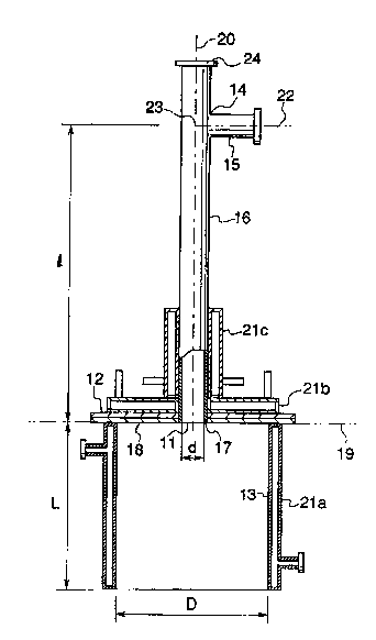
F~. 1 is o~ the ga~i$ication burner of a first emb~di-
me~t of thi~ ention. Thls ga~i~ic~tion bu~ne~ ~omprises a
~ombustion cham~er ~3 in whi~h a hole 11 i 8 formed i~ the ~enter
o~ the cbamber ceiling 12, and ~ pre-mixing pipe 16 which fi~
into the hole 11 in the ~h~mher ceiling 12 a~d ha~ a nozz~e 15
lo~ted ~t the top 8e~tion lg thereof. ~he p~e-mixing plpe 16
~nd ~he com~ustion cha~er 13 are arran~ed conoen~ric, ~nd th~
horizontal plane 19 including the bot~om end 17 of the pre-mi~ing
pipe 16 and th~ lower surfac~ 18 of the chamb~r ~eiling 12 forms
subGtantially right angle~ ~ith the center ~xi~ 20 o~ the p~e-
mixir~g pipe 16.
W~te~-~ooled ~acket~ 21a, 21~ and 21c are located in the
combu~tion ~.h~her 13, an~ ln the bot~om section of the ~h~hAr
ceiling 12 and ~he pre-mixlng pipe 16 re~pec~ively. The inte~n~l
diameter d of the pre ~ixing pipe 16 is 10~ mm, the di~tan~e
l(el) from the point where the c~nter axi~ ~ of the nozzle 15 at
the top sectlon ~4 of the pre-mixing pipe cros~e6 the cent~r axi~
Z0 of the pre-mixing plpe 16, to the bottom en~ 17 of the pre-
mlxing pipe 16 is 1000 mm, the internal ~iame~ex P o~ the combus-
tion chambe~ 13 ~ 50~ m~ and the ~ength L i~ 600 mm. ~18~, the
a~le a , found usin~ th~ afo~emen~loned equation 8, 18 18.4
de~reec, and ~he value of ~, found fro~ Equation 9, lx 70 ~m.
The value A of Egua~lon g i~ a parameter to indic~te the inte~val
between the conical ~urface of the ga~ flow and the ~ide wall of
2~87g78
the combu~ion chamber 13 at lts lower end.
Wh~n the a~o~ameIltioned ~ ication bu~ne~ i~ us~d,
cooling wa~er flows throu~h the water-co~ d iacket~ ~a, 21~ and
21c, and ai~ for car~i~r i. u~ed to blow the pow~r~ f~
into the p~e-mixiT~g pipe l~ from the top end ~4 of the pipe 16,
and indu~t~ial oxyg~n a~ ~n oxygen-bearing ga~ ia blown froln the
nozzle 15. As ~hown in ~ig. 2, reci~culation flo~ 35 o~ the
cc>~ v~tion ga~ are fornled ln~ide the com~ustion cl~hl3r 13.
In other wordfi, generally when a b~ow pipe is u~e~ to
di~char~e gas into the fu~na~e, the gag flow of the blown ~g
forms a conic~l shape a9 indicated b~ numeral 3~ ln Fig. 2. Tlle
~;pace near ~he blow pipe a~o~e the con~cal ~u~face 33 of the ga~
flow 32 is ~ ~Isad ~one and ln no way help~ the ~eaction a~ s~own
in Fig. 2. Howe~e~, by p~acing a cylindric:al hood 31 around thi~
conical gas flow 3~ i6 po~sible to cr~at~ recirculation flows
35 in the 2ip~ce 34 surrounded l~y the hood 31 a~d the conic~al
surface 33 of the ga~ f low 32, ~30 that it i~; posYible to exten~l
the residence ~ime c~ the ~a~ actually in the combustion ~
In ~he gasiflcation b~rne~ of thls f~rst embo~iment of
the in~rention, when the 8peed of th~ gas in~lde the pre-mixing
p~pe 1~ i9 S~OW, recirculat~on of the ~ombu~t$on ga~i a~ ~ho~n ~n
~ig. 2 cannot be formed insld~ th~ con~u~tion ch~ r 13. ~owev-
~r, thi s i ~ ~c~u~l ly not a Concern . U~cause, in order to main-
t~in ~n excellent n~ixture of powder~ed ~ol~d fuel suoh a~ powdored
c::oke or fine carbon stuf ~n~l oxygen-bearing gac, ~t i~ nec:e~ary
~hat the gas ~peed lnslde the pre-mlx~ng pipe ifi at least 5 n~/~ec
o~ Inore, and a~ long a~ thl~ condition i8 xatl~fied, ~he recir~u-
lation flow~ men~ioned ~ov~ will positi~rely oc:~cur.
~P~78~
When the powder~d solid fuel and oxygen-bearin~ ga~ a~
di~;~harged or ~pra~ed from ~he pr~e-mixing pipe 16, the ~pread
angle~ of the powdere4 fuel and oxygen-bearing ga8 are nearly the
~ame nea~ the end of th~ pre-mixing pipe 16, and th~t ~ngle
v~r~e~ normal ly be~ween 10 and 40 de~xees acco~ding to ~he diQ-
charge spe~ . When c;:o3ce i8 u;ed as the powdered -~ol id ~uel, ln
c~rder that abrasion of thc in~ide su~ace of the pre-mixing pipe
d~l~ to the coke doe~ not caus~3 a p~o~lem, the maximum ~IQ speed
~ust be kept to approximate~y ~p to 10 m~sec, and in this ca~e
the ~pread ~ngle 18 24 degree~3.
The s t ren~t h o f the af o rement i oned ~ec i rcu ~ ~t 1 on f 1 ow and
t~e life o~ the c~oml~u~;tion cham~er i~; dete~min~d by the relatlon-
ship between the s~r$ace of ~he cor~ica~ ~a~ flow, havin~ a ~pread
an~le 2 a , ~nd the po~;itlon of the 10~7er end of the comb~stion
chalnber. ~n ~ther ~ord~ he xec~rc~llatic~n flow ~e~omee 2;txon~er
the lower end of the co~nbustlon ~.h~lhh~r is sh~f~ed more into
the conical s~aped flow, and the life of ~he c:oml:~u~tio~ chamber
;hort~rled. Al~o, the recirc~latlon flow qui~::kly weakens as
the lower end of the cc)mbu~tlon chamber is ~ePa~a~ed f~m th~
conic~l gas flow, and ~he life of the combu~tic~n cha~};~er i8
1 engt hened .
hi~ f~r~t embodilnent of th~ invention, the in~ide
diameter of the pre-m~xin~ plpe ~ t~ken to be d nun, ~he ln~ern~l
diamet~r of the combu~tlon chamber i~ taken to be ~ mm anà the
length i~ L m~, and the spread an~e i~ tal~en to be ~,. The
value~ d, D, and L are $elected to sa~ y Equation 8 above wit~
the angle a between 5 ~nd 20 d~grees, bec:a~e the gasification
208?878
~llrner mE~de u~ing the~;e value~ ha~ good ga~ii lcation rAte of the
powdered ~olld ~uel ~nd good cc~m~us~ian cham}~e~ dura~llity.
Th~ max~ mum ga~ ~pe~d that can be u~e~ so that abr~L~3ion
in~ide the pre-mixing pipe does not become a problem depend8 on
th~ type o~ powder~d ~ol i~ fuel and the qual ity of the p~e-mixing
pipe. ~or example, lf powdered cok~ i8 u~ed a~; the powdered
solid fuel, the gas speed i~ ~pproximately 10 m/f~e~ ~nd in thifi
~a~e the ~pread angle i~ ~ de~rees~ In thi~i case, if d, ~, and
~ arQ selected u~ing Equation g above 80 that the value A i~ be~-
ween 0 an~ 100 nun, it is even m~e el'~ecti~e in in~;rea~ing the
life c~f the combu~tlon rh~ r.
The dimension~3 d, ~, and L are dete~lnined a~3 de~cribed
below.
F~rst, the total volum~ of th~ a~r for carrying powde~e~
~3olid fuel and the oxy~en-b~aring gas is taken to be W, the fl~w
speed V of the ga~ ;elect~3d ~o that there i8 no abrasion
call~ed inside the pre-mixing pipe, and d i~ ~Oun~ ~rom ~he E;qua-
tion W/V = dZ /4 7c 1 mm ) ~ Next, u~;in~ E~tion 6 and T~quation 7,
the aqlount of ox~ç~en-bear~ng ga8 W ' pro~uced ~nd the temperatu~e
T (ab~o~ute temperature) of the oxygen-bearing g~ ~rè e~timat~,
~nd uf~in~ t as the desired tim~ ~ha~ ~he ga~ ~emains ln the
combustion chatnbe~, the relationship given in ~quation 11 ls
o~tained .
D2 L/47t = W I ~t/273 Eq . 11
Then D and L are determlned ~ing Eq~lation~ 8 and 11 and
the v~lue ~, ~o th~ the ~gle a o~ 3~qua~ion 8 I s betwe~n S and
20 degree~.
N~xt, usirlg ~he obt~lned valu~s of P and I., u~ing E~ua-
2~87878
.
tion 9, D and L are selected so that the A value is between0 and 100 mm.
Normally the temperature T is between 2470 K and 2770
K. Therefore, it is necessary to install water-cooled
jackets in at least the combustion chamber and on the
chamber ceiling. Also, if highly oxygen-enriched air is
used as the oxygen-bearing gas, it is possible that the
combustion reaction may occur in the lower section of the
pre-mixing pipe. In this case, it is best if there is also
a water-cooled jacket in the lower section of the pre-mixing
pipe.
Mixing the powdered solid fuel and the oxygen-bearing
gas inside the pre-mixing pipe is a large factor for
increasing the gasification rate. There are two methods
which can be used to accomplish this objective. The first
method is to increase the gas speed. The other method is to
lengthen the residence time of the fuel and gas in the pre-
mixing pipe.
Since increasing the gas speed remarkably shortens the
life of the pre-mixing pipe, there are limits as to how far
this method can be used. Therefore, in this invention, a
good mixture of powdered solid fuel and oxygen-bearing gas
, . .
2087878
~ ,
is maintained inside the pre-mixing pipe by the following
process. Specifically, the time the oxygen-bearing gas and
the powdered solid fuel are in the pre-mixing pipe is
maintained sufficiently by keeping l(el)> Sd where the
distance l(el) mm from the point where the center axes of
the pre-mixing pipe and the nozzle cross each other, to the
bottom end of the pre-mixing pipe.
In this embodiment of the invention, as long as the
condition of l(el)> 5d is satisfied, in other words, 5d is
equal
- 12a -
20~7878
to or less than 1(~1 ), it i8 po~sible to have unifor~ gas ~peed,
ga~3 ~low den~it~r, and a uni~orm dl~tribution of powdered ~olid
fuel at every latera~ cro~3s-~ection in the pre-mixing pipe.
Tnerefore, the center o~ ~he ga~ flow blown in~o the com~uF~tion
~:hamber ooincides~ with the c~nter o~ the combu:3tion chamber and
~here i~ no sh~fting, and æo t~ere i~ no loc~lized wear to the
wall~.of the combu~sti~n chamber ~lue to the att~ck of the produced
reactlon ga~ l>eing o~f-c:ent~red or drifted,
~ ext a second em~odiment of t}lis lnvention will bq de-
~ribed .
E; i~. 3 and Fi~. 4 both ~how a ~ecor~d em~odim~nt of t~e
inventic~n. Both Flg. 3 and ~ig 4, are ~ros~-~ectional ~i~3ws of
~ afiification bu~ner that further compri~es two s~b-~ix~ ng pipe~
25a and 25b, located in the ceiling 12 of the combu~tion chambe~
of ths ga~i~icstion burner, and located aro~lnd the pre-mix~ng
pipe 1~ l'ormin~ a conc~3ntri~: circle with the pre-mixlng pipe 1~.
In ~. 3, the ~l~w di~ectio~ of the ~3ub~ ing pipex
~5a and 25b a~e faced sub~ta~ti~lly in ~he same di~ection a~, in
cther woI~d~ parallel ~o the blow direction of pre-mixin~ pipe }~.
In ~ig. 4, the 1:~70~4 direc~ion~ of the ~ub-ml~ing p$pe~; 25a and
~5b are faced in toward the center a~i~ 2a of th~ b~ow ~i rection
c)f the pre-~ixin~ pipe 16.
The provi~ion of the~3e ~;ub-mixing pipe~ in this ~econd
emboaimerlt of thl3 in~ention, 1~ to ~urthe~ improve utili~ation of
the unu~ed ~ipace or dead zone by the ~ecircul~tion flow whic:h has
occurred in the fir~t em~odim~rlt. In o~her word~, in the fir~t
embodi~ent of the in~ent,ion, the s~ren~th o~ the r~circulation
flow relies mainl~ on dimension~ of the pre-mixing pipe and th~3
2~87~7~
coml~u~tion ch~nber a~d on the ~1~3charge ~elocity fro~ the pre-
ml~ing pipe etc:., and so it 18 diffiC:ult to ~on~t~nt~ in~Ain
the optimum ~tate due to changes in operating c:c~ndit~on~3.
In thi~ sec~ond em~odiment of the lnvention, the purpo~e
o~ ~he ~ub-mixing pipe~ i~ to remo~e thls problem, and }~y blowln~
powdered solid fuel alone o~ powdered ~3olid ~uel ~2d oxyg~-
I:earlng Çla8 into the recirculation ~low, it ~g poRsible to mo~e
e~f~ciently u~ilize the u~u~ed ~3pace or dead zon~, toge~er with
the effectl3 o the ~e~irculation f}ow
The rea80n th~t the sub-mix~ ng pipes ~re locat~3d ~ n th~
com~ustlon ~hamber ceiling is ~hat lf they w~re located ~n a ~lde
wal~ of the combugtion chamber, tbe cone ~haped ga~ flow form~d
f rom the pre-mixing pipe would be greatly broken up, greatl~
reducing the strength of the rQcirculatlon flow.
l'h~ location and the number o~ ~ub-mixlng pipef~ lnstalled
in the cham~er ceiling i8 not e~p*clally flxed, howevel~, the~
should be u~ed to decrease as much ~Lg. possible the amount of
unu~ed spaoe or dead zone withc~ut ~au~in~ wear E~nd a~a~on to
the ~3ide wall of the c:ombustior~ cham~er, ~d the~ mu~t not break
up the conic:dl gas flow formed by the pre- mixing pipe, and there-
fore i~ ifi b~ if s~ver~l sub-mixln~ pipes ~re loc~ated at equal
inter~als around the p:re-mixing pipe forming a ooncent~ic cir~le
with ~le pI~e-mixiJlg pipe .
Next the method of~ using th~3 ~a~ifier burn~r of thi~
lnventlon w~ ll be expl~ined.
Fig. 5 i~ a graph ~howing the r~la~onshlp between ~he
~alue~ of nl measu~ed ~or the g~czifi~ation burner of the fir~t
embodiment and the ga~ification rate of pc)wdered coke, where the
14
~Q8787~
a~i~ of ~b~cissa repre~ents the m valu~, and the axis o~ ord$nate
doe~ the g~sificatlon ~ate of the powder~d coke~
This graph was obtained through the fol~owin~ ~teps;
mounting t~e ga~i~lcation bur~er, d~scrib~d ln the fir~t embodi-
ment of this inventi~n, at t~e top of th~ rea~tion ~h~ft ~1 of
the furnace, a~ ~hown in ~i~. S, fee~ing 120 k~/h of powder~d
coke (with a ~2~ C grade) to the pre-mixing pip~ 62 ~ the 4urner
thr~ugh th~ top end 63 u~ing air at 55 ~m3/h, ~upplying ~ pred~-
termined amount of ind~strial oxy~en (with a concentrat~on
90~) th~ough the end 6~ of the noz~le 64 locate~ ~t the ~pper
~lde portl~n of the pre~ ing pipe 6~, mea~uri~g the ~2~ CO,
and O~ conce~trations in the ex~us~ gas u~l~g the measure~ent
~ole~ (not ~hown in the figure) located in the upta~e ~ecti~n 66,
and then e~timatlng the gasif~catio~ rate of the powdered co~e
from the re~ult~ of the mea~urement.
~ : can be ~3een in ~ig~ ~, as ~he m value in~ease~ he
g~ificatlc~n rate alsa incxea~e~, and at an m value of 0.95, the
ga~iflcation rate i~ 1009~. The m ~alue required for makin~ the
gasifl~:ation rate 100% changes a little depeIIdiny c~n the ~mo~nt
of ~eeded coke and ~he rate of ox~g~n erlrichment air for combu~;-
tion in the oxygen-bearing gas, however fo~ all c:a~e~ it w~8
~ound to be le~is than l . 0 ~
Next, ~ g the d~vlce ~hown ln ~ig. 6, 2~0 kg/h ~f pow-
dered coke (with a 829~ C gr~de) wa; f~d in~ the pre-mixing p~pe
6~ throug~ the top end 63 usinS~ ai~ at 55 Nm3~h, and 280 Nm3/h of
$n~u~trlal oxygen (with ~ concen~ration of gO9~) wa~3 ~3upplied ~roln
the nozzle 64 located on the ~;ide of the upper pc~rtion of the
pre-mi~ing pi~e, and then ~he fuel and oxygen-bea~n~ ga~ were
~8787~
gasified. A water-~ooled ~ampler (no~ shown ln the flgure~ was
ln~r~ed through the mea~urement hole A located in ~he r~acti~n
shaft ~1 and t~e con~entratio~ of C02 and C0 were analyzed at a
p~e~cribed locatio~ in t~ rea~t~on sha~t ~1 and the a~ount of
unbu~ned powdere~ coke which a~¢umulate~ on the ~ampler w~ meag-
~red. ~he concentratlon di~trl~ution of CO2 an~ CO i~ the radiu~
direction from the center o~ the reac~ion shaft 61 to the ~lde
wall (furnace wall) of th.~ rea~tion ~h~ft 61 1~ ~hown in ~ig. 7.
Accord$ng to the di~tribution of unbu~ned powdered ~oke, the
amount of unburned powdered coke W~8 foun~ to be ~a~g~ in the
range fro~ the aenter of the reaction shaft to a point 360 m~
$rom th~ center in the dire~tion of ~he ~ide wall, ho~e~er, in
the ne~t 40 ~m are~, it suddenly decr~sed, and then from that
area to the ~ide wall it wa~ not de~ec~e~ at a~l.
~ he followin~ w~ found from the re~ults mentioned above.
~ig. 5 ~how~ th~t t~e ~arbon in th~ p~wd~rsd coke wa~ completely
gasified a~en when the m ~alue wa~ le~s than 1.0 through the
8tep~ a~ follo~; the carban i~ first o~idized to C02 ~hrou~h
Equation 6, and thcn acco~ding to Equat~on 7, it be~o~e~ CO, co~-
pleting gas1flc~tion. H~wever, the reacti~n rate ~f E~uation 7
is m~ch slowe~ than the reaction rate of E~uation 6, showing that
the rate d~termina~ ep is the re~tlon of Equa~ion 7, whlch ~&
backed ~y ~on~entional theory. Als~, ~g. 7 ~hows that the
concent~at$on o~ CO~ ~e~re~se~ ~hile ~he ~o~centration o~ ~O
increas~ along the dista~ce from the cen~er toward the side wall
of the reactlon ~ower. ~r~m th$~ result, and ~rom the re~ult
that there w~s no unburned powdered ~ke detected near the ~id~
w~ll of the reaction t~wer, it ~hows th~t all o~ the un~urn~d
16
2087~7~
powdere~ coke ~ti~r~d llp b~ the re~i~cu~ation ~lo~ r~ts as
s~ow~ in ~:quatic~n 7, and a~ll of the u~urned pc~wde~ed ~ol~e th~t
i~ not ~ti~red up move~ into th~ fur~Ac~ a~ ~, mo~t par'c of
wh~c~, although part o~ which }~ecome~ CO ac~or~ing t~ E~u~tiDn 7,
i8 exhaustod lnto the rc~A~ns2er.
Th~rafore, in or~er to ~urthe:~ ~ncr~as~3 the gasi~lcat~on
rate, ~t i8 neG~ ry tc> u~e th~ g~ ic~tion bu~n~r ~f the
~secon~ embo~iment o~ thi~ in~ention, an~l to ke~p the rela~ion~h~p
b~tween t~ powderQ~I 80~ id ~uel an~l the oxygen-bearing ga~ ~up-
p~ied to the pre~mixing pip~ to inc~rease ~he m val~ as hi~h a~
possible, and to re~ulate ~he entire ~alance ~l~ing the ~u~-mixing
pip~, Alsc~, a~ can b~ seen in Fig. 5, lt i~3 daslr~bl~ th~t the
I~ela~ionship ~setween th~ powdered 2;olld fuel ~nd the oxyge~-
3~arin~ ga~ fiupplie~ to the p~e-mi~cin~ pipe ~hou~d 1~3 k~pt ~o a~
to provlae the m ~alue between 0.9 and 1.
A specliied exa~pl~ ~f t~i~3 metho~ i8 explalne~ in d~tail
below, by feeding ~2% C powdered coke into th~ pre-mi~ing pipe
u~l~g air, ~d llsing 90% purit~ industri~l ox~gen t~ form ~n
~x~gen~ ring 5~d~ ~avlng a~} oxy~en <~once~atton of 7~9~ to
~btai~ a gas o~ C02:~0 ra~io of 0.5 (C02/C0 - O.S~.
In or~er to obtsln wlth ~ }00% ga~1fication ra~s ~ gas of
C02:C0 ratio of 0,5 ~COz/CO ~ 0~5), ~0~ ~m~ of o~y~en
is ne~3e~ fo~ 100 kg o~ p~w~lered coke. A~so, in ord~r to have
complete c;omb~st~on and have the ent~re an~oun~ of ea~bon $orm
C02, 153 Nm3 o oxy~e~ ~ required. ~refore, ln this~
case the m ~alue become~ 10~ I~m3/1~3 Nm3= O. 67.
The o~y~e~ ~alance i8 given by Eq~ on la below.
0.21 Vair + 0.9 VO~ - 10~ E:q~ 12
~ ~ ~ 7 8 7 a
~ ere, Vair is the volu~e of air ~or ~:arrier, and ~02 i~;;
~he volume of industrial ~xygen for enrich~ent.
Also the oxygen concentration i~3 given by Equation 13
bel ow .
1~2/ ('irair + V02 ) = O . 75 Eq. 13
By ~olving Equation~ and 13, the value~ Vair = 30
~m3, and V02 = 106 Nm3 are obtained. S~nce the amount
of pc~wder carried by the air i~ limited to at most abou~ 10 kg
p~r kg of ga;, there i~ no problem in this example with u~n~ 2 . 6
kg of powder pe~ kg of g~; ( 100 ks~ /30 Nm3 x 22 . 4 Nm3 per
mole/28.8 kg per mole = 2.~k~ powdsr/kg ~aE;).
An e~ample of distribution amon~ t~e pre~mixing pipe and
E~ub-mixing pipe~ using the abo~e re~ults ~ ~hown below.
Ta}~le 1.
Pre-mixingSub-mixing Total
PiPe Pipes
~ine coke 80 kg/h ~0 k~/h 100 kg/h
Ai r 2~ Nm3 6 Nm3 30 Nm3
Indu~trlal Oxygen 95 N~3 11 Nm~ 106 Nm3
m Value O . 74 0, 37 0 . 67
In table 1, a diQtributor i~ used to di~;tribute ~he air
flow including the powdered c~ e, at a ratio o~ 8: 2, to the pre-
mixing pipe and ~ub~mixing pipe~3, while g~% of the indu~3trial
oxygen is blown into the pre-mixing pipe and the rem~inder of th~
~nduxtrial oxygen i~3 blown into the sub-mixing pipes.
18
8 7 ~
Tabl e 2
Pre mixin~ Sub-mixln~ Tot~l
Pipe . PiP~
Fine coke 67 ky/h 33 kg/h 100 kg/l
Ai ~ 20 .1 Nm3 9 . 9 Nm330 Nm3
~ndu~trlal Oxygen106 Nm3 o Nm3 106 Nm3
m Value 0.97 0.04 0.67
In table 2, a distributor i8 used to di~3trlbute an air
flow lnc~udln~ the ~ine coke, ;~t a ~tio e~ua~ to the m value, to
the pre-mi~ing pipe, while all of the industrial oxygen i~; ~lown
into the pre-mi~ing pipe. Although a sllbEitantlal amount ~f
oxygen-enrichetl ~ir muqt be used, because the m tralue in the pre-
~ixlng pipe 1~ greate~ ~han 0 . ~5, it i8 expected that a ~igh
~a~ificatlon ra~e ca~ be obtained
~ lso, the ~upply to the ~ub-mlxing p~pes, doe~ not depend
on the alr $10w with fine coke, and c~n be performed b~ ~ropp$ng
the fine co~e using a rot~ry v~l~e, and :0 in thls ~:a~3e, lt i~
po~ ble to 8upply the entlre amc~unt of alr fo~ carrler to the
p~e-mixing p$pe.
ample ~
82g~ car~on grade f irle coke i:3 u~ed, and in order ~o
obt~in a reductlon ga~ ha~ing a C~02:CO ratlo of 0.5 (C0;~/C0 =
~.5), the ~a~ificatlon burner of ~h~s inventlon i~; for7aed based
on the conditlon~ shown in Table 3.
20~7~78
Table 3
~ine Coke 200 k~h
O~ b~aring g~ Oxygen rlch ai~ 270 Nm3/h
(ozygen concentrat~n 16%)
~reakdown Feed air S5 Nm3/h
gO% pure indu~trial ox~gcn ~15Nm3/h
Ga~ velocl~y ln the 10 m/~ec
pre-mi~ng pipe
Estlmated temperature 2~73 K
~n combu~tion chamber
Residence time in 150
c~mbustion chamber
A 70 mm
~ cc~dlng t~ the a~o~e condi~i~ns, d i8 100 mm. U~in~
thi~ valu~ and with A = 70 ~m, from Equati~n 9 ~nd Equat~on 11, D
be~ 00 ~m and L be~omes ~00 mm. U~in~ these val~e for d,
P, and L, an~le a beco~e~ 18.4 dcgrees, uslng ~ua~ion 8. Next,
u~ing these value~ ~nd with 1 e 100 mm, the ga~ifica~ion ~u~ner
iY made as shown in Fig. 3, an~ a~xanged on t~p o$ the urnace
reaction ~haft a~ ~hown ln ~ig. ~, and operatlon wag te~ed for 3
da~s using the de~isn conditions mentioned above. ~ux~ng t~at
time, exhau~t gas i~ sampled thxough the measur~me~t hol0
(not ~hown in ~hs figure) of th~ uptake~6, and the C02, ~O a~
2 concentratlon~ were analy~e~ using the Or~at metho~. A~t~r
e~amining th~ o~t~ined values, it was found that there wa~ very
little change ove~ the three ~ay period, ~d the ave~a~e value~
were CO2 - 39.5%, CO = 4~.S%, and O~ = O~. Al~ the re~ult~ of a
ma~s balance te~t ~howed that 90% ~arbon o~ the fin~ coke wa~
~08787~
gasified. ~owever, the CO2:CO ra~lo did not become ~.5.
When the in~ide ~rf~ee o~ the ~ombu~tion chamber wa~
exa~ined after the tes~ wa~ f~ni~hed, the ashe ~nStituents of
the fine coke ~e~e ~elted and had uniformly covered the entire
inner s~rface ~ith a ~ layer havlng a thi~kn~ of approx-
imately 20 mm, however there wafi no vl3ible wear or abr~ion
cau~ed by the impact of th~ ~lne cok~.
E~CaUnP1e 2
In ~h~ 8 example, the amount o~ indus~rial oxygen ~ed wa~
192 Nm3/h, ~nd the same ga~ificati~n burner ~8 Example 1 wa~
u6ed. ~peration wa~ te~ed for 3 day~. The ~ver~e c~ncehtr~-
tion val~es ~ve~ th~ three day~ of C0~, ~0, and 0~ in the exhau~t
gas were ~ound to be, C02 - 27.5~, C0 ~ 54.0 %, 2 = ~- Al80,
the ~a8~ ~a1an¢e re ult~ gave a ga~i~icatlon rate o~ gO~. There-
fore, ~n thi~ example, it w~s po~s~ble to achieve a C02 :CO ratio
~f 0.5 wlth a ~asificat~on rate of 90%.
Example 3
In thls example, two ~ub-mixing plpe~ with internal
dia~eters of 25 mm were located on the cc)mbu~tion chamb~r ce~ ling
of the gasific~tion burner of Example 1, ~o that they were pa~al-
lel with th~ pre-mlxing pipe ~s can be seen i~ Fig. 3. T~e
~7perat1 on wa~; te~ted ~or 3 days ~lsln~ the Eiame c~onditioxls a~
Example l. X~ ~hl~ example, :~3 of the total amount of mixt~r~
of fine coke and fee~l air w~s supplied to the pre-mix~ng pip~,
and the remaining 1/3 wag e~ual ly divided and ~3upplied to ~oth of
the ~ub-mixing p~ pes. Al~:c;, the m valu~ o~ ~he pre-mixing pipe
and both of the ~ob-mixlng p~pes wa~ made to ~e O . ~7 . 'rhe ~ve~-
a~e concentra~ion values ove~ the three d;~y!3 ~f C02, CO, and 2
~087~78
in the exhau~t gas ~ere found to be, C02 - 3S.0%, CO = 47. ~ 2
- 0%, and the ~asifl~ation rate found ~rom t~e ~a~ balan~e was
g4%.
Ex~mple 4
In thi~ ex~mple, ex~ep~ that the ~low d~rection of the
~ub-mixing pipes was pointed toward tho center axi~ of the pre-
mi~lng pipe a~ shown ln Fi~. 4, the opera~ion was te~ted f~r 3
day~ in the ~ame manner a~ for example 3. The averag~ c~nc~ntra-
tion va~e~ ov~r ~he three days of C02, CO, and 2 in the exhau~t
ga~ were ~ound to ~e, C02 - 37.0~, CO = 44.0 ~, 2 = %, and the
gasification r~te ~ound fro~n the mas~ b~lance was 9~%.
ExamPl~ 5
In thi~ example, excep~ that the entire amount of indu~-
trial oxygen was supplied to the pre-mixing plpe, operatio~ was
te~ted for 3 days in the same manner as in Example 3~ ~he m
~alue of the pre-mixin~ pipe was made ~o be ~.g9 and the m value8
of ~oth ~he sub-mixing pipes were m~de to be 0.03. The average
~o~c~n~t$on valu~s o~e~ the three ~ays o~ C02, CO, and 2 in
the ex~aust ga~ were found to ~, C02 ~ 32.5~, CO - 49.5 %, 0
0~, and the ~as~fic~tion rate ~o~n~ f~om the mas~ balance w~g
96%.
comP~rison Ex~ple
Except t~at }00 Nm3/h o~ the 1ndustr~al o~ygen was 8Up-
plied ~o the pre-mix$ng p~pe and th~ remalning of the ~ndu~trial
oxygen wa~ 8upplied to the sub m~ing pip~s, the opera~on wa~
te~ted for 3 days ~n the same manner a~ Example 3. The m value
for the pre-mixing pipe wa~ 7~ a~d the m value~ for th~ sub-
~ixing plpes were 1.05. The average concentration values over
~OS~878
the ~hr~e d~ys ~f ~0z, C0, a~d 0~ in ~he exha~st ga~ were found
to be, C02 - 46.~, C0 = 34.0 ~, 2 ~ 0~, ~nd the g~siflcation
rate f~und f~om the m~88 balance was 85%.
By u~ing the ga~lfication ~u~ne~ of this invention, lt i~
po8~ible to a~oid con~a~t between the powde~ed ~olid fuel ~nd the
~lfle wal 18 of the ~ombu~tion chamber, and it 1~ po~ible to
lengthen the retentlon time the powdere~ solid ~el in the com-
bu~tion chamber b~ creating a recir~latlon flow in the combu~-
tion chamber an~ efflciently utilizlng this recirculatlon flow~
Al~ it i~ p~lble to obt~in a ~table high gasifica~ion rhtq for
a long period of time. ~y ~sing th~ method featured b~ thi~
in~entlon, it 1~ po~ible to even further ta~e advantage of ~he
g~lficatio~ burner of thi~ i~vention.
~ lthough the pre-mixlng pipe ha~ its lowe~ end aligned
wi~h the lower ~urf~ce o~ the cellin~ in th~ embodiment men~ioned
a~ove, the pre-mix~n~ pipe ma~ project f~om ~he ~ower surface of
the ceiling 50 long a~ ~he recir~ulation flow~ are p~oduced about
the ~onl~al lnJection ~low.