Language selection

Search

Patent 2088112 Summary

Third-party information liability

Some of the information on this Web page has been provided by external sources. The Government of Canada is not responsible for the accuracy, reliability or currency of the information supplied by external sources. Users wishing to rely upon this information should consult directly with the source of the information. Content provided by external sources is not subject to official languages, privacy and accessibility requirements.

Claims and Abstract availability

Any discrepancies in the text and image of the Claims and Abstract are due to differing posting times. Text of the Claims and Abstract are posted:

  • At the time the application is open to public inspection;
  • At the time of issue of the patent (grant).
(12) Patent Application: (11) CA 2088112
(54) English Title: STOPPER DEVICE FOR AN AUXILIARY HANDLEBAR
(54) French Title: ARRET POUR GUIDON AUXILIAIRE
Status: Deemed Abandoned and Beyond the Period of Reinstatement - Pending Response to Notice of Disregarded Communication
Bibliographic Data
(51) International Patent Classification (IPC):
  • B62K 21/14 (2006.01)
  • B62K 21/12 (2006.01)
  • F16B 7/02 (2006.01)
(72) Inventors :
  • LIAO, JIM (Taiwan, Province of China)
(73) Owners :
  • HSIN LUNG ACCESSORIES CO., LTD.
(71) Applicants :
  • HSIN LUNG ACCESSORIES CO., LTD. (Taiwan, Province of China)
(74) Agent: BLAKE, CASSELS & GRAYDON LLP
(74) Associate agent:
(45) Issued:
(22) Filed Date: 1993-01-26
(41) Open to Public Inspection: 1994-07-27
Examination requested: 1993-01-26
Availability of licence: N/A
Dedicated to the Public: N/A
(25) Language of filing: English

Patent Cooperation Treaty (PCT): No

(30) Application Priority Data: None

Abstracts

English Abstract


Abstract
A stopper device comprises a rod member having a diameter
which is the same as the outer diameter of the free end of the
auxiliary handlebar. The rod member further includes a fastening
shaft attached to the lower end portion of the rod member. The
fastening shaft can be inserted into the free end of the auxiliary
handlebar securing the rod member thereof. A supporting rod member
is angularly formed on the upper end of the rod member and provides
a solid support to the thumb of the rider.


Claims

Note: Claims are shown in the official language in which they were submitted.

THE EMBODIMENTS OF THE INVENTION IN WHICH AN EXCLUSIVE PROPERTY
OR PRIVILEGE IS CLAIMED ARE DEFINED AS FOLLOWS:
1. A stopper device for an auxiliary handlebar comprising:
a rod member having a diameter which being the same as
the outer diameter of the free end of the auxiliary handlebar, said
rod member including a fastening shaft attached to the lower end
portion of said rod member, a circular recess having a hole in
connecting with the middle portion of said fastening shaft being
provided in said rod member, and a supporting rod member being
angularly formed on said upper end of said rod member providing a
solid support to the thumb of the rider;
a locking block having a threaded recess in its middle
portion, said locking block being suitably attached to said lower
end of said fastening shaft; and
a bolt member being inserted into said hole of said
circular recess and extending through said middle portion of said
fastening shaft and screwed into said threaded recess of said
locking block.
2. A stopper device as recited in claim 1, wherein said
fastening shaft includes an inclined portion in its lower end
portion.
3. A stopper device as recited in claim 1, wherein said
locking block includes an inclined portion in its upper end portion
which is in contact with said inclined portion.

Description

Note: Descriptions are shown in the official language in which they were submitted.


2 ~ 8 ~
This invention relates to a stopper device, and more
particularly, to a stopper device for an auxiliary handlebar of a
bicycle.
The handlebar of a bicycle, especially those of racing
bicycles, is provided with an auxiliary handlebar in the end
portion of the handlebar. Most auxiliary handlebars are formed
directly at the end portion of the handlebar. Another type of the
auxiliary handlebar i8 one which is an individual device and
attached to the free end of the handlebar.
The function of the auxiliary handlebar 40 is to provide
a strong support of the rider, especially in racing. As shown in
Figure 1, the auxiliary handlebar 40 is a simple tubular rod
member, straight and without any stopper. When the rider grasps on
the auxiliary handlebar 40, the friction between the auxiliary
handlebar 40 and the palms becomes relatively low as the rider
increases the speed of the bicycle, since in this case, the weight
of the upper body concentrates largely on the hand. This will
bring a negative effect on the rider since his palms will slide
over the auxiliary handlebar 40. Should the bicycle become
unstable due to the rider's palm ~liding over the auxiliary
handlebar 40, the rider might be injured by an accident.
.' ~, !, ., , , . , ' , ,
~ . . .. ' . ' ~ '~, ' ' ' . , ',

- ?
20~ 2
It is the primary object of the instant invention to
provide a stopper device to the auxiliary handlebar of a bicycle
which device is attached to the free end of the auxiliary
handlebar, allowing the auxiiiary handlebar to furnish a strong
support to the palms to avoid any sliding motion thereof.
The stopper device accordin~ to th~ p~ ent invention
comprises a rod member having a diameter which is the same as the
outer diameter of the free end of the auxiliary handlebar. Said
rod member further includes a fastening shaft attached to the lower
end portion of said rod member, said fastening shaft capable of
being inserted into said free end of said auxiliary handlebar
securing said rod member thereof. A support1ng rod member which is
angularly mounted on ~aid upper end of said rod member provides a
solid support to the thumb of the rider.
Other features and advantages of the present invention
will become apparent when the following description is read in
conjunction with the accompanying drawings, in which:
Figure l is a typical auxiliary handlebar of the prior
art;
Figure 2 is an exploded perspective view of the stopper
device according to the instant invention;
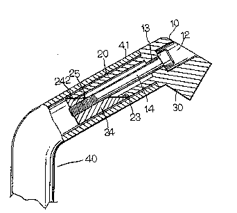
Figure 3 is a cross-sectional view of the stopper device
according to the instant invention as secured to the free end of
the auxiliary handlebar; and
, ~,;
. "
. . .
.

2~$~ 2
Figure 4 is a perspective view of an auxiliary handlebar
having a stopper device secured in the free end thereof.
Referring to Figures 2 and 3, the stopper device 1
according to the present invention comprises a rod member 10 having
a diameter which is the same as the outer dia~eter of the free end
41 of the auxiliary handlebar 40. Said rod mem~er 10 further
includes a fastening shaft 20 attached to the lower end portion 11
of said rod member 10. Said fastening shaft 20 can be inserted
into said free end 41 of said auxiliary handlebar 40 securing said
rod member 10 thereof. Said rod member 10 further includes a
circular recess 12 and a hole 13 is provided in said circular
recess 12, which hole 13 extends into the middle portion 21 of said
fastening shaft 20. A bolt member 14 can be inserted into the
middle portion 21 of said fastening shaft 20. Said fastening shaft
20 further includes a inclined portion 23 on the lower end portion
22 thereof. Said fastening shaft 20 further includes a locking
block 24 having an inclined portion 242 which is attached to the
inclined portion 23 of said fastening shaft 20. Said locking
block 24 further includes a threaded recess 25 in the middle
portion in which said bolt member 14 can be secured. A supporting
rod member 30 which is angularly formed on the upper end of said
rod member 10 provides a solid support to the thumb of the rider.
In assembling the stopper device 1 according to the
instant invention, said bolt member 1~ is first in~erted into said
hole 13 of said circular recess 12 and extended into the lower
portion of said fastening shaft 20. Said locking block 24 is then
~ '
, .
~ , ' '' ' ~. '
:

attached to said bolt member 13 with its threaded recess 25. The
assembled stopper device 1 is then inserted into the free end 41 of
said auxiliary handlebar 40. By rotating said bolt member 13, said
locking block 24 will move closer to said fastening shaft 20
splitting each other along their inclined portion 23, 242 toward
the inner wall of said auxiliary handlebar 40, consequently
securing said rod member 10 thereof.
Referring to Figure 4, said supporting member 30 provides
a solid support to the thumb of the rider. Hence, the rider can
grasp on said auxiliary handlebar firmly without any possibility of
his palm slipping out thereof.
Although the present invention has been described in
connection with the preferred embodiment thereof, many other
variations and modifications will now become apparent to those
skilled in the art without departing from the scope of the
invention. It is preferred, therefore, that the present invention
not be limited by the specific disclosure herein, but only by the
appended claims.
: . . . , ':, . ' ,, , '

Representative Drawing
A single figure which represents the drawing illustrating the invention.
Administrative Status

2024-08-01:As part of the Next Generation Patents (NGP) transition, the Canadian Patents Database (CPD) now contains a more detailed Event History, which replicates the Event Log of our new back-office solution.

Please note that "Inactive:" events refers to events no longer in use in our new back-office solution.

For a clearer understanding of the status of the application/patent presented on this page, the site Disclaimer , as well as the definitions for Patent , Event History , Maintenance Fee  and Payment History  should be consulted.

Event History

Description Date
Inactive: IPC from MCD 2006-03-11
Time Limit for Reversal Expired 1998-01-26
Application Not Reinstated by Deadline 1998-01-26
Deemed Abandoned - Failure to Respond to Maintenance Fee Notice 1997-01-27
Application Published (Open to Public Inspection) 1994-07-27
All Requirements for Examination Determined Compliant 1993-01-26
Request for Examination Requirements Determined Compliant 1993-01-26

Abandonment History

Abandonment Date Reason Reinstatement Date
1997-01-27
Owners on Record

Note: Records showing the ownership history in alphabetical order.

Current Owners on Record
HSIN LUNG ACCESSORIES CO., LTD.
Past Owners on Record
JIM LIAO
Past Owners that do not appear in the "Owners on Record" listing will appear in other documentation within the application.
Documents

To view selected files, please enter reCAPTCHA code :


To view images, click a link in the Document Description column (Temporarily unavailable). To download the documents, select one or more checkboxes in the first column and then click the "Download Selected in PDF format (Zip Archive)" or the "Download Selected as Single PDF" button.

List of published and non-published patent-specific documents on the CPD .

If you have any difficulty accessing content, you can call the Client Service Centre at 1-866-997-1936 or send them an e-mail at CIPO Client Service Centre.

({010=All Documents, 020=As Filed, 030=As Open to Public Inspection, 040=At Issuance, 050=Examination, 060=Incoming Correspondence, 070=Miscellaneous, 080=Outgoing Correspondence, 090=Payment})


Document
Description 
Date
(yyyy-mm-dd) 
Number of pages   Size of Image (KB) 
Abstract 1994-07-26 1 14
Claims 1994-07-26 1 30
Drawings 1994-07-26 3 36
Descriptions 1994-07-26 4 127
Representative drawing 1998-08-19 1 12
Fees 1996-01-24 1 31
Fees 1995-01-30 1 27
Fees 1994-12-19 1 35
Prosecution correspondence 1996-02-19 2 35
Examiner Requisition 1995-08-21 1 57