Note: Descriptions are shown in the official language in which they were submitted.
2088~7
FIELD OF THE INVENTION
The present invention relates to a clamping assembly for an
injection moulding apparatus.
5 BACKGROUND OF THE INVENTION
Injection moulding apparatus typically comprises fixed and
movable load-bearing platens which are adapted to clamp between them
respective halves of a two-part mould. By means of an hydraulically or
mechanically operated ram, pressure is applied to the movable platen so
10 as to clamp together the two halves of the mould into which molten
plastics material is then injected at pressure which can often be very high.
In order to ensure that the two sections of the mould are not displaced
with respect to each other as a result of the high pressure injection of the
plastics material, a high clamping force has to be applied so as to hold
15 together the two sections of the mould.
Hitherto proposed apparatus for achieving these objectives
are well known in the art and have been available for many years. Thus,
for example, U.S. Patent No. 3,128,501 (J.E. Borah) describes a power
operated multiple press,~the principles of which have changed little since
20 the publication of this patent. Borah describes an apparatus which
includes fixed and movable platens which are slidably supported with
- 2 - 2088447
respect to each other by means of four corner posts or tle
bars located respectively at the four corners of the two
platens, such that the movable platen may slide along these
posts towards and away from the fixed platen. The two halves
of a mould are substantially symmetrlcally supported by facing
surfaces of the two platens, the clamping force being directed
along an axls whlch is substantlally colllnear wlth the axls
of symmetry of the mould.
With such known structures, the presence of the four
tie bars seriously limits the accessibillty of the region
between the platens insofar as the introduction and removal of
the mould sections are concerned. This limitation is
particularly troublesome when one bears in mind that the mould
sectlons can be of significant size, complex shape and
significant weight and require to be manoeuvred into position
and removed therefrom using mechanical handling equipment.
Furthermore, this relative inaccessibility of the clamping
space seriously limits the degree of automation which could
otherwise be employed in connection wlth the introduction and
removal of the mould sections.
It is an ob~ect of the present invention to provide
a new and improved clamping assembly for an in~ectlon mouldlng
apparatus whereln the above-referred-to disadvantages are
slgnificantly reduced.
BRIEF SUMMARY OF THE INVENTION
Accordlng to the present invention, there is
provided a clamping assembly for an iniection mouldlng
72844-8
- A
_ 3 _ 20884~7
installatlon comprlslng: a rlgld, elongated posltlonlng
structure and a rlgld elongated clamplng structure wlth one of
sald structures substantlally embraclng another of sald
structures; a flxed platen rigidly coupled to said positionlng
structure and artlculatedly coupled to a first end portion of
said clamplng structure; longltudinal, axially directed
sliding bearings formed integrally with sald posltioning
structure; a movable platen slidably supported on said
bearlngs for free, axially dlrected dlsplacement wlth respect
to sald posltionlng structure towards and away from said flxed
platen; and platen drlve means articulatedly coupled to a
second end portlon of the clamplng structure, opposlte to sald
flrst end portlon, and to the movable platen for lmpartlng
sald dlsplacement to sald movable platen.
Thus essentlally the apparatus ls characterlzed by
it being divided into two separate structures, namely the
posltioning structure and the clamping structure.
By virtue of the fact that the fixed platen is
rigidly coupled to the positioning structure whilst the
movable platen ls slldably supported on the positioning
structure and ls artlculatedly coupled to the clamplng
structure, the reactlons on the platens resultlng from the
forces actlng thereon durlng mouldlng do not glve rlse to
bendlng of the supportlng structure. In consequence thereof,
the relatlve posltlonlng of the platens with respect to each
other ls malntalned substantlally invarlant.
It ls particularly to be pointed out that these
72844-8
A
- 3a - 2088447
dlstlnct advantages are achleved desplte the fact that the
assembly is not formed wlth tle bars. The provlslon of an
assembly without such tie bars leads to very distinct
advantages, among which are the following:
- convenlent removal of parts from the moulds uslng robots,
wlthout havlng to take lnto account tie-bars;
- convenient removal by hand of finlshed parts from the
moulds;
- convenient replacement of moulds using a standard
overhead crane (wlth exlstlng machlnes lt ls not always
posslble to place the moulds due to tie-bar hindrance);
- reduction of geometrlcal llmltatlons to mould support
systems (hydraullc plstons, etc.).
Furthermore, and ln additlon to the above, the
assembly frame will be more rigid than exlsting frames,
rendering installation in the customer s premises easier and
slmpler. The proposed assembly ls less
72844-8
A
-4~ ~088~7
sensitive than existing machines to the nature of the base surface on
which it is to be mounted.
BRIEF SUMMARY OF THE DRAWINGS
For a better understanding of the present invention and to
show how the same may be carried out in practice, reference will now be
made to the accompanying drawings, in which:
Fig. 1 is a schematic perspective view of one embodiment of a
clamping installation in accordance with the invention;
Fig. 2 is a longitudinally sectioned view of the installation shown
in Fig. 1, taken along the line II-II;
Fig. 3 is a schematic perspective view of a further embodiment of
the installation in accordance with the invention;
Fig. 4 is a longitudinal view of the installation shown in Fig. 3,
taken along the line IV-IV;
Fig. 5 is a side elevation of a still further embodiment of the
installation in accordance with the invention;
Fig. 6 is a schematic perspective view of a portion of a still further
embodiment of the installation in accordance with the invention; and
Fig. 7 is a schematic side elevation of an embodiment of a
clamping assembly in accordance with a further aspect of the invention.
DETAILED DESCRIPTION OF PREFERRED EMBODIMENTS
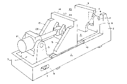
As seen in Figs. 1 and 2 of the drawings, a clamping
assembly for an injection moulding installation comprises a rigid,
elongated, rectangular base frame 1 constituting a positioning structure
having, at one end thereof, a pair of upwardly extending support posts 2.
An elongated, substantially rectangular clamping structure 3 nests within
the base frame 1 and comprises an elongated planar base portion 4 and,
at either end thereof, pairs of bearing posts 5 and 6. The end of the
clamping structure 3 adjacent the support posts 5 is formed with a pair
of laterally extending support pins 7 which extend through a pair of
5 ~088417
longitudinally extending slots 8 formed in the base frame 1 so that the
structure 3 is supported on the base frame 1 and is capable of limited
longitudinal displacement with respect thereto.
A fixed platen 9 is formed integrally with the support posts
2 and with a rearwardly extending lug 10. The latter is located between
the support posts 6 and is pivotally mounted with respect thereto by
means of an axle 11.
A movable platen 14 is formed with a pair of rearwardly
extending struts 15, the under edges of which rest on elongated ribs 16
integral with an upper edge of the base frame 1. These under edges of
the struts 15, together with the ribs 16, constitute sliding contact bearings.
A hydraulic drive piston 21 is pivotally mounted between
the posts 5 and has extending therefrom a piston drive rod 22 which
terminates in a head portion 23 which is pivotally mounted to and
between a pair of rearwardly extending lugs 24 formed integrally with
a rear surface of the movable platen 14.
The region between the fixed and movable platens 9, 14
constitutes an effective clamping region 25. The object to be clamped,
such as a two-piece mould (not shown), is located in the clamping region
25 and the hydraulic piston 21 drives the movable platen 14 towards the
object and exerts sufficient pressure on the object so as to maintain it
effectively and securely clamped.
It will be seen that whilst the fixed platen 9 is formed
integrally with the base frame 1, the movable platen merely rests on the
base frame 1 (and is therefore capable of linear translational displace-
ment with respect thereto). On the other hand, such translational
displacement of the movable platen, as a reaction to the forces acting
thereon consequent upon clamping of the object, is resisted by the
coupling of the movable platen 14, via the hydraulic piston 21, to the
support structure 3. In~consequence, this reaction does not give rise to
any distortion (due to bending or the like) in the base frame 1 and the
relative disposition of the fixed and movable platens remains substantial-
' - 6 - 20884~7
ly invariant. Any bending stresses acting on the clamping structure 3
merely results in a certain degree of bending of the latter without in any
way affecting the basic spacing between the platens. In point of fact, the
bending stresses induced in the clamping structure 3 are transmitted via
5 the pivotal coupling of the latter to the fixed platen 9 so as to ensure its
even firmer clamping of the object against the movable platen 14.
In an alternative embodiment shown in Figs. 3 and 4 of the
drawings, the clamping assembly is provided with a fixed platen 41 which
is formed integrally with a rigid, elongated rectangular base frame 42
10 constituting a positioning structure. A movable platen 43 is rigidly
coupled to a piston drive rod 44 of a hydraulic drive piston 45. The drive
piston 45 is held in a piston mounting bracket 46. Both the movable
platen 43 and the bracket 46 are slidably supported on the upper surfaces
of elongated ribs 47, the undersurfaces of the movable platen 43 and the
15 bracket 46, together with the upper surfaces of the ribs 47, constituting
sliding contact bearings.
A pair of clamping arms 48 (only one being seen) extends
longitudinally within the rectangular base frame 42 and adjacent a pair
of longitudinal sides thereof. One adjacent pair of upturned end portions
20 48a of the clamping arms 48 are respectively and pivotally coupled to
opposite sides of the mounting bracket 46 whilst an opposite pair of
adjacent upturned ends 48b of the clamping arms 48 are pivotally
coupled to the fixed platen 41.
In this embodiment, the movable platen 43 and the hydraulic
25 drive piston 45 form a unit which rests on the positioning structure (the
movable platen 43 being longitudinally slidable with respect to the
positioning structure. As in the previously described embodiment, the
reaction on the fixed and movable platens 41 and 43 as a result of
clamping pressure being exerted on the clamped object does not result in
30 any distortion of the positioning structure but, if anything, results in a
slight bending of the clamping arms 48. This does not, of course, affect
208~4~'~
the spacing between the platens 41 and 43 but merely results in the fixed
platen 41 being more firmly pressed against the clamped object.
In a still further embodiment, as shown in Fig. S of the
drawings, the clamping assembly is essentially simil~r to that described
S with reference to Figs. 3 and 4, with the sole exception that, whereas in
the assembly shown in Figs. 3 and 4 the clamping arms 48 (i.e. the
clamping structure) are located within the rectangular base frame 42 (i.e.
the positioning structure), in the assembly shown in Fig. S of the
drawings, the clamping arms 48' are located outside the base frame 42'
10 and respectively adjacent the outside longitudinal sides thereof. In this
way, the entire region between the platens and within the base frame 42'
remains unencumbered by the clamping structure.
Fig.6 of the drawings illustrates a clamping assembly of the
kind illustrated in Fig. S of the drawings, namely one wherein clamping
15 arms 48" are located outside a base frame 42", but in this case a
movable platen 43' is coupled to a hydraulic drive system 49 via a toggle
lever assembly 50. The drive system 49 is used to activate the toggle
assembly to displace the movable platen 43'. The toggle assembly 50
serves as a positive stop and pressure holding device during injection.
20 This type of assembly responds very quickly to opening and closing
displacements of the movable platen 43'.
The clamping assemblies in accordance with the invention,
as described with reference to the drawings, are capable of operating with
high clamping pressures without introducing any distortions in the
25 clamping region. It will be readily seen that with such an assembly
wherein the fixed and movable platens are not associated with tie bars,
the clamping region is readily accessible for the ready introduction and
removal of the mould and for the mechanical handling thereof.
In an embodiment of a clamping assembly in accordance
30 with a further aspect of the invention, as shown in Fig. 7 of the drawings,
the assembly includes a base frame 51 having an integrally formed fixed
platen 52 and a movable platen 53. The latter has integrally formed,
- 20~447
longitudinally extending support limbs 54 between which are mounted
sliding rollers 55 which slide in a longitudinally extending slot 56 formed
in the base frame 51, the rollers 55 and slot 56 constituting together
sliding contact bearings. The region between the platens 52 and 53
5 constitutes a clamping region 57, in which is shown located a two-piece
mould 58. Formed integrally with the end of the base frame 51 closest
the movable platen 53 is a support post 59 which has pivotally mounted
thereon a hydraulic piston 60 whose drive rod 61 is pivotally coupled to
the movable platen 53.
The sliding contact bearings, constituted by the rollers 55
and the slot 56, are substantially located outside the clamping region 57
and, in consequence, when clamping pressure is applied to the movable
platen 53 by the drive rod 61, the counteracting forces acting on the base
frame 51 via the support post 59 leads to the bending distortion of that
15 portion of the base frame 51 outside the clamping region 57 without
affecting the clamping region itself.
Whilst in the specific embodiments described above the
coupling of the fixed platen to the base frame, as well as the coupling of
the drive rod to the movable platen, have been by way of pivotal
20 couplings, it will be appreciated that other forms of coupling can be
employed which, while transmitting axially directed forces, nevertheless
allow for a limited degree of relative tilting motion between the coupled
components.