Language selection

Search

Patent 2088573 Summary

Third-party information liability

Some of the information on this Web page has been provided by external sources. The Government of Canada is not responsible for the accuracy, reliability or currency of the information supplied by external sources. Users wishing to rely upon this information should consult directly with the source of the information. Content provided by external sources is not subject to official languages, privacy and accessibility requirements.

Claims and Abstract availability

Any discrepancies in the text and image of the Claims and Abstract are due to differing posting times. Text of the Claims and Abstract are posted:

  • At the time the application is open to public inspection;
  • At the time of issue of the patent (grant).
(12) Patent Application: (11) CA 2088573
(54) English Title: METAL SECTION WITH AN OCTAGONAL CROSS-SECTION FOR WINDOW OR DOOR FRAMES
(54) French Title: PROFILE METALLIQUE AVEC SECTION TRANSVERSALE OCTOGONALE POUR LA FABRICATION DE CADRES DE PORTE ET DE FENETRE
Status: Deemed Abandoned and Beyond the Period of Reinstatement - Pending Response to Notice of Disregarded Communication
Bibliographic Data
(51) International Patent Classification (IPC):
  • E06B 7/14 (2006.01)
  • E06B 3/08 (2006.01)
  • E06B 3/12 (2006.01)
(72) Inventors :
  • ZANONI, EDOARDO (Italy)
(73) Owners :
  • HYDRO ALLUMINIO ORNAGO S.P.A.
(71) Applicants :
  • HYDRO ALLUMINIO ORNAGO S.P.A. (Italy)
(74) Agent: RICHES, MCKENZIE & HERBERT LLP
(74) Associate agent:
(45) Issued:
(86) PCT Filing Date: 1991-07-20
(87) Open to Public Inspection: 1992-02-01
Availability of licence: N/A
Dedicated to the Public: N/A
(25) Language of filing: English

Patent Cooperation Treaty (PCT): Yes
(86) PCT Filing Number: PCT/EP1991/001375
(87) International Publication Number: WO 1992002706
(85) National Entry: 1993-02-01

(30) Application Priority Data:
Application No. Country/Territory Date
21586 B/90 (Italy) 1990-07-31

Abstracts

English Abstract

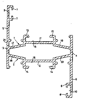
2088573 9202706 PCTABS00010
The section has a tubular shape with a substantially polygonal
cross-section, provided with two larger faces (1, 2) opposite to
one another and two smaller faces (3, 4) forming a connection with
said larger faces, which extend in abutment elements (5, 6)
suitable for defining with said larger faces the inner front and the
outer front, respectively, of the window or door frame. The two
larger faces (1, 2) comprise respective central portions (11, 12)
parallel to one another provided with flaps (13, 14) defining
C-shaped cavities (15, 16) for housing and connecting various members
of the window or door frame. Each larger face also comprises
lateral portions (17, 19; 18, 20) converging towards the
corresponding lateral portions of the other larger face until they connect
with the smaller faces. The section includes a hole (21) for
drainage purposes.


Claims

Note: Claims are shown in the official language in which they were submitted.

- 6 -
C L A I M S
1. Metal section for window or door frames, having a
tubular shape with a substantially polygonal cross-section,
provided with two larger faces (1, 2) opposite to one another
and two smaller faces (3, 4) forming a connection with said
larger faces, which extend in abutment elements (5, 6) suitable
for defining with said smaller faces (3, 4) the inner front and
the outer front, respectively, of the window or door frame,
said larger faces (1, 2) comprising respective central portions
(11, 12) parallel to one another provided with flaps (13, 14)
defining C-shaped cavities (15, 16) for housing and connecting
various members of the window or door frame, characterized in
that each of said larger faces (1, 2) also comprises lateral
portions (17, 19; 18, 20) converging towards the corresponding
lateral portions of the other larger face until they connect
with said smaller faces (3, 4).
2. Section according to claim 1, characterized in that at
the intersection between one abutment element (5) defining the
outer front of the window or door frame and the nearest (1) of
said larger faces (1) there is at least one hole (21) suitable
for allowing the infiltrated water to flow away.

Description

Note: Descriptions are shown in the official language in which they were submitted.


~ 92/02706 2 0 8 ~ ~ 7 3 PCr/EP91/Ot375
- 1 - .
"Metal section with an octagonal cross-section for winaow or
door frames".
The present invention relates to a metal section with an
octagonal cross-section for window or door frames.
The use is known of aluminium alloy metal sections for the
construction of window or door frames of various kinds, in
particular for external w;ndows.
It is also known that the same section may be used for the
fixed parts and for the movable parts of the window or door
frame.
As shown in the utility model application No. 21900 B/89
filed on 10 October 1989 in the name of the same applicant,
such a section has a tubular shape with a substantially
rectangular cross-section with two essentially flat larger
sides provided with respective pairs of outer flaps suitable
for defining respective C-shaped cavit;es for connecting parts
of a hinge to other members to be associated with the section,
and two smaller sides perpendicular to the previous ones, which
extend in abutment elements suitable for defining, with the
smaller sides themselves, the inner front and t~e outer front,
respectively, of the window or door frame.
Again according to the known art with two equal sections it
is possible to accomplish a connection of the traditional type,
that is with seals in turn of the traditional type, acting by
compression and housed in appropriate seats of the abutment
elements. The possibility is also provided for connecting one
of these sections to a section of a slightly different type for
accomplishing a connection of the open-joint type, that is with
the seal floating inside the window or door frame.
. ~ ' : ,,' , ~ .-
'

~ ~ .
2 0 8 8 5 ~ 3 PCr/EP9l/UI3
In the traditional solution the stagger between the t~o
abutment elements ;s used to house the seals, while in the
open-jo;nt solution there is a substantial coplanarity of the
outer sides and a variable seal is arranged in an internal
space between the two sections.
In both cases there can be an input of water which
stagnates ;nside the w;ndow or door frame w;thout it being
possible to cause it to flow away.
The o~ject of the present invention is to overcome such a
1D drawback with a metal section shaped so that any water that has
;nfiltrated between the fixed part and the movable part of the
frame can be eliminated immediately.
According to the invention such object is attained with a
metal section for window or door frames, having a tubular shape
with a substantially polygonal cross-section, provided with two
larger faces opposite to one another and two smaller faces ;
forming a connection with said larger faces, which extend in
abutment elements suitable for defining with said smaller faces
the inner front and the outer front, respectively, of the
window or door frame, said larger faces comprising respective
central portions parallel to one another provided with flaps
defining C-shaped cavities for housing and connecting various
members of the w;ndow or door frame, characterized in that each
of said larger faces also comprises lateral portions converging
towards the corresponding lateral portions of the other larger
face until they connect with said smaller faces.
At the intersertion between said smaller face defining the
outer front of the window or door frame and sa1d first larger
face there is at least one hole su;table for allowing any water
that may have infiltrated to flow away.

~ 92/02706 2 0 8 8 5 7 3 PCI`/EP91/01375
. , - . ; .,
3 --
In such way the presence of the inclined lateral portions
allows the formation of a kind of small lateral reservoir in
which any water that may have infiltrated is invited to collect
and then to flow away through the above hole. Water will thus
be prevented ~rom st~gnating inside the w;ndow or door frame.
The feae~res of the present invention shall be made more
ev;dent by the foLlowing detailed description of an embodiment
illustrated as a non-limiting example in the enclosed drawings,
wherein:
Fig. 1 illustrates a metal section according to the
invention;
Fig.s 2, 3 ;lLustrate respective methods of utilization of
the metal section according to the invention, with the
traditional solution with a seal and with the open-joint type,
respectively.
With reference to Fig. 1, the metal section according to
the invention is configured with a tubular shape having a
substantially po~ygonal cross-section with a f;rst and a second
larger face 1, 2 opposite to one another and two smaller faces
2û 3, 4 forming a connect;on between the two larger faces 1, 2,
which extend in abutment elements 5, 6 suitable for defining
with the same smaller faces 3, 4 the inner front and the outer
front of the window or door frame. The abutment elements 5, 6
have respective pairs of opposite flaps 7, 8 suitable for
defining smaller cavities 9, 10. The first and second larger
faces 1, 2 comprise central portions 11, 12 parallel to one
another provided with flaps 13, 14 defining C-shaped cavities
15, 16 for the purposes which shall be explained later. The
f1rst larger face 1 also comprises lateral portions 17, 19
converging towards corresponding lateral portions 18, 20 of the
- . . . : '

WO 92/02706 PCr/EP91/013~ 1,
2o88a73 _ 4_
second larger face 2. On the abutment element S, at the
intersection with the larger face 1, there are holes 21 for the
purposes which shall be explained later.
As illustrated in Fig. 2, according to the traditional
connection two sections A and ~ identica~ with that o~ F;g~
are used for the fixed part and for the movabLe part of the
window or door frame. For the fixed part a section A is
fastened in a way known in itseLf to the jamb, not shown, and
to the fixed part 22 of a hinge 25. According to such a
solution an identical section B holding a pane of glass 24 with
the help of an eLement 40 holding the pane of glass receives ;n `/
the C-shaped cavity 16 of the larger face 12 a connecting -
element 28 for the movable part 41 of the hinge 25. Between
the a~utment elements 6 of the two sections A and ~ there is
defined a space suitab~e for the passage of the fixed and
movable parts 22 and 23 of the hinge 25 and for the housing of
a seal 26 inserted in the cavity 1û of the section B, while
between the abutment elements 5 of the same sections there is
defined the space necessary for the housing a seal 27 inserted
in the cavity 9 of the section A.
Due to the effect of the convergence of the lateral
portions 17 and 18 of the section A, any water that may have
infiltrated through the seal 27 is collected in a small
reservoir SO formed by the inclination of the above portion 17
so that it may later be made to flow through the hole 21 of the
same section A.
As illustrated in Fig. 3, an open-joint connection implies
the use of a section A in combination with a slightly different
section. There occurs in this case a coplanarity of the
abutment elements S of the sections A and C at the outer front

~ 92/02706 2 0 8 8 ~ 7 3 ~
.
5 --
of the window or door frame and a variable seal 29 is arranged
in an internal space between the two sec~,ons A, C, defined by
a tang 41 of the section C and a nearby flap 13 of the section
A.
Any water that may have penetrated through the passage
between the extension 5 of the smaller side 3 of the section A
and that of the section C is collected in a small reservoir 52
created by the seal 29 to be then d;scharged through the hole
21 in a manner altogether similar to that illustrated
previously.
.
- . ~ "
:

Representative Drawing
A single figure which represents the drawing illustrating the invention.
Administrative Status

2024-08-01:As part of the Next Generation Patents (NGP) transition, the Canadian Patents Database (CPD) now contains a more detailed Event History, which replicates the Event Log of our new back-office solution.

Please note that "Inactive:" events refers to events no longer in use in our new back-office solution.

For a clearer understanding of the status of the application/patent presented on this page, the site Disclaimer , as well as the definitions for Patent , Event History , Maintenance Fee  and Payment History  should be consulted.

Event History

Description Date
Inactive: IPC from MCD 2006-03-11
Time Limit for Reversal Expired 1999-07-20
Application Not Reinstated by Deadline 1999-07-20
Deemed Abandoned - Failure to Respond to Maintenance Fee Notice 1998-07-20
Inactive: Abandon-RFE+Late fee unpaid-Correspondence sent 1998-07-20
Application Published (Open to Public Inspection) 1992-02-01

Abandonment History

Abandonment Date Reason Reinstatement Date
1998-07-20

Maintenance Fee

The last payment was received on 1997-06-05

Note : If the full payment has not been received on or before the date indicated, a further fee may be required which may be one of the following

  • the reinstatement fee;
  • the late payment fee; or
  • additional fee to reverse deemed expiry.

Please refer to the CIPO Patent Fees web page to see all current fee amounts.

Fee History

Fee Type Anniversary Year Due Date Paid Date
MF (application, 6th anniv.) - standard 06 1997-07-21 1997-06-05
Owners on Record

Note: Records showing the ownership history in alphabetical order.

Current Owners on Record
HYDRO ALLUMINIO ORNAGO S.P.A.
Past Owners on Record
EDOARDO ZANONI
Past Owners that do not appear in the "Owners on Record" listing will appear in other documentation within the application.
Documents

To view selected files, please enter reCAPTCHA code :


To view images, click a link in the Document Description column. To download the documents, select one or more checkboxes in the first column and then click the "Download Selected in PDF format (Zip Archive)" or the "Download Selected as Single PDF" button.

List of published and non-published patent-specific documents on the CPD .

If you have any difficulty accessing content, you can call the Client Service Centre at 1-866-997-1936 or send them an e-mail at CIPO Client Service Centre.


Document
Description 
Date
(yyyy-mm-dd) 
Number of pages   Size of Image (KB) 
Abstract 1992-02-01 1 48
Cover Page 1992-02-01 1 22
Drawings 1992-02-01 2 64
Claims 1992-02-01 1 28
Abstract 1992-02-01 1 63
Descriptions 1992-02-01 5 150
Representative drawing 1998-07-29 1 8
Reminder - Request for Examination 1998-03-23 1 118
Courtesy - Abandonment Letter (Maintenance Fee) 1998-08-17 1 189
Courtesy - Abandonment Letter (Request for Examination) 1998-08-31 1 173
Fees 1997-06-05 1 42
Fees 1996-05-17 1 44
Fees 1994-06-17 1 45
Fees 1993-02-01 2 64
Fees 1995-06-07 1 43
International preliminary examination report 1993-02-01 9 304
Courtesy - Office Letter 1993-04-07 1 27