Note: Descriptions are shown in the official language in which they were submitted.
2088616
IGNITION PERFORMANCE MONITOR AND MONITORING
METHOD FOR CAPACITIVE DISCHARGE IGNITION SYSTEMS
This invention relates to ignition system
monitoring units generally, and more particularly to an
ignition performance monitor for monitoring the
performance of a spark ignited engine which employs a
capaciti~re discharge ignition system.
A number of monitoring systems for spark ignited
engines have been developed in an attempt to
effectively detect engine misfiring before engine
performance deteriorates significantly. It has been
found that the functioning of the engine ignition
system can be tested to indicate an abnormal engine
condition,'such as a fouled or defective spark plug, an
improperly balanced engine or a defective engine
component associated with a particular cylinder. Such
testing method s have proven to be particularly
effective for monitoring spark plug condition, since
this condition directly affects the function of the
ignition system.
Many ignition system monitoring units measure a
voltage characteristic occurring at the secondary
winding of an ignition coil, and some of these systems
are invasive and must be manually attached to the
secondary winding. The voltage signal amplitude at the
. secondary.winding is much greater than that of the
signal at the primary winding, and these systems must
perform the difficult task of accurately monitoring the
- 1 -
2088616
high secondary voltage characteristic without
disrupting the normal operation of the ignition system.
Secondary voltage monitoring systems are shown by U.S.
Patent Nas. 3,793.584 to L.N. Liebermann et al.,
3,942,102 to K.L. Kuhn et al., 4,006,403 to M. Olsen et
al., 4,558,280 to S.E. Koehl et al., and 4,547,734 to
H-W Spaude.
U.S. Patent No. 4,277,752 to W. Dinkelackey et al.
discloses a device for testing the ignition system of a
combustion engine which includes an adjustable load
connected in the primary winding of the ignition coil.
The load is progressively increased until an ignition
slip or misfire is detected, and from this,' ignition
energy reserve can be calculated to provide a measure
1S for the condition of the whole ignition system.
Although this system works from the primary winding of
the ignition coil, it is very intrusive and can
function only by intentionally causing a misfire. Thus
no indication is provided of the performance of the
ignition system under actual operation conditions.
Systems have been developed for monitoring voltage
characteristics at the primary winding of an ignition
coil during actual engine and ignition system operating
conditions, and systems of this type are disclosed by
U.S. Patent Nos, 4,684,896 to w. Weishaupt and
4,918,389 to R. Schleupen et al. These patented
systems rely upon waveform characteristics which are
only present in inductive type ignition systems and
which are not found in capacitive discharge (CD) type
ignition systems. The peak primary voltage of a
capacitive discharge ignition system is fixed, while
the peak primary voltage of an inductive type ignition
system varies. as a function of the peak firing voltage
(secondary voltage). Also, spark duration cannot
readily be determined from the primary voltage waveform
- 2 -
2088616
for a capacitive discharge ignition system, while the
spark duration is easily determined from the primary
voltage waveform in an inductive ignition system.
The misfire detection system and method of the
Schleupen patent relies upon the extraction of spark
duration information from the voltage in the primary
winding of an ignition coil and the comparison of this
information with a reference voltage of a predetermined
magnitude and duration. The testing method and
apparatus of the Weishaupt patent relies upon the peak
primary voltage of an ignition coil being a function of ..
the peak firing voltage to calculate spark plug
condition. Thus neither of these systems will operate
with a capacitive discharge ignition system.
Di~c~oSure of the Inventi,QD
It is a primary object of the present invention to
provide a novel and improved ignition performance
monitor for capacitive discharge ignition systems which
provides measurements on a real-time basis during the
operation of an internal combustion engine.
Another object of the present invention is to
provide a novel and improved ignition performance
monitor far capacitive discharge ignition systems which
operates from waveform characteristics which are
present in capacitive discharge ignition systems and
which does not adversely affect normal system
operation.
Yet another object of the present invention is to
provide a novel and improved ignition performance
monitor for ~apacitive discharge ignition systems which
takes a measurement on the primary side of an ignition
coil and which has the capability of monitoring up to
sixteen ignition coils simultaneously so that all
- 3 -
2088fi16
engine cylinders are simultaneously monitored.
A further object of the present invention is to
provide a novel and improved ignition performance
monitor for capacitive discharge ignition systems which
measures the rate at which the magnetic field of the
ignition coil collapses (i.e. current in the primary
winding goes to zero) to obtain a relative indication
of the voltage required to fire a spark plug.
A still further object of the present invention is
to provide a novel and improved ignition performance
monitor for capacitive discharge ignition systems which
senses the flux density generated by current flowing
through the primary side of an ignition coil. A pulse
is then generated with a pulse width equal to the time
that the current is above zero amps, and this time is
measured to provide data from which the secondary
voltage of the ignition transformer is computed.
These and other objects of the present invention
include the provision of a novel and improved ignition
performance monitor which operates effectively with the
fixed peak primary ignition coil voltage provided by a
capacitive discharge ignition system. Since this
primary voltage is fixed, the monitor cannot employ a
voltage reference signal indicative of a normal firing
voltage as a reference for determining ignition system
and engine condition. Consequently the monitor of the
present invention employs a current measurement to
measure the collapse of the magnetic field in an
ignition coil by determining the time that the current
through the primary winding of the ignition coil
remains above a zero ampere level. A toroidal coil is
provided between the output of a capacitive discharge
' ignition -unit- and the primary winding of an ignition
coil to concentrate flux density into a small cross
sectional area so that the flux density can be measured
- 4 -
208861
bY a Hall Effect sensor. The output signal from the
Hall Effect sensor is compared with a signal indicative
of a zero ampere current level in a comparator, and the
time duration of the comparator output is measured.
This time duration measurement is used to produce an
indication of the ignition coil secondary voltage
required to fire a spark plug.
$r~ DescrinrWn a the DraWlnQc
Figure I is a block diagram showing the Ignition
Performance Monitor for Capacitive Discharge Ignition
System of the present invention;
Figure 2 is a flow diagram of the initialize
procedure performed by the processor for the ignition
performance monitor of Figure 1;
Figure 3 is a flow diagram of the main loop
procedure performed by the processor for the ignition
performance monitor of Figure 1; and
Figure 4 is a flow diagram of the interrupt
procedure 'performed by the processor for the ignition
performance monitor of Figure 1.
Best Mode for Carrv~ nor n"r rhA Tn r
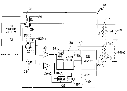
Referring now to Figure 1, the ignition
performance monitor of the present invention indicated
generally at 10 is connected between a capacitive
discharge ignition system 12 of a conventional type and
ignition coils l4,and 14(n) which operate in a
canventiohal manner in response to pulses from the
ignition system to fire spark plugs 18 and 18(n). Only
two ignition coils and spark plugs are illustrated in
Fig. 1 for purposes of example, but in actuality, the
ignition performance monitor 10 is capable of operating
- 5 -
208616
simultaneously with up to sixteen ignition cods and
spark plugs, so the ignition coils 14(n) and the spark
plugs 18(n) represent. up to fifteen of these
components. Thus, the ignition performance monitor is
capable of simultaneously monitoring the performance of
each cylinder of a spark ignited engine, and an
aperator can quickly compare cylinder-to-cylinder
operation to determine if any abnormal conditions
exist.
Each of the ignition coils 14 and 14(n) includes a
primary winding 22 and a secondary winding 24 which is
connected to an associated spark plug. The~ignition
performance monitor 10 includes a toroidal winding 26
Which is connected in series between the output from
the capacitive discharge ignition system 12 and the
primary winding 22 of an ignition coil. Since the
ignition performance monitor circuit for each ignition
coil is the same, one such monitor circuit channel will
be described herein and the same reference numerals
combined with an indicator (n) will be applied to like
elements in the remaining monitor circuit channels to
identify a plurality of identical channels.
The torroidal coil 26 receives the current output
from the capacitive discharge ignition system 12 and
concentrates the flux density resulting therefrom into
a small cross-sectional area. This permits a Hall
Effect sensor 28 to measure this flux density, and
changes in the flux density are generated by the
current. flowing through the primary 22 of the
respective ignition coil. The Hall Effect sensor 28
provides an putput voltage proportional to this primary
current, .and this voltage is connected to a low pass
filter 30 to remove any unwanted high frequency signal
components. The filtered output from the low pass
_ 6 _
2p8g6~6
filter is then; fed o t~, voltage comparator: 32 where. it
is compared to a reference voltage from a reference
source 33 that is proportional to a current of zero
amperes.
The reference voltage from the source 33 is
provided to the inverting input of the comparator 32
while the filtered output signal from the filter 30 is.
provided to the non-inverting .input..of-the comparator
The comparator switches from'a first'state to avsecond .
state depending upon the relatio~iship of-.the signals at
its two inputs, and conseQuently, will provide an
output pulse that has a duration (pulse width)~;equal to
the length of time that the primary current through an
associated primary winding 22 is above zero amps. The
output of the comparator is connected to one of a
plurality of timing registers 34 in a microprocessor
36, and a timing register is provided to receive the
output from each of the comparators 32. Each timing
register measures the time of the pulse from a
comparator,~32 which indicates the period during which
the primary current is above zero amps. The timing
register provides the microprocessor with a signal
indicative of this time, and the microprocessor employs
this time signal to mathematically produce an output
indicative of the secondary voltage in the secondary
winding 24 of an ignition coil available to fire an
associated spark plug. This output indication from the
microprocessor is displayed by any suitable display
unit 38 such as a graphic LCD display module.
when the comparator 32 switches state at the end
of an output pulse to indicate that the current through
a primary winding 22 is no longer above zero amps, an
' interrupt~signal will be provided by a reset signal
generator 39 to the microprocessor 36. Upon receiving
this i_r:terrupt si gr:c~ , thc:~ mi.croproces:;or will : eac the
_ , _
2088616
number of clock cycles that have accumulated ir. the
timing register 34 during the duration of the pulse
width from the comparator. The microprocessor will
then zero the timing register in anticipation of the
next pulse width to be measured, will scan all channels
to determine which one caused the interrupt signal, and
will store the clock cycle number from the timing
register in a memory location reserved for that
channel.
The ignition coils which may be used for the
ignition coils 14, 14(n), can be of different types,
and each type of ignition coil has a characteristic
slope (M) which will affect the rate at which the
magnetic field of the ignition coil collapses as well
as a unique characteristic represented by a constant
(B). Consequently, the microprocessor 36 must be able
to access information pertaining to the specific type
of ignition coil connected to the capacitive discharge
ignition system 12.
A suitable input unit 40 is connected to the
microprocessor 36 to provide informatior_ to the
microprocessor indicative of the type of ignition coils
which form the ignition coils 14 and 14(n). This input
could constitute a series of DIP switches which will be
set to appropriate positions by an operator to identify
an ignition coil type for each channel. Alternatively,
the input 40 might constitute a serial port through
which an ignition coil identifier is communicated to
the microprocessor by means of a keyboard or other
input unit. The identifier information from the input
is then stored in an EEPROM 42.
The microprocessor 36 will process the pulse width
measurements~(FW? taken from the timing register 34
based upon the type of ignition coils being used in the
35 channel involved, in general, the secondary voltage
_ g _
208866
ticV) in the involved ignition coil will be de~er:tiired
by the formula:
KV = M x PW + B
Since the slope (M) and the constant (B) are
characteristic of the type of coil used, this
information will be provided to the microprocessor from
the EEPROM 42 and once the secondary voltage is
computed, the data is formatted and displayed on the
display 38.
The operation of the microprocessor 36 may best be
understood by referring to the flow diagrams of Figures
2-4. when power is provided to the ,ignition
performance monitor 10 to start the microprocessor at
44, the microprocessor will initialize all memory
locations and registers at 46. It will then make a
determination at 48 as to what type of ignition coils
are being used in each channel to fire the respective
spark plugs 18 and 18(n). Normally, the same type of
ignition coil will be used in every channel, and when
this is the case, only a single coil type identified by
the input 40 is sensed at 48 and registered at 50 to
identify the slope and constant information for this
specific coil type for all channels.
It is, of course, possible for different types of
coils to be present in some of the channels, and if
this is the case, the input 40 is operative to provide
both a coil type indicator as well as a channel
indicator. When this is sensed at 48, the coil types
are registered in separate registers at 50 for each
channel, so when that channel is sequenced by the
microprocessor, the slope and constant information for
the coil used in that channel is provided.
' Once- the~ coil type is sensed and registered, the
microprocessor initializes the display 38 at 52 and
begins main loop operation at 54.
_ g _
~U~~36:~b
For main loop operation, the microprocessor
sequences through the channels at 56 to obtain a
measurement for each channel. When a channel is
sequenced, the last stored output pulse data from the
timing register 34-34(n) for that channel is obtained
at 58, while the registered coil type data for this
specific channel is obtained at 60. At 62, this data
is combined to compute the secondary voltage for the
coil type present in the channel. Then, at 64, the
last stared average secondary voltage data is obtained,
and this is averaged at 66 with the most recent w
secondary voltage data computed at 62. This new
average secondary voltage is stored at 68 in a memory
location dedicated to the channel involved, and will be
employed in the next average secondary voltage
computation for this channel. Also, the new average
secondary voltage data is formatted for display at 70,
and the display 38 is updated at 72. Then the main
loop is caused at 56 to sequence the next channel to be
reviewed.
The ignition performance monitor 10, when
energized, continuously takes measurements on all
channels during the operation of the capacitive
discharge ignition system 12. As previously indicated,
each channel, at the end of a measurement, causes a
reset or interrupt signal to be provided from a reset
signal generator 39-39(n) to the microprocessor 36. As
illustrated in Figure 4, when the microprocessor
receives an interrupt signal at 74, it first determines
the channel which is causing the interrupt at 76. The
microprocessor will then read the data stored in the
timing register 34-34(n) for this channel and will then
' zero and restart this register as indicated at 78. ~ The
data read from the register will be stored at 80 for
subsequent use in the main loop computation, and the
- 10 -
2088616
interrupt cycle will be ended at 82.
In some cases, it may be desirable to program a
set point value into the, microprocessor 36 which is
compared with each secondary voltage value computed at
62. If the secondary voltage calculated at 62 exceeds
the set point, then an alarm function can be activated.
The ignition performance monitor 10 takes
measurements in real-tune during the operation of an
internal combustion engine without interruption of I'
normal engine performance. The monitor has the
capability of monitoring the operation of a plurality
of engine cylinders at one time and will indicate
abnormal conditions to a user.
- I1 -