Note: Descriptions are shown in the official language in which they were submitted.
~0~8~6
Article of Clothinq, in pa~ticular
for the Medical or Chemical Field
-
The present invention is a continuation in part of US
Application Serial Number 07/86~ 839 (hereinafter the parent
application) and the di~closure of that application is being
repeated here to facilitate a better understanding of the
present invention. The invention of the parent application
relates to an article of clothing, in particular for the
medical or chemical field for protection against liquids
and/or micro-organisms, the article of clothing comprising
at least three layers, at least in part.
Articles of clothing which consist of at least three layers
are known, for example from the field of sport. Although
such articles of clothing are entirely suitable for the
intended uses and, for example, offer protection against
rain and wind, but are nevertheless able to breath actively
so that a requisite degree of comfort for the user is
achieved, they are not straightforwardly usable for some
important speci~ic applications in the medical and chemical
fields, for example, because of restrictions on their
ability to be sterilised.
It is required of such articles of clothing, which are
preferably worn by people who are active in the medical or
chemical fields, that they, on the one hand, offer a high
level of comfort to the wearer even over a long period of
time and, on the other hand, form a reliable barrier for
substances such as, for example, liquids and micro-
organisms, in particular bacteria.
,, .
,
:
~ ,
2 ~
With these articles of clothing it can sometimes happen that
substances pass through the article of clothing at
particularly stressed positions, i.e. at critical positions
which enter into intensive contact with the substances, such
as the blood of patients under applied pressure.
Thus the object of the parent application and also the
present invention is to provide an article of clothing which
is preferably usable in the medical or chemical field and
which e~fectively prevents the passage of substances, in
particular liquids such as blood, and micro-organisms, in
particular bacteria, through the article of clothing over an
adequately large period of time, without the article of
clothing however becoming uncomfortable to wear, and without
the freedom of movement of the wearer being restricted. Not
only gowns and overalls are regarded as articles of clothing
within the sense of the invention but rather also shoes,
gaiters, caps and the like.
In accordance with the parent application this object is
satisfied in an article of clothing of the initially named
kind, in that an outer layer is formed of a tightly woven
hydrophobic fabric which forms a liquid barrier and a micro-
organism barrier; in that an inner layer comprises a
material which likewise forms a liquid barrier and a micro-
organism barrier and is preferably likewise hydrophobic; and
in that an intermediate layer separates the outer layer and
the inner layer, at least at one critical position, and
pre~ents a direct contact of these layers.
Through the fact that the article of clothing, which can for
example be a surgical gown or an overall ~sed by a medical
rescue orderly, comprises at least three layers, at least in
part, it is possible to increase the time which is required
2~3~
-- 3
for liquid to pass ~ully through the article of clothing to
a considerable degree, in particular at stressed positions.
The first and outer layer, which stands in direct contact
with the substance, for example a liquid or a liquid
containing micro-organis~s, consists of a hydrophobic
material which is closely woven from endless filaments and
thereby forms the main protection for the wearer as a result
of its characteristics, with barriers for bacteria and
liquid. If a substance succeeds in passing through the first
and outer layer of the article of clothing it will then
encounter the intermediate layer. Passage of the substance,
for example, a liquid through the outer layer can be caused
when the wearer of the article of clothing is in
particularly pronounced contact with the substance. This
can, for example, arise if the wearer is carrying out
actions in the interior of a body during an operation, or if
the outer layer of the article of clothing comes into
contact with the substance under substantial pressure and
over a longer period of time through support of the elbow on
a liquid contaminated substrate.
~.
Through this intermediate layer, which effectively prevents
direct contact of the outer and inner layers it is ensured
that the further movements of the substance or the liquid in
the direction of the inner layer is counteracted. As a
result of the intermediate layer the substanc~ is forced to
select the path of least resistance and to re-distribute
itself in the intermediate layer, i.e. in directions
approximately perpendicular to the direction of penetration.
If an intermediate layer were not present then the contact
pressure ~ould lead to a wetting of the outer and inner
layers with the substance so this substance could relatively
quickly penetrate both layers at the positions of contact.
. . . ~, .
2~8~$~
The construction of the invention e~fectively prevents the
passage of the substance through the entire fabric over a
period of time which can be much more than twice the time
which was required in order to penetrate only one layer.
Furthermore, the types of fabric used are capable of active
breathing so that, for example, sweat given off by the body
of the wearer of the clothing can pass in the form of water
vapour through the article of clothing at any time into the
environment, whereby condensation inside the clothing is
effectively prevented and the comfort of the wearer is
increased. The fact that the intermediate layer is only
provided in critical regions of the article of clothing
means that the remaining regions can be of lighter
construction, whereby the comfort to the wearer is further
increased.
Furthermore, the design of the article of clothing in
accordance with the invention ensures that the freedom of
movement of the wearer is not restricted. This is, for
example, of great significance with regard to the scope of
movement required for an operation which extends over a
longer period of time.
For the purpose of pleasant and comfortable wearing of the
article of clothing provision is made, in an advantageous
embodiment, that the inner layer is of lighter design than
the outer layer. This is also made possible by the fact that
the inner layer which does not come into direct contact with
the environment is subject to substantially less stress than
the outer layer.
In a further advantageous embodiment the seams`which are
present for the various layers are preferably displaced
:
.
'.
,
~3~
-- 5
relative to one another. In this way it is ensured that an
easy path through the article of clothing is not offered to
liquid or bacteria via the stitches of two seams which lie
on top of one another. If a liquid should for example
succeed in passing through the outer layer then it will
encounter the intermediate layer and will only contact the
inner layer at a later time, if at all. As the inner layer
does not have a seam at this position its liquid and
bacteria blocking characteristics come fully into play and
prevent passage through the article of clothing.
Furthermore, attention is preferably paid to the fact that
the seams are not arranged in regions in which critical
positions are defined. This embodiment takes account of the
fact that the substances are hindered less in passing
through the seam positions than they are in passing through
the individual layers.
In a f~rther advantageous embodiment the intermediate layer
has a grid-like or net-like structure which is preferably
woven and consists of non-absorbent material. A substance
which passes through the outer layer, for example, a liquid
can flow without great resistance in directions
perpendicular to the penetration direction, through
interconnected receiving volumes which are formed between
the meshes, from one receiving volume to the next, for
example, as a result of the applied contact pressure. The
substance is thus distributed in the intermediate layer and
stored in the receiving volumes. After use the article of
clothing is cleaned with the substance being removed from
the receiving volumes. This succeeds despite the hydrophobic
characteristics of the outer or inner layers because the
surface tension of the washing liquid is set to a lower
value during washing which makes wetting of the fabric
possible.
2 ~
-- 6 ~
In a further advantageous embodiment the intermediate layer
consists of absorbent material, ~or example foam, however
preferably of woven material with the fabric filaments being
absorbent. The intermediate layer picks up the substance
which passes through the outer layer. A further force must
now be e~pended, additional to the force which is necessary
to press the substance through the inner layer, in order to
press the substance out of the intermediate layer. In this
way the article of clothing as a whole becomes more
impenetrable.
In accordance with a further advantageous embodiment the
passage of substances through the article of clothing is
fully prevented by an impermeable layer. However this layer
should not be provided over the entire article of clothing
because otherwise a disadvantage arises that the article of
clothlng is no longer capable of breathing.
The impermeable layer can preferabIy be provided in addition
to the net-like or absorbent intermediate layer at
particularly critical positions, for example in the elbow
region, by which it is ensured that the penetration of
substances at precisely the critical positions is
effectively prevented, without however having to completely
line the entire article of clothing with an impermeable
layer. The net-like or absorbent intermediate layer thereby
also provides take-up capacity for the liquid which
penetrates the outer layer.
In a further advantageous embodiment a carrier layer is
arranged between the outer and inner layers and is
preferably formed in grid-like manner with a relatively
large grid spacing. An intermediate layer can be mounted at
the particularly critical regions onto this carrier layer.
The carrier layer can be present throughout the entire
article of clothing because it is not particularly
noticeable. In this arrangement it is of particular
advantage that the carrier layer does not have to be secured
at the critical positions, thus it is, for example, possible
to apply an impermeable layer at a desired position without
having to use seams at the critical positions, since the
impermea~le layer is carried at the critical positions by
the carrier layer.
In accordance with the present C.I.P. application
a further solution of the principal object underlying the
present invention is achieved by an ar-ticle of clothing
comprising at least inner and outer layers, at least in
part, the article of clothing being characterised in that
the outer layer is formed of a tightly woven hydrophobic
fabric which forms a liquid barrier and a micro-organism
barrier; and in that the inner layer comprises at least one
carrier material having a net-like apertured or open mesh
structure secured or securable to said outer layer at at
least one position ~hich is less susceptible to the ingress
of liquids and/or micro~organisms, in particular at side or
back seams or at the shoulder and cuff seams of a gown, and
in that at least one membrane is secured to said carrier
material at least one critical position at which the danger
exists of the passa~e of liquids and/or micro-organisms
through said outer layer.
In this embodiment there are thus a minimum of two layers in
distinction to the three layers of the previous embodiments.
The carrier material or fabric serves a multiple function in
this alternative solution. On the one hand the carrier
material serves, as previously, to position the membrane so
'
.
2 ~
-- 8
that this covers critical regions of, for example, a
surgeons gown. Such critical regions typically comprise the
trunk and abdomen regions and the arms. ~t the same time the
carrier material, by virtue of its net-like, apertured or
open mesh structure permits a relati~ely free flow of air
within and into and out of the space between the outer layer
and the membrane and thus greatly improves the com~ort of
the gown so far as the surgeon or wearer is concerned. More
particulaxly it is envisaged that the movements which
inevitably take place during use of the gown arising from
actions of the wearer will generate a type of pump action
between the two layers which are movable relative to one
another, at least towards and away from each other so that
this pump action will itself induce an air flow between the
ou~er layer and the membrane and onto and around the
wearer's body which will also improve the degree of comfort
for the wearer.
The openinys in the carrier material also have the decided
advantage that they greatly facilitate the cleaning and
sterilisation of the article because the cleaning or
sterilising fluid e.g. steam then has ready access to the
inside of the outer layer and to the surface of the membrane
confronting the same.
The carrier material is preferably made as a resiliently
extensible and flexible layer so that the general stiffness
of the gown is reduced and again the gown is more
comfortable for the wearer.
Several different realisations of this basic concept of the
invention are possible.
~ore specifically the carrier material may extend behind the
2~3~
g
membrane on the side remote from the outer layer and may
form a laminate together with this membrane. In this case
the membrane could be stitched at its edge to the carrier
layer or could be adhesively bonded thereto at its edge, or
over its full area, or only at discrete regions.
Alternatively, the carrier material can be provided with an
opening at the position at which the membrane is arranged
with the membrane being secured to the carrier material, for
example at its marginal edge around the opening. This
connection can take place by stitching without any
particular precautions since the apertured carrier material
is in any case not a barrier to contaminated liquid and
fluid. It will be understood that the membrane is chosen to
be of a sufficient extent and arranged so that it extends in
all directions beyond locations at which the direct
penetration of liquid and/or micro-organisms through the
outer layer is to be feared.
As indicated previously the membrane can for example be
arranged in the trunk and abdomen regions of the gown in
which case it conveniently comprises an essentially planar
sheet material. Alternatively or additionally such membranes
can be provided in one or both arms of the gown. In this
case the or each membrane comprises a tubular structure and
is typically secured to the gown by said carrier material at
at least one of the cuff or shoulder regions of the sleeve.
~he use of a highly air-permeable carrier material at the
shoulder region ensures good ventilation at the wearer's
armpits which again improves the comfort of the gown. A
similar beneficial effect is achieved at the wrist of cuff
re~ion. Although it might appear that the use of a carrier
material which is naturally not only permeable to air but
also to liquid is undesirable at the cuff region it should
2 ~
-- 10
be pointed out that the cuff regions are covered by gloves
in use, so that there is already added protection in this
area against the penetration of contaminated liquid. Hence
the use of an air-permeable carrier material at this
location can be realistically considered. If particular
worries exist in this area then the use of the carrier
material can be restricted to the shoulder region. Indeed it
is conceivable that the membrane of the sleeve insert could
be attache~ at only one end to the gown, preferably at the
shoulder end to facilitate entry into the gown.
The or each membrane can be permanently secured within the
article of clothing or can be removably secured therein.
This can take place either by releasable securing means
connecting the membrane to the carrier material or by
releasable securing means connecting the carrier material to
the outer layer. Any of the conventionally used connecting
means can be considered, for example a Velcro-type fastener
tTM), a press stud fastener or indeed a zip fastener.
The use of removable membranes, or removable inner layers,
has the advantage that for some categories of operation
where contaminated liqùids or excessive amounts of liquids
or body fluids are not to be expected the inner layer can be
omitted altogether so that the wearer has an altogether
lighter and more comfortable gown. Moreover, the
sterilisation of the gown can in this way be further
improved. In addition only a limited variety of sizes of
membrane need be made which can be used with a larger
variety of gown sizes used for the outer layer material.
This can simplify storage and stock holding facilities.
Moreover, should either the outer layer or the inner layer
become damaged it can be replaced without having to replace
the whole gown. Stock holding is also facilitated in this
2 ~
way.
The membrane can be realised in various ways. For example it
can comprise a liquid-impermeable but water vapour permeable
material, for example a foil or textile material, or it may
comprise a material impermeable to both water and
water vapour. It is also possible to realise the membrane as
a composite membrane comprising at least first and second
layers with the first layer being disposed adjacent the
outer layer and the second layer being disposed on a face of
the first layer remote from the outer layer. In this case
the first and second layers can comprise the following
material pairs:
a) a liquid and water vapour impermeable foil as a first
layer and an open mesh woven or non~woven fabric as a
second layer, with an absorbent layer optionally being
provided on at least one face of said first layer,
b) a liquid-impermeable but water vapour permeable foil-like
membrane as a first layer and an open mesh woven or
non-woven fabric as a second layer, again with an
absorbent layer optionally being provided on at least one
face of said first layer.
Further advantageous embodiments are defined in the
subordinate claims.
The invention will now be described in more detail in the
following with reference to the drawings in which Figs. 1 to
8 comprise Figures 1 to 8 of the parent application US SN
07j864 839 and Figs. 9 to 15 relate to the invention of the
present C.I.P. application. An understanding of the
invention of Figs. 1 to 8 is useful for an understanding of
.
2 ~ 6
- 12 -
the present invention and some of the elements of the
present invention will only be described with reference to
corresponding itPms in the invention of Figs. 1 to 8.
ig. 1 a sectional view of an arm or sleeve of an article
of clothing in accordance with the invention,
ig. 2 a part section of an exploded drawing of three
layers with the seams arranged above one another,
ig. 3 the schematic build-up of an article of clothing
with a net-like intermediate layer,
ig. 4 the schematic build-up of an article of clothing
with an absorbent intermediate layer,
ig. 5 the schematic build-up of an article of clothing
with a net-like intermediate layer and an
additional impermeable material arrangement,
ig. 6 a schematic sectional view of a seam,
ig. 7 a schematic sectional view of a further seam,
ig. 8 a schematic illustration of a surgeon's gown or
smock in accordance with the invention,
ig. 9 a partly broken away front view of a suryeon's
gown in accordance with the invention,
ig. 10 a cross-sectional view of the gown of Fig. 9
on the plane X-X of Fig. 9,
igO 11 a partial view similar to Fig. 10 but showing an
2 ~
- 13 -
alternative form of connection between a
carrier material and a membrane,
ig. 12 a partial view similar to that of Fig. 10 but with
the outer layer broken away and showing an
alternatlve connection between a carrier
material and the outer layer, and
igs. 13, 14 and lS views similar ~o that of Fig. 11
but showing alternative embodiments.
The use of the invention is not restricted to the following
embodiments which are set forth purely by way of example.
In Figure 1 th~re is shown an arm part 10 of an article of
clothing which is built-up of an outer layer or ply 1, an
intermediate layer or ply 2 and an inner layer or ply 3.
The outer layer 1 consists in this example of a construction
of micro-fibres (micro-fibres are fibres under 1 dTex) which
has more than 12,000 individual filaments per mc2. For
example, in one direction (warp or weft direction) 60
threads are provided each having 144 individual filaments.
The filaments can, for example, consist of polyester and are
treated to render them hydrophobic using conventional
textile technology. In order to prevent an electrostatic
charge, continuous conductive threads 20, Zl are preferably
woven-in cross-wise at short intervals of, for example, 5 mm
in both the inner layer 1 and the outer layer 3 (see Figure
4). In this way electrostatic spark discharge and the
attraction of lint, fluff and dust is prevented, which is
particularly important when working under the cleanest
conditions and in the vicinity of sensitive measurement
instruments.
. .
- 14 -
The inner layer 3 can be identical with the outer layer 1 or
can also have a less dense structure.
The intermediate laye~ 2 which is provided between the outer
layer 1 and the inner layer 3 prevents direct contact
between these two layers 1 and 3 so that on contact with the
substance under pressure this substance cannot be
simultaneously pressed through the two layers.
The seam 4 of the outer layer 1, the seam 5 of the
intermediate layer 5 and the seam 6 of the inner layer are,
as is particularly emphasised in Fig. 2, respectively
mutually displaced so that they do not come into direct or
indirect contact with one another and are not arranged in a
critical region 7.
A resilient cuff 16, preferably of double cuff, is provided
as the termination of the sleeve part 10 and adapts in form-
fitted manner to the corresponding arm region of the wearer.
In the operating theatre this cuff is covered over by a
glove.
The intermediate layer 2 can be made in different
embodiments. In accordance with Fig. 3, which shows a
schematic build-up or an article of clothing, the outer
layer 1 and the inner layer 3 are formed as in Fig. 1. The
intermediate layer 2 consists for example of a grid-like
material 2' which has interconnected receiving volumes
(volumina 17) between the meshes and consists of an non-
absorbent material. The liquid which is forced in through
the outer layer can thus flow from one receiving volume to
the next and thus distributes itself in the intermediate
layer 2. In this arrangement, the size of the mesh intervals
.
2 ~
- 15 -
of the pick-up volumes 17 is preferably contrived so that
the outer layer 1 and the inner layer 3 cannot enter into
contact with one another through these openings 17.
Fig. 4 shows an embodiment as in Fig. 3 however the
intermediate layer ~ consists of an absorbent material 2".
By way of example the material can be woven of polyester
filaments which each consist of a plurality of filaments. In
this way a capillary action is generated by the small
spacings between the individual filaments and this caplllary
action brings about a strongly absorbent effect. This effect
can be increased in accordance with the invention by
treating the fabric to render it hydrophilic.
The use of the same type of chemical materials in all the
layers 1, 2, 3 (in the above embodiment in the form of
polyester) has the particular advantage that the shrinkage
of the various layers 1, 2 and 3 and their behaviour when
sterilised are similar.
Furthermore, pick-up volumes are always formed in a woven
fabric so that a substance which has penetrated through the
outer layer can also be picked up by these volumes with an
appropriate design of the fabric.
In accordance with Fig. 5, which likewise shows the
schematic build-up of an article of clothing, the article of
clothing consists of an outer ply 1, a carrier layer 14 and
an inner ply 3. An impermeable material 15 is additionally
provided on the carrier layer 14 which has a grid-like
structure and the material 15 can be provided in the form of
a liquid-tight foil or membrane which is applied to a
particularly critical location 7 of the article of clothing.
3 ~ ~
- 16 --
In accordance with Fig. 8 a smock~ e article of clothing
18 is shown in which the critical positions 7 are defined in
the arm parts 10 and in the breast region.
Examples of seams are shown in Figs. 6 and 7 with the
reference numeral 8 characterisiny the stitches and
reference numerals 9 and 9' defining the materials to be
connected. In accordance with Fig. 6, the end of the
material part 9' is folded back whereby the material part 9'
and the folded back end 13 of the material part 9I form a
poc~et. The end of the material part 9 is folded over twice,
so that this material part 9 consists of three plies 9, 11
and 12 at its edge. The two plies 11 and 12 are introduced
into the above~named pocket so that the plies lie on top of
one another in the sequence 9', 11, 12, 13 and 9 and are
doubly sewn together at 8' and 8". The embodiment of Fig. 7
represents a simplified embodiment in comparison to Fig. 6
because the end of the material part 9 is only folded over
once. Thus at the seam location only four layers of the
material lie on top of one another.
Embodiments of seams are also known in which the stitching
threads do not fully penetrate the entire seam. Thus, in
Fig. 6 for example, the seam can be so modified that before
sewing it together the part of the material 9" is folded
upwardly and thus only the parts 9, 13, 12 and 11 are sewn
together. If the material part 9" is then folded over the
seam then the seam is not accessible from the outside.
Turniny now to Figs. 9 and 10 there can be seen an article
of clothing in accordance with an alternative embodiment of
the present inventionO In the fol~owing discussion the same
reference numerals will be used to describe parts having
counter-parts in the previously discussed embodiments and
:
-
2~$!D~
- 17 -
new reference numerals will be used for features whi~h
differ from those of the preceding emb~diments. Where common
reference numerals are used, then it will be understood that
the material of the embodiment of Figs. 9 and 10 and of the
subsequent variants of Figs. 11 to 15 consist of t.he same
material as was described for the element of the same
reference numeral in relation to the preceding figures.
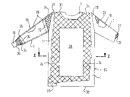
More specifically Figs. 9 and 10 show again a surgeoll's
gown comprising a body portion 20 and two arms or sleeves 10
with the left hand arm 10 (at the right side of the drawing)
being shown in part to further illustrate the internal
construction. In Fig. 9 the outer layer of the garment is
shown largely broken away at the front, again to facilitate
an understanding of the internal construction.
As can be seen ~rom Figs. 9 and 10, in particular from Fig.
10, the article of clothing or gown basically comprises an
outer layer 1 which extends all around the front of the gown
to two vertical seams 19 at the back which, in the usual
manner for surgical gowns, are tied by straps or tapes
around the back of the wearer. The same outer layer material
1 is provided for the outer layers of the sleeves including
the shoulder portions with the cross-hatching. Inside the
outer layer 1 there is provided, at the front of the
garment, an inner layer 22 which is in fact a composite
layer comprising a carrier material in the form of net
portions 24 and a foil-like membrane 26. As indicated in
Fig. 9, which is to be viewed as having been drawn with a
certain degree of artistic licence and not as a strictly
accurate technical drawing of the gown, the membrane 26 is
generally rectangular in shape and is surrounded on all four
sides by the net 24. The drawing of Fig. 9 is in fact shown
with the front layer 1 largely broken away so that the
2 ~
- 13 -
net-like carrier material or fabric 24 and the membrane 26
can readily be seen. In fact the whole of the front of the
garment is covered by the outer layer 1. At the rear the
garment only comprises the outer layer 1, here there is no
inner layer since it is not necessary at this location.
Stitched seams are indicated hy short vertical lines and the
reference numerals 21, 23 and 25.
The sleeves 10 again have the dual structure with an outer
layer 1 and an inner layer 22 with the inner layer
comprising a membrane, in this case a sleeve shape tubular
membrane 26 (typically formed by rolling a flat membrane
into a conical cylinder and forming a seam 27 at the point
where the longitudinal edges meet~, with the cylindrical
sleeve being attached to the shoulder seam 28 of the outer
sleeve material ~ with the shoulder portion 30 of the outer
layer of the gown via a net-like carrier material 24. As can
be seen from the right hand sleeve of the gown of Fig. 9
(left hand side of the drawing) the wrist end of the inner
sleeve-like membrane 26 is also connected to the cuff 16 via
a net-like material 24. That is to say the net-like insert
24 at each shoulder portion of the gown is connected ~ia a
first seam 28 to the shoulders of the body of the gown and
via a second seam 32 to the shoulder end of the sleeve
shaped inner membrane 26. The wrist end of the sleeve-like
inner membrane 26 is connected via a seam 34 to the net-like
insert 24 and the other end of this net-like insert is then
connected by a further seam 35 to the inside of the double
cuff 16, e.g. by a seam to the inside edge thereof or by
adhesi~e bonding ~o the inner side of the U-shaped space
formed by the double cuff, the mouth of the U-shaped space
beiny disposed towards the shoulder.
~t the base of the gown the inner layer 1 is turned inwardly
' ' . '
'
,'
2 ~ 3 ~i
-- 19
so that its upper edge which may be turned over on itself
lies higher than the actual lower edge 38 of the gown. In
this way a U-shaped channel is formed which can collect any
liquid which may ultimately drip downwardly from the front
membrane 26. It should be noted that this channel is not
essential and indeed it may be preferable to simply leave
the bottom edge of the gown open so that any liquid which
may penetrate the gown, or perspiration which may run from
the suryeon or wearer can simply escape downwardly onto the
floor of the operating theatre.
Various modifications are shown in the further Figs. 11 to
1~. In Fig. 11 the net-like carrier material 24 at the front
of the gown is again provided with an opening 40 (as in the
Fig. 9 and 10 embodiments) which is only fractionally
smaller than the membrane 26. In this embodiment the
membrane 26 is however removably connected to the net-like
carrier material 24 which takes place via "Velcro-type
fasteners", i.e. mating tapes 42 and 44 of material which
are sewn to the net-liXe carrier material and to the
membrane 26 respectively (or adhesively bonded thereto) and
which consist of interlocking loops and hooks in known
manner. That is to say the permanent connection effected by
stitching in the embodiment of Fig. 10, as illustrated by
the short vertical lines 21, is replaced here by a
releasable connection.
Fig. 12 shows a further similar embodiment in which the
entire inner layer comprising the net-like carrier material
24 and the membrane 26 sewn thereto is removable from the
outer layer 1, which is only shown in part for simplicity of
illustration. Again the connection takes place by means of
tapes of Velcro-like material 42, 44 sewn to the inner layer
and the outer layer 1.
2 ~
- 20 -
Fig. 13 shows another possible embodiment in which the
net-like material 24 is a continuous layer and the membrane
26 is simply sown onto this layer at the edges.
Alternatively it could be adhesively bonded to the net-like
layer 24.
In Fig. 14 the membrane comprises a composite membrane in
the form of a foil 26 which is impermeable both to liquid
and to water vapour and a backing layer 46 which is provided
on the face of the membrane 26 remote from the outer layer 1
and which can consist of an open mesh woven or non-woven
fabric. The idea of this layer is simply to provide added
comfort for the wearer and to p~ovide a certain measure of
perspiration absorption, as well as to improve the tearing
and anti-kinking properties of a (light-weight) foil
membrane. In an alternative version of this embodiment,
which is not shown in its own right the foil 26 can be a
plastic foil which is totally impervious to both liquids and
water vapour. Foils with these characteristics, and also
foils which are liquid-impermeable but vapour permeable, are
well known per se.
Finally, Fig. 15 shows an embodiment similar to that of Fig.
14 but with an additional absorbent layer 48 provided on the
face of the membrane 26 bzsing the outer layer 1 (not shown
but understood in all Figs. 13, 14 and 15 to be beneath the
layer structure illustrated). The purpose of this layer is
simple to spread any liquid which may penetrate the first
layer 1 so that it does not run off the inner membrane 26
but i.s instead retained in the absorbent material. A layer
of this kind can also be provided in all the previously
described embodiments.
2~S~
- 21 -
It will be appreciated that the net-like carrier material 24
can be formed in a variety of ways either as a true net with
meshes, or as an open mesh fabric, or indeed as a tighter
mesh fabric with a plurality of apertures formed therein. In
all cases the open structure of the fabric permits ready
flow of air therethrough and facilitates air circulation and
convection making the garment itself more comfortable for
the wearer. In addition movements of the user will produce
changes of the relative positions of the membrane and the
first layer 1 thus opening up and closing the spacing
between them, at least locally, and this will generate a
type of pump action ensuriny ready ventilation of the
garment. Moreover sterilisation and washing are improved.
,