Note: Descriptions are shown in the official language in which they were submitted.
2~8875
The present invention relate to a portable magnify-
ing reading apparatus with high convenience, which can
be effectively used by visually handicapped persons.
There have been developed magnifying reading
apparatuses for visually handicapped persons.
Conventional apparatuses are of the type whereln an out-
put from a video camera is amplified and displayed on a
TV receiver and the video camera and the TV receiver are
independent from each other. In most cases, such con-
ventional apparatuses are used in the home individually.
According to the conventional apparatus, the videocamera and the TV receiver are separate components.
Since the size of the apparatus is large, the apparatus
is not portable. In addition, it is not possible that
dlsplay characters represented by video signals produced
by a single video camera are used by two or more display
devices.
There is a demand for a convenient magnifying
reading apparatus which can be used in various modes and
various situations. For example, there is a demand for
an apparatus which can conveniently be used in a meeting,
an outdoor place, a lecture, etc. Conventlonally, a
visually handicapped person views displayed characters
with his/her face close to the screen, and it is
desirable that visually handicapped persons have their
own display devices.
An object of the invention is to provide a portable
208~875
magnifying reading apparatus with high convenience, with
which a number of persons can simultaneously view
magnified characters of a single book.
Another ob~ect of the invention is to provide a
portable magnifying reading apparatus with high con-
venience, wherein stable display and operation is
achieved.
According to this invention, there is provided a
portable magnifying reading apparatus comprising: a case
having an openable cover; a video camera removably con-
tained in the case and having a zoom function; a liquid
crystal display (LCD) device contained in the case; a
first connection terminal, provlded on a wall of the
case, for receiving a video signal from the video
camera; a second connection terminal, provided on a wall
of the case, for receiving an external video signal; and
operation means, provided in an operation unit of the
case, for selecting one of the video signal from the
video camera via the first connection termlnal and the
external video signal via the second connection ter-
minal, and supplying the selected signal to the LCD
device.
In the above apparatus, a light-weight liquid
crystal display device and a video camera are contained
in the case. Thus, the apparatus can easily carried. A
video signal is input from a similar apparatus via the
second connection terminal. Even when there is only one
2088~75
book to be scanned, many persons can view the displayed
characters with their own apparatuses, for example, in a
meeting or school.
The apparatus of this invention is provided with
means for freely varying the attitude of the LCD device.
Thereby, the degree of freedom in angle, direction and
attitude of the display is increased.
According to this invention, the case is provided
with video camera connectors at two or more locations.
Thereby, the area of movement of the video camera is
increased, and the video camera can be moved in accor-
dance with the position of an ob~ect to be scanned.
According to this invention, the LCD device can be
removed from the inside of the case. Thereby, the area
of movement of the LCD device is increased and con-
venience for the user is enhanced.
According to this invention, there is provided
means for sub;ecting an image signal output from the
video camera to binary-coding processing and inputting
the binary-coded signal to an encoder. Thereby, the
gray scale of the image signal is clearly divided to
white and black levels, and the contrast on the display
is clarified. Thus, magnified characters can be easily
recognized.
According to this invention, there is provided a
memory for storing image signal data cyclically and
keeping data fcr a predetermined time period. Thereby,
2~87~
displayed characters are not shaken even if the camera
is shaken, and stable, clear images can be obtained.
According to this invention, the video camera is
provided with a guide mechanism using a roller which
runs on an ob;ect to be scanned. Thereby, the camera
can be stably moved over the object, and stable image
pickup is achieved.
According to this invention, the video camera is
provided wlth a writing device-related mechanism.
Thereby, the user can easily add characters, marks,
underlines, etc. to the object, while viewing the moni-
tor displaying the object.
According to this invention, the video camera is
provided with illumination means having luminance auto-
matically controlled in accordance with the object.Thereby, it is possible to illuminate the object in an
optimal condition and clarify the image displayed on the
display device.
According to this invention, the video camera is
provided with illumination means capable of changing the
color of illumination light. Thereby, the color of
illumination light is selected in accordance with the
color of the object, and clear image is displayed.
This invention can be more fully understood from
the following detailed description when taken in con-
junction with the accompanying drawings, in which:
Fig. lA and Fig. lB are perspective vlews showing
2~87~
an external structure of a magnlfying reading apparatus
according to an embodlment of the present invention;
Fig. 2A and Fig. 2B are a plan view and a side view
of the embodiment;
Fig. 3 shows an example of a video camera used in
the apparatus of the embodiment;
Fig. 4 shows an example of an electric system of
the apparatus of the embodiment;
Fig. 5 shows a magnifying reading apparatus
according to another embodiment of the invention;
Figs. 6A to 6C are views for illustrating the rota-
tional operatlon of a display panel of a liquid crystal
device shown in Fig. 5;
Figs. 7A to 7D are views for illustrating the rota-
tional operation of the display panel of the liquid
crystal device shown in Fig. 5;
Fig. 8 is a magnifying reading apparatus according
to another embodiment of the învention;
Fig. 9 is a view for describing the use of the
apparatus shown in Fig. 8;
Fig. 10 is a circuit diagram showing a structure of
a signal processing circuit of the apparatus according
to the invention;
Fig. 11 is a circuit diagram showing another struc-
ture of the signal processing circuit of the apparatus
according to the invention;
Figs. 12A and 12B show another structure of the
203~87~
signal processing circuit of the apparatus according to
the invention and an example of a display image produced
by use of this processing circuit;
Figs. 13A and 13B are views for describing the
structure of a power supply system of the apparatus of
the invention;
Figs. 14A to l~C are views for describing a struc-
ture of the video camera used in the apparatus of the
invention;
Figs. 15A to 15C are views for describing another
structure of the video camera used in the apparatus of
the invention;
Figs. 16A and 16B are views for describing still
another structure of the video camera used in the
apparatus of the invention;
Fig. 17 shows an example of an automatic illumina-
tion adjusting circuit provided within the video camera
used in the apparatus of the invention;
Fig. 18 is a view for describing still another
structure of the video camera used in the apparatus of
the invention; and
Fig. l9A and Fig. l9B show still another structure
of the video camera used in the apparatus of the inven-
tion, and an electric circuit portion thereof.
Embodiments of the present invention will now be
described with reference to the accompanying drawings.
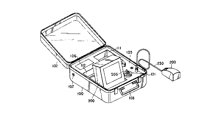
Fig. lA and Fig. lB are perspective views showing
2~88875
an external structure of a magnifying reading apparatus
according to an embodiment of the present invention.
The apparatus has a case-like external appearance. A
cover 102 is rotatably attached to one side of a case
body 100. The case body 100 can easily be carried by a
user, with the cover 102 closed and a handle 103 held by
the user. The apparatus has a plane size (i.e. two-
dimensional size) of about "B5" or "A4". Container por-
tions 111 and 112 are formed in the body 100. The
container portion 111 can receive a video camera 200,
and the container portion 112 can receive a color liquid
crystal display (LCD) device 300. The video camera 200
ls connected via a cord 230 to a connector 121 provided
on an operation panel 105 of the body 100. The video
camera 200 is taken out of the container portion 111 and
directed freely to an object in a range defined by the
length of the cord 230. The video camera 200 is pro-
vided with a zoom function and a dial for adjusting a
magnification factor.
The cord 230 may be detachably connected to the
operation panel 105 via a connector or may be fixedly
connected to the panel 105. In Fig. ls~ the cord 230 is
connected to a right portion of the body 100, but it may
be connected to a left portion thereof. In addition,
the cord 230 may be connected to one or several loca-
tions on the body 100, in consideration of convenience
for the user.
20~887~
-- 8 --
The zoom function of the video camera 200 may
employ various control methods: e.g. optical lens
control method, electronic control method based on data
read/write from/in a memory, etc. Either a video signal
supplied from the video camera 200 or an external video
signal supplied from an external connection terminal is
selected by a switch 506 formed on the operation panel
105 and the selected signal is delivered to the color
LCD device 300, as will be described later.
The color LCD device 300 can be completely con-
tained in the container portion 112, and the cover 102
of the body 100 can be closed. The display surface of
the display device 300 can be inclined and directed to
the user, as shown in Fig. lB, at the time of use. The
operation panel 105 is also provided with a dial for
adjusting the luminance of the color LCD device 300.
Fig. 2 shows a mechanism for raising and flattening
the color LCD device 300. Since the display device 300
has a flat plate shape, a one-side edge (i~e. the lower-
side edge of the display screen) is rotatably attachedto the body 100. The other-side edge is supported by
support rods 301 and 302. The support rods 301 and 302
are rotatably fixed at one end to the bottom of the
container portion 112, and are engageable at the other
end with the rear plate of the display device 300.
Accordingly, when the support rods 301 and 302 are flat-
tened and contained in the container portion 112, the
2~887S
color LCD device 300 is also rotated down into the con-
tainer portion 112. In this case, a locking mechanism
may be provided for supporting the display device 300
since the reading apparatus is designed as a portable
one.
In addition, the reading apparatus is provided with
a battery container portion 106 for portable use. The
apparatus is also provided with terminals 107 and 108
for receiving and supplying image signals from and to an
external similar apparatus(es). The use of these will
be described later.
Fig. 3 shows an example of the video camera 200.
The camera 200 has a palm-sized case and comprises a
camera 211, an optical system 212 situated in front of
the camera 211, and illumination devices 240 including,
e.g. light-emitting devices. A hole 215 is formed in
the lower part of the case, so as to correspond to the
optical system 212. A zoom switch 216 is provided on
the upper part of the case.
The video camera 200 is used such that it is
scanned over lines of a page of a book to be read. A
location corresponding to the hole 215 is illuminated,
and an image in the hole 215 is input to the camera 211
via the optical system 212. The camera 211 delivers a
video signal to a video processing circuit in the camera
case 201 via a cord, and the video signal ls processed
in the video processing circuit. The processed video
2~8887~
-- 10 --
signal is displayed on the color LCD device 300. The
user can view enlarged characters scanned by the camera
211 and displayed on the display device 300.
various types of video cameras 200 may be used.
The video camera 200 may be provided with a dial for
adjusting the intensity of illumination. In addition,
the video camera 200 may be provided with adjusting
dials which are normally provided on the color LCD
device 300, so that all operations may be controlled by
one hand. Furthermore, regarding the relationship bet-
ween the video camera 200 and the signal processing
device, it is possible to provide memory means for
storing, e.g. characters of several lines. Thereby, the
user's scanning operation is simplified, and the user
need not successively move the camera body in units of
one to five characters.
The electric operation of the above apparatus will
now be described.
In Fig. 4, numeral 401 denotes a zoom lens. An
optical image enlarged by the zoom lens 401 is focused
on an image focusing surface of a CCD solid pickup ele-
ment 402. An image signal output from the pickup ele-
ment 402 is converted to a video signal in a video
signal processor 501. An output signal from the video
signal processor 501 is delivered to an external output
terminal 504 via an output amplifier 503 and simulta-
neously to one of the terminals of a switch 506 via
2~875
-- 11
an amplifier 505. The switch 506 selects either an
external input signal from an external input terminal
511 or an output signal from the amplifier 505. The
selected signal is supplied to a color addition pro-
cessing circuit 507. In the circuit 507, for example,
a single-color signal (e.g. red, yellow) is added to a
character signal included in the video si~nal. The
video signal including the color signal is output from
the color addition processing circuit 507 to the color
LCD device 300 via an output amplifier 509, and the
video signal is displayed such that only characters, for
example, are colored.
According to this apparatus system, when the switch
506 selects the signal from the external input terminal
511, an external output video signal is input to the
system from another similar portable liquid crystal
magnifying reading apparatus and the contents of a text
read by another person can be displayed on the color LCD
device 300. Further, the video signal input from the
2~ external input terminal 511 can be delivered via an
external output terminal 512 to another similar reading
apparatus as external input video signal. Thus, while a
person is reading a book with the aid of the magnifying
reading apparatus, other persons can read the same book
with similar reading apparatuses via the external input
terminal 511 and output terminal 512.
The color signal to be added to the character
2Q~87~
signal in the color addition processing circuit 507 can
be changed by a switch 508. The color, which can per-
ceived by the user most easily, is selected. The switch
508 may be freely operated by the user, or may be preset
by the manufacturer when the user is known beforehand.
A color to be easily recognized by a visually han-
dicapped person is, in some cases, limited and, in this
case, that color is added to characters. A color signal
is added to a character signal, for example, in the
following manner. Suppose that a book is now being
scanned. A monochromatic luminance signal having a pre-
determined level or above (or below) may be determined
to be a character signal. Accordingly, the luminance
signal is input to a slicing circuit, and a signal
(character signal) having a predetermined level or above
is derived. A carrier color signal is superimposed on
the luminance signal with a timing corresponding to
character signals, thereby enabling the display device
to display colored characters. The derived character
signal is used as a switch control signal, and the
carrier color signal is superimposed on the luminance
signal via the switch.
A power source system of the above-described
apparatus will now be described. A commercial electric
power supplied from a plug 521 is rectified and smoothed
by a power supply circuit 522. The smoothed power is
supplied to th0 respective circuits through a switch
2~887S
523, a fuse 524 and a power supply switch 525. Since
the reading apparatus is portable, a battery 526 may be
mounted for convenient use. When the battery 526 is
used, the switch 523 is connected to the battery side.
A resistor 514 connected to a switch 513 is used for
matching, when the external output is not required.
The above-described reading apparatus has various
features. The battery 526 can be used since the reading
apparatus is portable. The color LCD device 300 is used
for reducing the weight of the apparatus. Since color
display is achieved, characters can be displayed with
color which can be most easily recognized by a visually
handicapped person. Further, two or more magnifying
reading apparatuses can be connected to the present
apparatus, so that one book can be read by many persons
simultaneously. For example, when there is a teacher
and many students, signals can be supplied from the
teacher's reading apparatus to the students' apparatu-
ses. In a meeting, too, a document owned by a leader
can be transmitted to many persons via the external out-
put terminal.
In addition, this reading apparatus system is
applicable to various uses. For example, a document is
placed on the cover 102 shown in Fig. lB and scanned by
the video camera 200, a clipping mechanism may be pro-
vided to fix the document, or a guide mechanism for the
video camera 200 may be provided.
2~887~
- 14 -
As has been described above, the present invention
can provide a convenient magnifying reading apparatus
wlth which a book can be simultaneously read by many
persons.
Fig. 5 shows another embodiment of the invention,
wherein a supporting mechanism for supporting the color
LCD device 300 differs from that of the preceding embo-
diment. The supporting mechanism will now be described
in detail.
The color LCD device 300 can be completely con-
tained in the container portion 112 and the cover of the
case body can be closed. When the color LCD device 300
is used, the display screen can be directed to the user,
for example, by means of a hinge mechanism, as shown in
Fig. 5. The operation panel 105 is provided with a dial
for adjusting the luminance of the color LCD device 300.
The color LCD device 300 comprises a rectangular
display panel 301, a panel holder 302 for holding the
display panel 301, and engaging means for engaging the
display panel 301 with the panel holder 302 such that
the display panel 301 is movable on the holder 302 in
both longitudinal and transverse directions. The
display face of the display panel 301 has an aspect
ratio of, e.g. 3 : 4. In the normal horizontal posi-
tion, the display face is suitable for disp]aying hori-
zontally arranged characters. The display face,
however, can be rotated 90 in the vertical position so
208887~
- 15 -
that it can effectively display vertically arranged
characters.
Figs. 6 and 7 are views for illustrating the mecha-
nism for changing the attitude of the display panel 301
of the color LCD device 300. Figs. 6A to 6C show the
process of ~hanging the attitude of the display panel
301, as viewed from the front side. Figs. 7A to 7D show
the process of changing the attitude of the display
panel 301, as viewed from the rear side. The attitude
of Flg. 6A is suitable for reading of horizontally
arranged characters. To change the attitude of Fig. 6A
to one suitable for reading of vertically arranged
characters, the display panel 301 is slid upward
(Figs. 6A and 7B), rotated 90 (Figs. 6B and 7C), and
moved downward (Figs. 6C and 7D). The vertical attitude
is restored to the original horizontal attitude by the
steps of reverse order. The panel holder 302 is pro-
vided with a slit 303 in which pins 304 and 305 of the
display panel 301 are inserted.
When horizontally arranged characters are scanned,
the longitudinal axis of the image pickup face of the
camera is situated horizontal. When vertically arranged
characters are scanned, the longitudinal axis of the
lmage pickup face of the camera is situated vertical.
Thereby, an effective image with a maximum number of
characters can be obtained.
The structure of the video camera 200 shown in
2~887~
- 16 -
Fig. 5, which differs from that of the video camera 200
shown in Figs. 1 and 2, will be described later.
In the above embodiment, the color LCD device 300
is arranged within the case body 100. However, lf the
color LCD device 300 can be situated apart from the case
body 100, the convenience for the user increases.
Fig. 8 shows still another embodiment. In this
embodiment, corner portions of the upper face of the
case body 100 are provided with connectors 121, 122, 123
and 124 for connection with the video camera. The color
LCD device 300 can be removed from the container portion
112 and located at a position apart from the case body
100 by a distance corresponding to the length of a cable
299. With this structure, as shown in Fig. 9, a loca-
tlon area 200A of the video camera 200 and a location
area 300A of the color LCD device 300 are enlarged. The
user can freely decide the location for use of the video
camera 200 and color LCD device 300, and the convenience
for the user is enhanced. In this embodiment, both
location areas of the color LCD device 300 and video
camera 200 are eniarged, but only one o~ the location
areas may be enlarged.
Fig. 10 shows a characteristic portion of the
above-described electric signal processing system.
In a system using a regular solid image pickup
device, a monochromatic image of 8 gray scales is input
and a magnified image is output to a display device.
208887~
- 17 -
However, in the above-described magnifying reading
apparatus, in some cases, the solid image pickup device
cannot obtain clear black character images of 8 gray
scales because of insufficient luminance of characters
or color characters, and a visually handicapped person
has difficulty in reading. In addition, depending on
the intensity of illumination, clear black character
images may not be obtained. Further, owing to roughness
on the page of a book, correct focusing of the image
pickup device cannot be achieved, and clear black
character images cannot be obtained.
Under the circumstances, according to the present
apparatus system, in the image input unit, clear
contrast (light~dark) is obtained and character image
signals are converted to binary signals for easy
reading. The image input unit comprises a solid image
pickup device, means for comparing an image pickup
signal obtained by the solid image pickup device with a
predetermined reference level, thereby obtaining a
binary image pickup signal, and an encoder for encoding
the binary image pickup signal obtained by this means
and producing a video signal. Since the image pickup
signal is obtalned as a binary t"black" or "white")
signal, the displayed character images have a very clear
contrast and are easy to read.
Referring to Fig. 10, an image pickup signal
obtained by a solid pickup element 402 is amplified by
2~8~75
- 18 -
an amplifier 531 and input to a binary-coding circuit
532. The binary-coding circuit 532 includes a com-
parator circuit 534 for comparing an input image pickup
signal with a reference voltage 533 and producing a
5 positive signal (+)S and a negative signal (-)S. A
switch 535 selects either the positive signal or nega-
tive signal and supplies it to an NTSC encoder 536. The
encoded video signal is delivered to the external output
terminal 504 via the output amplifier 503 and supplied
to the LCD device 505.
When the switch 535 selects the positlve signal
(+)S, a white-level signal component of the image pickup
signal obtained by the solid pickup element 402, which
has a sufficient luminance, is derived. Thus, when a
15 book, etc. is scanned, a magnified image with clear
contrast (character = black; background = white) can be
viewed. Even when color characters (e.g. green or red)
appear on the book, white and black (= character) images
are displayed since the image pickup signals are sub-
jected to binary coding processing. In addition, whencorrect focusing of the pickup element is not achieved
owing to roughness on the page of the book, unclear ima-
ges are formed in the prior art. However, according to
the invention, clear black-level character images are
obtained. If the switch 535 is changed over to the
signal (-)S side, white character images and black
background images are obtained.
2a8~87~
-- 19 --
In the above embodiment, the monochromatic display
is used. However, a color display may be used. In this
case, a color generator is provided at an output unit of
the encoder, and when a black-level signal, for example,
is input, a color signal (red or green) is produced.
Fig. ll further shows the characteristic portion of
the electric signal processing system.
When a magnifying reading apparatus is used, the
user holds a small-sized camera using a solid pickup
element (CCD element) by one hand, and slides it over
lines of a book, etc., and a magnified image is
displayed on a display unit. Since the camera is slid
over the sheet surface of the book, etc., the camera is
slightly shaken. As a result, a magnified image is
greatly shaken and the user has dlfficulty in reading.
According to this embodiment, the displayed image
is temporarily made static, for easier reading of
magnified characters. For this purposed, the apparatus
comprises a solid pickup element for converting an opti-
cal image of an ob~ect to an electric signal, storingmeans for storing an image pickup signal corresponding
to one field of the solid pickup element, read-out means
for repetitively reading out the signal stored in the
storing means, and switching means for changing the
cycle of the storing operation of the storing means by
remote control. Thereby, the static display time for
statically displaying the magnified image is set by the
2~887~
- 20 -
changed cycle of the storing operation of the storing
means. In accordance with the reading speed, the static
display time can be set. In the static display state,
the screen is not shaken irrespective of shaking of the
camera, and the user can easily read the displayed
characters.
In Fig. 11, an optical image of the object is
focused on the pickup face of the solid pickup element
402 via the optical system 401. The solid pickup ele-
ment 402 receives a drive pulse from a drive pulsegenerating circuit 542 to read out the photoelectrically
converted charge by vertical cycle field shift, horizon-
tal cycle horizontal transfer. The optical image is
output from the solid pickup element 402 as a pho-
toelectrically converted image signal and then amplifiedby the amplifier 531. Th0 amplified signal is input to
the signal processing circuit 532. The signal pro-
cessing circuit 532 is, for example, a binary coding
circuit. The amplified signal is subjected to binary
coding processing, and the processed signal is output to
a field (or memory) memory 541. The storing time of the
memory 541 is controlled ~y a refresh timing pulse from
a static display time setting circuit 543 (described
later). A signal corresponding to, e.g., one field is
repetitively read out from the memory 541 at a field
cycle and delivered to the NTSC encoder 536. The
encoded NTSC signal produced by the NTSC encoder 536 is
208~87~
- - 21 -
output to the output terminal 504 via the output
amplifier 503.
The static display time setting circuit 543 can set
the write operation timing of the memory 541 to, e.g.
one per 5 seconds, one per 10 seconds, one per 15
seconds, or one per 20 seconds. On the other hand, the
solid pickup element 402 performs the image pickup
operation at the cycle of 1/60 second. The refresh
cycle of the memory 541 can be changed by the user by
operating a refresh cycle changing unit 544.
Accordingly, the user can set the speed of so-
called "still image feeding" in accordance with the
user's reading speed. While the static image is
displayed, displayed characters are not shaken even when
the camera is shaken.
In the above embodiment, the memory 541 is provided
midway in the image signal line, and the storing time of
the memory 541 is set. However, it is possible to con-
nect a charge storing portion to the solid pickup ele-
ment 402 and set the storing time of the charge storingportion. In this case, however, it is necessary to pro-
vide the storing portion with a signal charge return
loop.
In the above embodiment, the signal charge
corresponding to one field is read out from the solid
pickup element 402 at a normal cycle of 1/60 second.
However, the solid pickup element may be provided with
2~875
- 22 -
a so-called shutter function. Speclfically, when an
image of a fast-moving ob~ect is picked up, the shutter
function is performed to select 1/500 second, 1/1000
second, etc., and the read-out signal is stored in the
memory 541 for repetitive display.
Fig. 12 shows still another embodiment of the
invention. By providing the memory 541, as shown in
Fig. 11, a multi-screen can be obtained. For example, a
picture portion on a page of a book is stored in the
memory 541 and displayed on a half screen, while charac-
ters are displayed on the other half screen (see
Fig. 12B). For this purpose, as shown in Fig. 12A, data
on the picture portion is stored in the memory 541 as
static image data, and thereafter normal scanning is
performed. A half screen static mode is designated by
a mode changing unit 544. Thereby, an output from the
memory 541 and an output from the signal processing cir-
cuit 532 are alternately selected by a switch 545 for
every half-screen period. Specifically, these two out-
puts are alternately changed at every 1/2 horizontalcycle. By this function, the user can read characters
while viewing the picture on the screen.
Fig. 13A shows an embodiment of a power supply
system used in a magnifying reading apparatus. Since
the magnifying reading apparatus is portable, it is
required that a commercial power supply be available, an
adaptor be available since commercial power voltage
208~875
- 23 -
varies according to area, and a battery be available
when commercial power supply cannot be used. Since two
or more supply sources are available, a power source
selecting function is required.
In Flg. 13A, a plug 131 is connected to a commer-
cial power supply. The plu~ 131 is connected via a cord
to an internal AC/DC converter 132 provided within the
apparatus body 100. An output from the internal AC/DC
converter 132 is a DC voltage suitable for internal cir-
cuits of the magnifying reading apparatus and the output
is supplied to one input terminal of a switch 133. A
plug 134 is provided on an external AC/DC converter 135.
An output from the external AC/DC converter 135 is
supplied to a connector 136. The connector 136 can be
coupled to a connector 137 provided on the apparatus
body 100. An output from the connector 137 is supplied
to the other input terminal of the switch 133.
The switch 133 is designed to select the output
from the connector 137 by a mechanical change-over
member, when the connector 136 is connected to the con-
nector 137. When the connectors 136 and 137 are not
used, the switch 133 is designed to automatically select
the output from the internal AC/DC converter 132.
An output from the switch 133 is supplled to a power
source selector and one of the input terminals of a
switch 139. The input terminal of the switch 139 is
supplied with an output of a battery 140 mounted in the
2~875
- 24 -
apparatus body 100.
The switch 139 is designed to automatically select
the output of the battery 140 in the normal state.
However, when the power source selector 138 responds to
the output voltage from the switch 133, the switch 139
is operated to select the output of the switch 133 by an
output control signal of the power selector 138. In
other words, the power from the plug 131 or 134 is pre-
ferentially used. The output from the switch 139 is
supplied to a distribution network 141 and supplied to
internal circuits as power supply voltage.
Fig. 13B shows an embodiment wherein there is pro-
vided a voltage detector 142 for monitoring voltage of
the battery 140. The output from the battery 140 is
supplied to the switch 139 via a transistor Q2. The
output of the battery 130 is supplied to the voltage
detector 142. The output voltage of the battery 140
decreases to a predetermined value or below, the voltage
detector 142 turns a transistor Ql off. When the tran-
sistor Ql is turned off, the transistor Q2 is also
turned off.
Fig. 14 shows an example of the video camera 200.
The video camera 200 is used in contact with a book
and scans characters on pages of the book. When the
user moves the video camera 200 along lines of charac-
ters, however, the movement of the camera 200 is not
stable. If the user fails to pay attention to the
2 ~ 7 S
camera 200, the course of movement of the camera 200 may
be diverted. Since the characters are magnified on the
display, the diversion of the course of the camera 200
results ln considerable shaking of characters on the
screen.
According to this system, when the video camera is
moved along lines of characters on a page with its tip
portion in contact with the page, the course of movement
of the camera is stabilized and the operability is
enhanced.
For this purpose, a columnar rubber roller is rota-
tably provided at a pickup-side edge portion of the
camera case. The camera case holds an image pickup
camera and a magnifying lens situated in an optical path
of the camera. The axis of the rubber roller is perpen-
dicular to the direction in which the roller is moved.
~y this structure, stable movement means for the
video camera is obtained. Since the rubber roller has a
directivity with respect to the surface of the page, the
movement of the video camera is stabilized and charac-
ters are easily read.
In Fig. 14, the video camera 200 comprises a camera
211 in a small-sized camera case 201, an optical system
212 constituted by a magnifying lens situated in front
of the camera 211, and illumination devices 240. A
lower part of the case is provided with an axially
extending hood 213. The hood 213 is part of the case
2~8875
and situated at the optical system 212. The hood 213
has a flared shape, and a side portion thereof is pro-
vided with an opening 214 through which writing means
such as a pencil is inserted. Thus, it is possible to
display the state in which characters are written by the
user with wrlting means. A zoom switch (not shown) is
provided on an upper part of the case.
At the tip portion of the hood 213 ( i . e. tip por-
tion of the case), a notch 220 is formed to face the
opening 214. A rubber roller 223 is rotatably provided
between bent-up portions 221 and 222 formed at the notch
220. The axis of the rubber roller 223 is perpendicular
to the direction in which the camera is moved. When the
tip portion of the video camera 200 is placed on the
lS surface of the page, the rubber roller 223 is also put
in contact with the surface of the page. Accordingly,
when the video camera 200 is slid in a direction of the
arrow, the direction of sliding movement is determined
by the rotational movement of the rubber roller 223.
Thus, the camera is not shaken laterally and is stably
moved along lines of characters. In addition, sliding
members 224 and 225 with less frictional resistance are
provided at both ends in the direction perpendicular to
the direction of movement of the camera.
When the video camera 200 is used for reading, it
îs slid over lines on a page of a desired book. Then, a
location below the hood 213 is illuminated, and an image
2 ~ 5
of the illuminated location is picked up by the optical
system 212 and delivered to the camera 211. An image
pickup video signal from the camera 211 is processed by
the video processing circuit built in the case body 100
and the processed signal is displayed on the color LCD
device 300. The user can vlew the magnified characters
scanned by the camera 211 on the color LCD device 300.
Further, when additional lines or characters are written
between the lines on a page by the user, the writing
means such as a pencil is inserted from the opening 214
and the user can view the state in which such lines or
characters are written. The hood 213 is rotatable rela-
tive to the camera case 201, and the direction of inser-
tion of the writing means is freely set when it becomes
necessary to change the attitudes of the display panel
("vertical" or ''horlzontal'') and the camera. In addi-
tion, the camera is easily handled by either a right-
handed person or a left-handed person.
Various modifications may be made to the video
camera 200. The video camera 200 may be provided with a
dial for adjusting the intensity of illumination or a
dial for adjustment (in luminance or color) of the color
LCD device 300. In this case, all operations can be
made by one hand. Furthermore, .egarding the rela-
tionship between the video camera 200 and the signal
processing device, it is possible to provide memory
means for storing, e.g. characters of several lines.
2~875
- 28 -
Thereby, the user's scanning operation is simplified,
and the user need not successively move the camera body
in units of one to five characters.
Fig. 15 shows another embodiment of the video
camera. The video camera 200 is provlded with stable
movement means, as described above. In this embodiment,
however, even if the direction of movement of the video
camera 200 is changed 90, stable movement is ensured.
In Fig. 15, the parts common to those in Fig. 14 are
denoted by like reference numerals.
The video camera 200 comprises a camera 211 in a
small-sized camera case 201, an optical system 212
constituted by a magnif~ing lens situated in front of
the camera 211, and illumination devices 240. A lower
part of the case is provided with an axially extending
hood 213. The hood 213 is part of the case and situated
at the optical system 212. The hood 213 has a flared
shape, and a side portion thereof is provided with an
opening 214 (not shown) through which writing means such
as a pencil is inserted. Thus, it is posslble to
display the state in which characters are written by the
user with writing means. A fixed ring 251 is attached
by screws 2~2 to the inner peripheral surface of the tip
portion of the hood 213 ( i . e. tip portion of the case).
A rotatable ring 253 is provided under the fixed ring
251. An annular groove 254 (see Fig. 15B) is formed on
that part of the outer periphery of the rotatable ring
2~875
- 29 -
253, which corresponds to the screws 252. Tip portions
of the screws 252 are engaged in the annular groove 254.
Thereby, the rotatable ring 253 is rotatable relative to
the fixed ring 251, but is made axially immovable by the
engagement between the screws 252 and groove 254.
Recesses 25a, 25b, 25c and 25d, which constitute a
click mechanism, are formed in the upper surface of the
rotatable ring 253, for example, at angular intervals of
90. On the other hand, balls 26 and 27 are arranged on
that surface of the fixed ring 251 which is opposed to
the rotatable ring 253, for example, at angular inter-
vals of 1~0. The balls 26 and 27 are situated in
through-holes extending in the thickness direction
(axial direction) of the fixed ring 251, and the balls
26 and 27 are urged downwards by springs 26a and 27a.
Thus, when the fixed ring 251 and rotatable ring 253 are
assembled, the balls 26 and 27 are engaged in the
recesses 25a and 25c or the recesses 25b and 25d,
thereby positioning the rotatable ring 253.
For example, two rollers 261 and 262 are attached
on the lower surface o~ the rotatable ring 253 in
parallel to each other. The rollers 261 and 262 have
columnar shapes and are rotatable. When the video
camera 200 is slid in a direction perpendicular to the
axes of the rollers 261 and 262, the rollers 261 and 262
rotate and determine the direction of movement of the
video camera 200. The direction of rotation of the
2~8g87~
- ~o -
rollers 261 and 262 can be made to coincide with the
horizontal direction of the image pickup face of the
camera 211, as shown in the upper part of Fig. 15C, or
can be made to coincide with the vertical direction of
the image pickup face. This is achieved by rotating the
rotatable ring 253. For example, when the video camera
200 is moved in the horizontal direction to magnify and
read the surface of a document, the direction of the
rollers 261 and 262 is set, as shown in the upper part
of Fig. 15C. When the video camera 200 is moved in the
vertical direction, the direction of the rollers 251 and
262 is set, as shown in the lower part of Fig. lSC.
Thereby, the operability of the video camera 200 is
enhanced.
Referring to Fig. 14, another function of the video
camera 200 will now be described. The user may add
underlines or memorandum to a book, while reading the
book.
According to this system, memorandum, addition or
correction can be made between lines of a page of a book
while the magnified characters scanned by the video
camera 200 are displayed on the display device.
For this purpose, the flare-shaped hood is attached
to an image-pickup side part of the case which holds the
camera and the magnifying lens situated in the optical
path of the camera. A side portion of the hood is pro-
vided with the opening 214 through which the writing
2~8~7~
means can be easily inserted. Thereby, the writing
means can be inserted through the opening and characters
can be written on the page on which the hood is placed.
An image showing the state in which characters are being
5 written can be magnified and viewed. Needless to say,
the video camera shown in Fig. 15 may be provided with
the opening 214.
Fig. 16 shows another embodiment of the invention
wherein the video camera 200 is associated with writing
means. This embodiment is effective when writing must
be made in a small area. The parts common to those in
the preceding embodiments are denoted by like reference
numerals, only different parts are described. In this
embodiment, a fixed ring 255 is attached by screws (not
15 shown) to the inner periphery of the lower end portion
of the hood 213. Balls 256 are provided at some loca-
tions on the lower surface of the fixed ring 255,
thereby making the movement of the video camera 200
easier. Further, a writing means holder 257 is provided
20 on the upper surface of the fixed ring 255. When
writing means 258 is attached to the holder 257, a tip
portion of the writing means 258 is located at the
center of the image pickup area.
By using the video camera 200, the user can write
characters, etc. while viewing the magnified display on
the display device. In this case, the video camera 200
needs to be freely movable in all directions. Thus, the
2~875
- 32 -
balls 256 are rotatably attached on the lower surface of
the fixed ring 255.
Fig. 17 illustrates the relationshlp between the
video camera 200 and the illumination means thereof.
When the magnifying reading apparatus is used,
there may be a case where a dark area and a light area
are mixed, depending on the situation for use. In such
a case, unless the intensity of illumination is stabi-
lized, the user has difficulty in reading.
According to this system, the light emission amount
of the light-emitting element is automatically adjusted
in accordance with the ambient darkness. Thus, stable
images can be obtained without using illumination equip-
ment. The means for this comprises a solid pickup ele-
ment, level detection means for detecting the level of
an image signal obtained from the solid pickup element,
comparing means for comparing the detected level and a
reference level and obtaining a difference output, and a
light-emission element, situated on the side of the
solid pickup element, for emitting light to the image
pickup area. The intensity of emitted light is
controlled by the difference output from the comparing
means.
By the above means, an object to be scanned is
always illuminated with light of a preset level. Thus,
the monitor can display a clear image.
Referring to Fig. 17, an image signal obtained from
2~875
the solid pickup element 402 is amplified by the
amplifier 531. The amplified signal is supplied to the
signal processing circuit (shown in Figs. 10 and 11) for
performing signal processing for displaying images on
S the monitor. The output from the amplifier 531 is also
supplied to a level detection circuit 601 for detecting
the level of the image signal. The detected level is
supplied to one input terminal of a comparator 602. A
reference level produced by a level setting circuit 603
is supplied to the other input terminal of the com-
parator 602. The comparator 602 can produce a dif-
ference output corresponding to the difference between
the input detected level and the reference level. The
difference output from ti~e comparator 602 is used as a
control signal for a current control transistor 604.
When an average level is lower than the reference level,
the control current increases to cause more current to
flow through the transistor 604. The output current of
the transistor 604 is supplied to the light-emitting
element functioning as illumination device 240, and it
controls the intensity of light emitted by the light-
emitting element. Thus, the light-emitting element
(illumination device 240) can emit light of the
reference level. The reference level can be varied by
adjusting an adiuster 605.
In Fig. 17, one illumination device 240 is repre-
sentatively shown, but a plurality of light-emitting
2 ~ 7 5
- 34 -
elements are actually arranged near the edge of the
solid pickup element 402, thereby uniformly illuminate
the ob;ect.
Fig. 18 shows an example of the structure of the
video camera including the circuit shown in Fig. 17.
Numeral 201 denotes a cylindrical case with a bottom.
The camera case 201 has such a size that it can be held
by one hand. Within the camera case 201, a lens system
212 is arranged on the opening side and a solid pickup
element 402 is arranged on the bottom side. An optical
image coming from the lens system 212 is focused on a
focusing face of the soLid pickup element 402. An image
signal output from the solid pickup element 402 is
supplied to a control unit via a signal line of a cord
230 attached to a side portion of the camera case 201.
A plurality of illumination devices constituted by
light-emitting elements Dl, D2... are arranged near the
tip portion of the lens system 212. The illumination
devices are driven by the circuit shown in Fig. 17. The
opening portion of the camera case 201 is provided with
a hood 213. The hood may be replaced with leg-shaped
spacers. A roller 261 is rotatably attached at the tip
of the hood 213 for smooth movement on the book. When
the camera body is moved, the direction of the movement
is determined by the roller 261, and lateral shaking is
prevented. A sliding member 263 including a roller is
provided at a location opposed to the roller 261.
2~3~87~
According to the above image input means, the sur-
face of the object to be scanned is kept at a reference-
level brightness. Thus, there is no need to provide an
external illumination adjusting means, and the handling
of the camera is very easy.
In the above description of the embodiment, the
characteristic of the light-emitting device has not been
mentioned. However, various colors of light, e.g.
white, red, blue, and green, may be chosen, and illumi-
nation color may be switched. The solid pickup element
402 may be a monochromatic or color device. There are
persons who are not sensitive to red or who are excessi-
vely sensitive to red. In this case, the emission light
color may be switched to one which is clearly recognized
on the monitor by the user.
AS has been described above, according to the pre-
sent apparatus system, the size of the illumination
device is small and the illumination intensity is auto-
matically adjusted.
Fig. l9A shows still another embodiment of the
video camera 200. The structure of the camera shown in
Fig. l9A is identical to that of the camera shown in
Fig. 18, and the detailed description thereof is
omitted. In this video camera 200, various kinds of
emission colors can be switched. Fig. 19A is a lower-
side view of the video camera. In this embodiment, for
example, two colors can be selected. Red-light emission
2o~887~
- 36 -
elements Drl, Dr2 and Dr3 are equidistantly arranged
around the camera using a solid pickup element, and also
blue-light emission elements Dbl, Db2 and Db3 are
e~uidistantly arranged. Though not shown, colorless
light emission elements Dl, D2 and D3 are also arranged
equidistantly.
Fig. l9B shows a switching circuit for the light
emission elements. Switches 611, 612 and 613 are
arranged in parallel to a power supply line. The light
emission elements Drl to Dr3 are connected in parallel
between an output terminal of the swltch 611 and a
ground line. The light emission elements Dbl to Db3 are
connected in parallel between an output terminal of the
switch 612 and the ground line. Further, the light
emission elements Dl to V3 are connected in parallel
between an output termlnal of the switch 613 and the
ground line. The switches 611, 612 and 613 are exposed
on the outer periphery of the camera case 201 and can be
operated by the hand.
By switching the emlssion light color, the color of
the ob;ect is made different from the color of illumina-
tion light, thereby obtaining clear display images. In
the above embodiment, the illumination light color can
be switched, but it is possible to use changeable film
filters with transparent illumination light being
employed.