Note: Descriptions are shown in the official language in which they were submitted.
CA 02088993 2001-12-17
WO 92/02996 ~ . PCT/SE91/00526
l ._
1
MODULAR RADIO COMMUNICATION SYSTEM
Wide area radio network systems of cellular type is a
well-known and tried way of solving communication problems.
An example of such a system used in mobile applications is
NMT (Nordic Mobile Telephone system) and GSM (Global System
for Mobile communications). For fixed applications SR100
(Subscriber Radio) and SR500 from the Canadian Company (SR
Telecom) can be mentioned.
In the systems mentioned above frequencies in adja-
cent or overlapping service areas that are served by the
systems are used to prevent interferences between stations
from occuring. This means that it is not possible to
achieve redundancy in the system on common frequency bands
in the different service areas which otherwise would be the
most frequency efficient and economic solution. There are
also problems in expanding said systems with reference to
capacity and area covering without a deteriosation of the
frequency efficiency.
Radio network systems comprise one or several central
stations (CS) and a plurality of peripheral stations (PS)
connected thereto. If a high security and an efficient
redundancy, or recoupling ability between different (CS)
operating within the same or any adjacent service area,
should be obtainable within the framework of previously
known technique said stations must be capable of operatiil'g:- .."
on different frequencies so as to avoid interference. This
leads to unnecessarily complicated and expensive stations.
The construction and function of a CS in existing systems
with respect to control functions is very fixed and no
flexibility is allowed.
An object of the present invention is to overcome the
problems mentioned above and to provide a radio network
system also allowing interaction between different CS and
PS and between control function units of said stations with
respect to actual needs.
CA 02088993 2001-12-17
WO 92/02996 PCT/SE91/00526
~._.
2
According to the invention there is provided, among
other things, efficient redundant radio solutions, a
flexible increase of capacity in modular steps, a modular
economically flexible construction, and cooperation with
wide band transport networks, or integration with logical
telecommunication networks in different hierarchical or
decentralized radio networks configurations. Thereby
several new and essential properties are provided compared
to the existing technique.
The method is implemented by combining several system
componements, and radio systems and functions that are
constructed similar in character into subsystems. The
central stations of said subsystems are provided with a
transmission interface accomplishing a physical dividing of
said stations into at least two main function units, a so
called high frequency and a so called low frequency. The
subsystems are provided with units which are similar in
character, and with functions, i.a. for coordinating
traffic simultaneously in the same or adjacent service
areas) on the same frequency band in time duplex or
frequency~duplex, or adjacent or alternative frequency
bands which can be established in dependancy of a varying
capacity demand or function to accomplish a modular
capacity variation, an efficient redundancy and a flexible
traffic coupling, and also a modular construction of z~
varying service areas through interaction with~other
telecommunication networks, for instance wide band fibre
solutions.
The subsystems are provided with centrally located
central stations (CS), each of which covering a certain
service area within for instance a cell sector, and
according to which the physical construction of each CS
provides a possibility to interact with other CS to '
accomplish, i.a., the new characteristics mentioned above.
WO 92/02996 PCT/SE91/00526
2088993
Within each subsystem information is transferred for
an internal signalling and also user traffic for one or a
- plurality of connected and geographically spread out
peripheral stations (PS) within each service area. Said
PS's are preferrably constructed with units and a structure
similar to the one used in said CS's if this is desired. A
result thereof could be a number of advantages with respect
to the implementation thereof.
In each of said subsystems connected customers share
one or several common radio channels or transmissions
resources. Fixedly set up or dynamically allocated channels
are established for different needs of traffic capacity.
Thereby several PS's under each of the CS's commonly can
share one radio channel on one frequency band or one pair
of frequencies. Varying flows of capacity can be allocated
to different customers as parts of the total channel
capacity in each of said subsystems.
The method and the implementation thereof in a system
for a wide area radio will provide improvements over prior
art technique within i.a. the following areas, to give a
summary:
a modular expansion in different service areas and a
modular variation of capacity through in interaction with
other telecommunication connections as a transporting
network,
equipment diversity and space diversity,
a high and possible modular variation of the frequen-
cy efficiency,
a flexibility at traffic stops by rearranging for
different parts of a system,
a modular and physically simple structure,
new possibilities for coupling and traffic redundan-
cy.
The method described in the present application as
well as the generic method described in PCT/SE89/00470 and
WO 92/02996 PCT/SE91/00526
._
~ t~~
4
PCT/SE90/00681 can be used in terrestrial wide area radio
systems or can be implemented in satellite systems. Parts
of a CS, i.e. the radio antenna and control units, are
mounted in the satellite. Communication can be established
between the CS's and also between a CS and a PS.
Prior art technique in the technical field of wide
area radio is characterized for instance by TDMA (Time
Division Multiple Access) for sharing resources of radio
channels, for instance in fixed applications by allowing
only one frequency band to be utilized for one central
station at the time. To obtain redundancy, for instance 1+1
solutions, that is one permanent and one standby-radio
channel, which should be allowed to operate simultaneously,
an allocation of parallel frequencies is required.
FIG. 1 shows the basic construction of a wide area
radio system in fixed applications. Said figure shows
schematically an example of the problem of obtaining
redundancy, diversity. When only redundancy with respect to
the equipment is desired the systems are provided with for
instance a parallel radio unit functioning at the same
frequency band as the operating system. If the operating
radio unit gets out of order it is possible to switch on
the other unit.
The problem shows that frequencies should be ex-
changed to obtain a full redundancy or a parallel operation
of several systems. The example described above also shows
the difficulties of obtaining a high frequency efficiency
with conventional wide area systems. In cases where fre-
quency efficiency is desired isolation is required which
can be achieved by distances between different cells
functioning on the same frequency band, if they should
operate simultaneously. If such systems are delimited to
smaller cells or a smaller covered area the frequency
efficiency is increased and a given frequency can be
repeated more frequently within an area. This technique is
CA 02088993 2001-O1-22
utilized mainly within mobile communication. If for
instance a communication solution is desired outside houses
and buildings this would lead to drawbacks such as a short
range of operation, and many base stations are required. No
~i methods or systems are developed for wide area radio
systems providing an interaction and coordination and
cooupling of traffic between alternative CS's of similar
structure at the same "sites", each of which covering an
adjacent cell or the same cell or sectors or space, and
also geographically spread out peripheral stations (PS)
connected thereto and signals connected to said peripheral
stations between each other for conventional wide area
systems or systems according to the international applica-
tions mentioned above utilizing a time and space multiple-
1!i xing to achieve redundancy and traffic interaction,
different frequency bands not necessarily being utilized
for the different CS's, even though they are transmitting
or receiving information simultaneously. From the applica-
tions PCS/SE89/0047 and PCT/SE90/00681 methods and possibi-
21) lities are known for providing frequency efficient radio
communication systems having a high capacity. By biliding
radio networks of said type according to the method and
system described below a structure of cellular radio
networks that are new and powerful and having a dramatical-
2!5 ,ly;,,l~i,gher flexibility can be provided compared ~o prior art
technique. The description is accompanied by drawings, of
which
CA 02088993 2001-O1-22
6
FIG. 1 is an example of a prior art wide area system
having redundancy,
FIG. 2 shows an example of interaction between subsystems
in one region at the same time and in a given frequency
interval,
FIG. 3 shows an example of a redudant coupling in a PS,
FIG. 4 shows an examplE~ of two or more CS's which are
capable of interchanging traffic with a PS within the same
frequency area at different time intervals,
FIG. 5 shows an example of efficient redundancy by
combining the examples of FIG. 3 and FIG. 4,
FIG. 6a shows an example of interaction and traffic
coupling between subsystems through an external switch,
FIG. 6b shows an example of a communication interface
between an LFU and an HFU inteefaced to and from a
switching system,
FIG. 7 shows an example of traffic interaction between
subsystems, the radio and antenna unit thereof being
provided at the same site, and also different embodiments
for achieving redundancy PS's,
FIG. 8 shows an examplE: of connected digital information
which is transferred over the radio system, the subsystem
and shows also that thE: connected digital information is
obtained on an opposite station and forwarded in any
desired shape,
FIG. 9 shows an example of systems arranged as repeaters
or another system functioning in an alternative frequency
area where these different systems terminate operationally
with interfaces of similar structure at a common switch,
FIG. 10 shows an example of a basis structure of central
stations for instance functioning within the game covering
area in the same frequency area and also traffic switching
between subsystems; also different embodiments of a PS is
shown,
CA 02088993 2001-O1-22
7
FIG. lla shows an example of a frame structure for two or
more subsystems which are geographically disposed in
different positions where they operate frame synchronized
at a constant difference between the frame time intervals
thereof,
FIG. llb shows a system according to the present method,
FIG. 12 shows an example of a system structure and
modularity for central and peripheral stations,
respectively,
FIG. 13a shows an example of an interface structure
bewtween a high frequency unit and a low frequency unit of
the subsystems,
FIG. 13b shows an example of an integration of a common
communication channel f:or several subsystems between a
high frequency unit and a low frequency unit.
FIG. 14a shows an example of a system arranged for
transparent digital flows according to an asynchronous
digital mupltiplexing according to ADT or ATM.
FIG. 14b shows some of a plurality of possible typical
interference cases between subsysems in an application of
CS units at the same site,
FIG. 15 shows an example of a basic embodiment of a
subsystem,
FIG. 16 shows an example of different types and codes of
modulation in a radio channel,
FIG. 17a shows an example of a physical implementation of
a plurality of geographically spread out high frequency
units and also how corresponding low frequency units
terminate in a common central terminating point (CTP),
FIG. 17b shows several SCS's,
FIG. 18a shows an example of the basic structure of a CS
system and also an integrated interaction with other
networks having separated high frequency units and low
CA 02088993 2001-O1-22
7a
frequency units, and also that basically different types
of peripheral stations can be utilized with different
antenna systems in different applications,
FIG. 18b shows an example of a second embodiment of a CS,
wherein said CS with regard to the function thereof is
included in or integrated with a digital switching system,
FIG. 19, shows a basis block diagram of units in a central
terminating point (CTP;), geographically spread out high
frequency units, and communication links between said high
frequency units and said low frequency units; also shown
schematically is the connection of PS:s to the system
through high frequency units,
FIGS. 20a-20e show schematically various embodiments of a
high frequency unit (HFU) arranged to be controlled in
different types of implementations,
FIG 21 shows schematically the invetion implemented in a
combination of systems, one system being arranged for
transfer of information between centrals and another
system for transfer of information between a CS and a PS.
FEB 21 '01 15 11 FR WRRY-CRNRDR 613 230 5168 TO 9941989 P.02i03
WO 9Z/OZ996 PCf/SE91/p0526
8
10 In prior art wide~area systems or radio link systems
the recoupling for achieving redundancy (1+~,) within the
same covering area is done through physically parallel
units for different or the same alternative frequencies
where they should be able to operate in parallel within the
sarae area/space as mentioned above. FxG. 1 shows different
typical xoutes 105,106 between central and peripheral
stations in a conventional system.
The method according to the present application is
based on a type of modular structure for wide area radio
according to which,a time and space controlled multiplexing
is utilized. Station units and parts of systems, so called
subsystems, are structured tv provide in a flexible way the
properties mentioned above. There is an efficient inter-
action and coordination, between subsystems and also between
parts:oF said subsystems, prvvidxng among other-things
traffic interaction at one.and the same frequency band _
simultaneously within common service areas. '
A service area is defined as an area or covering area
in which each CS can maintain communication with qeographi
cally spread out units up to a certain transmission
,quality. The method es implemented in a system comprising
two or more subsystems.
Each sub$ystem consists of a Central Station (CS) and
one or Several Peripheral Stations (PS). Several subsystems
operating at the same site will be referred to as Super
CA 02088993 2001-02-21
WO 92/02996 PCT/SE91/00526
9
Central Station, SCS. Each CS is divided into a high
frequency unit and a low frequency unit, so called HFU/LFU,
to provide a flexible practical implementation, integration
and interaction with other telecommunication network
systems, for instance wide band fibre systems, microwave
links etc. Each communication within each subsystem is
constituted by defining during a certain time period a
communication link between two stations, for instance
between a CS and a PS. Such communications links will
constitute temporarily established so called radio steps.
Simultaneously existing and parallelly established radio
steps can exist in subsystems operating in parallel even
within the same frequency band for subsystems operating
within the same service area.
The separation in a HFU and a LFU permits that a
plurality of HFU units spread out can terminate in one and
the same point, a so called Central Terminating Point
(CTP). Thus, at the CTP there is an efficient communication
and coupling, etc, between the subsystems. You could say
that each CS radio in each subsystem divides the total
available capacity in time gaps in a repeated pattern, each
time gap being available for different needs of transaction
for each radio step according to a so called TDMA frame
structure. This could be done for instance by a CS trans-
mitter transmitting during a number of time gaps during a
certain time period and by different PS stations trans-
mitting during a subsequent time segment a number of time
frames, if the system is implemented for time duplex. In
this way each CS and PS transmits and receives alternative-
ly in intervals. A transmitting time interval for a CS is
referred to as a CSSF (CS Send Frame) and for a PS PSSF (PS
Send Frame), respectively. The length of a CSSF and a PSSF,
respectively, in this type of subsystems depends on the
traffic flow in both directions. By choosing a transmitting
interval for a CS and a PS, respectively, comparatively
WO 92/02996 PCT/SE91/00526
~~'~~ 10
long as compared to a time gap interval there is achieved
an efficient protection with regard to interference between
subsystems by synchronization to make the allowed
transmitting time period for'-a CS and a PS, respectively,
coinside. If frequency duplex is applied time gaps for
transmitting and receiving, respectively, within each
subsystem coincide. A HFU unit of a CS preferably consist
of at least one antenna system, which dynamically during
each time gap is directed to the current station so as to
form a radio step.
Normally traffic flows are carried out individually
in each subsystem, but there is a coordination of traffic
transmissions in different subsystems to obtain an inter-
working of the capacity of each of the subsystems through a
coupling of traffic flows within and between wide area
radio system modules by adapting the interaction to create
in time and space a diversity of transmission routes and to
make possible an efficient utilization of the same frequen-
cy band or alternative frequency bands in each of the syb-
systems.
A modular and equal structure of the subsystems and
the units thereof provides and efficient redirection of
traffic according to the present method, makes possible a
uniform extension in modules of the covering area of
capacity and service, and provides a simple structure
keeping low the costs for production and implementation of
the system. Digital traffic couplings are then made on a
digital level and not through radio transmission.
In the event of traffic blocking situations or a
deterioration of transmission quality it is then possible
to maintain the transmission capability and quality in a
wide area radio system in a far more powerful and flexible
way than ever possible with prior art systems. The modular
structure of the subsystems and/or a number of basically
uniformly constructed subsystems on the same "sites" or
WO 92/02996 PCT/SE91/00526
11
different "sites" will provide a simplicity in the
communication and interaction for a dynamic allocation of
resources in time and space between the subsystems.
Each of said subsystems is normally arranged autono-
mously to each other together with the PS:s associated
thereto. As an alternative there is a parallel interaction
between several subsystems within the same service area or
adjacent service areas. There is a connection in steps of
the required number of subsystems in a geographic area
according to customers needs, the capacity requirements,
the functional requirements. This structuring method will
provide, especially for SCS and CTP, an attractive way of
structuring because common functions can be made use of in
interaction between the subsystems. Thereby a varying
degree of frequency efficiency can be obtained in different
modular steps because all or several of the subsystems
covering the same or adjacent service areas can operate at
the same frequency band. Thus, according to the method a
modular change of capacity or area covering can be
obtained, basically in step of the capacity of each of the
subsystems. When applying more than one subsystem at the
same site covering the same area there is in a varying
degree a further increase of capacity depending among other
things on the number of subsystems applied to a present
covering area, the number of time gaps in each subsystem,
an allocation of time gaps, the method of allocating
traffic, modulation, coding, polerization, a possibility of
changing the radio frequency, the antenna design for CS and
PS with regard to level of side lobes, opening angles,
interchange time, etc. Between the subsystems there is
' obtained more or less a total increase of capacity of each
of the subsystems when connecting the subsystems on the
' same or adjacent service areas, depending for instance on
the efficiency of the traffic allocation algorithms, the
. antenna design, etc that are applied. The degree of
WO 92/02996 PCT/SE91/00526
12
increase of capacity within a given area covered by several
subsystems depends also on the intensity of the traffic, if
and how the traffic dynamics is applied in the system, the
size of the opening angles of; the antennas, the antenna
side lobes, tolerance to interferences of the modulation
method, etc. A directional antenna system having an opening
angle of up to approximately 20° at each HFU, which can be
directed on a time gap level at least in a horizontal plane
within a sector of for instance approximately 90°, would
basically increase the traffic capacity a number of times
compared to a system utilizing a sector antenna of 90°.
Also other divisions of sectors are of course possible. If
for instance several CS are arranged to cover the same
service area conditions exist for a doubling in principal
of the capacity provided that the time intervals and
directions between the two subsystems are separated, and
that interferences due to side lobes etc or energy levels
which may vary in the stations of the subsystem are
controlled in an efficient way, i.e. that the effective
signal compared to an interference signal can be kept large
enough to achieve an approved quality. Furthermore, this
would lead to that an efficient recoupling and redundancy
can be obtained. Optimization, for instance between side
lobe interferences, modulations, demodulation method of
each of the subsystems with regard to a so called "co-
channel interference" is done when alternative embodiments
of the systems are chosen. A CS antenna system will be
arranged to achieve a reception in undesired directions
within the covering area thereof which will have an
appropriate isolation with regard to subsystems operating
in parallel. In an appropriate embodiment and election of
modulation method, for instance PSR, MSR or the like, a
difference in signal between a desired signal and an
undesired signal of between 15-20 db could be enough. By
balancing the modulation method, immunity to interferences,
WO 92/02996 PCT/SE91/00526
13
wide band requirements, etc, in relation to the require-
ments of the side lobe, levels of the antennas price and
performance are optimized between different system appli-
cations.
When choosing a robust and interference resisting
modulation said method can be implemented with antennas
having a high capacity performance for systems at low costs
and a defined physical size. Choosing for instance very
"thin" main lobes having an opening angle of for instance
one or a few degrees, with low side lobe levels will
improve system performance and capacity in a system. In
systems implemented in reality there is a balance between
price and function. In the described example the variation
of the polarization, a further coding, etc, has not been
considered. When applying for instance time and space
control and using so called "spread spectrum" in CDMA or
frequency steps an even higher interference between
subsystems can be resisted. Also combinations of different
forms of modulation, coding, etc, can improve the effi-
ciency of a system implementation. The CDMA technique can
for instance be applied by implementing to each radio
channel several signals coded in parallel either separately
or for instance in interaction with a narrow band modula-
tion. To further limit the interference of such an arrange-
went for instance the election of code to be transferred
between the subsystems may differ or for instance alter-
nate. The method of structure and the implementation there-
of will have the following results: an improved reuse of
frequencies, alternative advancing paths for connected
traffic in the ether through subsystems or parts of
' subsystems (two CS units may for instance communicate with
one PS unit) so as to eliminate deterioration of quality
with regard to propagation, errors in the equipment, etc,
for each of the applications. Alternative paths at for
instance blocking of the traffic in a subsystem are created
WO 92/02996 PCT/SE91/00526
_.
14
in an efficient way. A shortterm relief of subsystems
heavily loaded by traffic is made by redirecting some part
of the traffic through a parallel or several parallel CS
units) covering a corresponding or an adjacent service
area. The structure will make possible an internal coordi-
nation between subsystems to provide among other things the
functions mentioned above in a point if this is desired for
a number of geographically spread out sector or cell
configurations, at a so called CTP. When there are errors
in the equipment of a CS unit traffic can for instance be
redirected to a CS unit operating in parallel. Instead of
two CS units covering the same or parts of the same area
more than two CS units may cover the same area and interact
in a corresponding way. A completing isolation and extended
improvement of capacity can be obtained in a smooth way
between subsystems arranged for instance for one frequency
band by allowing a rotation of the polarization between
subsystems or within a subsystem. FIG. 2 shows an example
of a basic implementation of a system according to which
the traffic interacts in accordance with the present method
by utilizing one and the same frequency or alternative
frequencies. According to the method time intervals,
direction, assumably energy, frequency, polarization etc
are coordinated within each subsystem. The structure and
operation of the method mean that CS units 10 or said PS
units 11, by choosing different time intervals and direc-
tions T1, T2, T3, T4... etc simultaneously can operate and
handle traffic between each other if this is required, and
also alternative stations as a result of the similar struc-
ture, also at the same frequency. band.
It is also illustrated that traffic 20,21 connected
to two CS units lOA,B and traffic 25,26,27,28 connected to
several different PS units during the same time interval
can be handled by CS units geographically covering the same
or parts of the same service area 110, also at the same
WO 92/02996 PCT/SE91/00526
frequency band. If each of said subsystems is constructed
similar in character in a structured way according to this
description a plurality of powerful system advantages are
obtained. By having several CS units covering the same or
5 adjacent service areas) it can be determined in a flexible
way which CS units) that constitute a reserve to another
PS units or other PS units.
One or several CS units geographically covering
different or common cells or sectors communicate with
10 geographically spread out PS units. Each CS unit may
communicate with associated PS units. As a result of one or
several subsystems handling traffic at the same frequency
band by a division in for instance time intervals and
direction for transmission in each of the systems there can
15 be a smooth recoupling of traffic between stations in
different subsystems. In such cases where several CS units
on the same "site" operate in the same or a geographically
adjacent area there is a coordination for using time inter-
vals and space between the subsystems to keep low the
interference, depending on the requirements in each of the
implemented systems. Efficient solutions will be obtained
irrespective of all of the stations operate at the same, an
adjacent or at alternative frequency bands. By allowing
that several PS units in such implementations to operate at
one and the same frequency without a required recoupling of
channel an economic implementation is obtained. Such an
embodiment will simplify substantially the construction of
a PS. In spite of this the method will allow redundancy in
the CS and in the PS.
When using time duplex normally time frames for
several subsystems are coordinated, at least at the same
site. This will result in a lower interference. In such
cases where an increased frequency efficiency and/or
immunity to interferencies, etc, is required the systems
are provided with a possibility to operate at alternative
WO 92/02996 PGT/SE91/00526
16
frequency bands. The method is used also in radio channels
where the users share a radio channel in time, in so called
time gaps in a TDMA. Also-"Width Modulating Systems", such
as "Spread Spectrum" having a coded separation, so called
CDMA, Code Division Multiple Access, or frequency stepping
solutions can be applied, and also combinations of TDMA,
CDMA, frequency stepping, or FDMA. One or several channels
may occupy available frequency bands, i.e. signals modula-
ted in parallel can be transferred in a radio channel.
Methods for modulating according the so called slip code
method will result in a high number of bits per second and
herz being used during transfer in the radio channel.
Different methods of modulation in combination with adap-
tive corrections for non-linearities in amplifiers, etc,
are implemented if required. A low interference, a high
freqyency efficiency and a high redundancy is obtained when
using only one frequency band. When there are demands for
traffic recouplings within and between subsystems due to a
high traffic load, errors in the equipment, propagation
problems, redisposing of PS stations, etc, between stations
there is created effectively a redundancy and redirecting
possibility of traffic flows between alternative stations
at a central terminating point or at central terminating
points. Normally the method is implemented to transfer
digital transmission flows of multiplexed or non-multi-
plexed type, synchronous or asynchronous flows or synchro-
nous or asynchronous multiplexing.
FIG. 2 shows dynamically directed antenna lobes
within service areas 110. Two different CS units lOA,lOB at
the same site cooperate in principal to provide among other
things redundancy and an efficient utilization of the fre-
quency spectrum at for instance one frequency band. The
subsystem having the CS unit l0A communicates with one or
several PS units at different sites 30,31, etc. The sub-
system with the CS unit lOB illustrates the sites 31,32. In
WO 92/02996 PCT/SE91/00526
17
this case it is shown that said two service areas coincide.
When for instance coordinating time utilization, i.e. for
instance the election of different time gaps T1 and T2 in
for instance a TDMA system a PS unit 31 can communicate
with both of the CS units at a common frequency. T1, ...T4
indicate different time intervals. a,b,c,d,e represent
connected signals to and from a CS-PS. The system shown in
said figure covers a service area 110 which can be common
as a whole or in part or be complementing so as to double
the service area. l0A represents a subsystem comprising an
antenna system 978. Transactions of information, communi-
cation for traffic coordination, control of transactions
for information, etc, between the subsystems or between
CS:s are shown schematically at 40. When two or several
subsystems operate at the same frequency band at the same
site to cover the same or parts of the same geographic area
they are coordinated in time and direction, etc, so as to
avoid interference as a result of several CS antenna
systems having the "same" direction during the same time
period. In some applications the demands for a continuous
quality can be defined in such a way that errors occuring
randomly are handled by systems in a higher level according
to the OSI model, for instance level y, or retransmitting
etc, for data communication. In systems which do not
comprise such functions, for instance transfer of speach,
normally the system should provide a sufficient quality of
transfer for each service. If interference is detected to
exceed an allowed level in spite of for instance a
preventive coordination in form av polarization, coding,
frequency, etc, there could be a change of utilization of
time and direction of time gaps in the TDMA system. The
above is only one example of the flexibility of adaptive
correction. Irrespective of each method or methods used
they can be combined, or the order thereof varies between
different implementations. The applied external flow of
WO 92/02996 PGT/SE91/00526
18
information that is to be transferred through the system
normally is provided with a quality control that is more
simple than the information checking and controlling the
system. Different time gaps in a TDMA implementation can be
applied for information or control information. Each of the
CS units controls, coordinates for instance the assignment
of time utilization for each of the PS units. Through the
control information there is a signal connection between a
CS unit and a PS unit. Such data should be safe and mostly
rapidly readable at the opposite side. The signal channels
are formed according to actual needs in different systems.
For systems implemented in fixed solutions with for
instance open view connections between stations co~nunica-
ting it is possible in most applications to apply error
controlling codes because fading and multipathing statisti-
cally exist in short bursts. In systems capable of genera-
ting a high internal interference in the system, for
instance a plurality of adjacent cells/sectors, or in other
aspects are considered to have an unpredictable quality of
transmissions, normally a more powerful coding is applied.
This is most important for signalling data. Furthermore, at
for instance a dynamic traffic allocation the quality
situation is difficult to predict continuously. The struc-
ture of distributed HFU units and the possibility of
centrally disposed LFU units at the CTP will have the
effect that communication between subsystems, when choosing
time gaps, can be coordinated effectively in advance and
also corrected at one position in a geographically spread
out and branched radio network. It is also possible to have
an adaptive correction of control or user data. The type of
coding on a total channel level or for instance on a time
gap level can vary independent of specific customer or
quality requirements in different embodiments of the
system. Depending on the level of the desired frequency
efficiency, etc, also modulation and antenna types are
WO 92/02996 PCT/SE91/00526
19 ~~~~~~J
chosen specifically for each system according to actual
requirements. When choosing a robust interference resisting
modulation, such as QPSR and a differential detecting for
TDMA comparatively moderate requirements of antenna design
may be tolerated, for instance approximately 18-20 db of
side lobe attenuation on a CS antenna will provide a com-
paratively high total traffic handling in a system com-
prising a large number of cells in a hexagonal cell
pattern. Methods such as processing of coding signals,
other modulation, etc, are applied in cooperation with the
choosing of antenna performance when for instance the
system capacity is optimized. The above is only one example
of a robust implementation. Several alternative possibili-
ties with alternative elections of modulation, coding,
antenna design, etc, can exist in dependence of specific
system requirements for different services, etc. The
immunity to interferences can for instance be further
lowered by choosing another modulation, coding, possible
change of polarization, etc, further increasing the
capacity in total of the system. If an alternative
frequency or alternative frequencies are applied in a
system the capacity is further increased. The total
capacity in a system between cells of the pattern mentioned
above is strongly affected also by the election of the
antenna lobes and side lobe levels of the PS antennas.
Signals to be transferred are coded when required in
different applications depending on customer demands to
provide a desired secrecy of the system. For instance by
changing time gaps, bit flows and other similar measures
the secrecy can be improved in a comparatively simple way.
The system is constructed to allow traffic flows within
parts of subsystems (for instance the communication of a PS
with a CS) and subsystems and also to and from the system,
to be parallel or to provide an alternative transmission.
The meaning of this is that one or several CS at the same
WO 92/02996 PCT/SE91/00526
site can communicate with one or several PS units on the
same site, i.e. simultaneously transfer traffic also at one
and the same frequency band. Alternative transmission
routes between basic units of a subsystem can be chosen,
5 controlled, coordinated and supervised in time for the
complete or parts of the transmission demands of the
present information. This is indeed simple if the system is
constructed for only one frequency band. There can be a
redirection of alternative paths without the necessity of
10 changing frequency between several CS, PS units in such
cases where several CS units cover the same or partly the
same geographic area.
From the users point of view there is a transparent
transmission with a constant or controlled delay to satisfy
15 synchronouos transmission demands, or for instance for
speech, on condition that the capacity can be allocated,
that is that a sufficient amount of capacity is available
for the connected traffic. This is done independently of
which path, which subsystem or which station that has been
20 chosen. For instance can a part of/some time gaps in
synchronous multiplexed signals, cell/cells in asyn-
chronouosly multiplexed signals, etc, be transferred in
time gaps in each of the systems.
FIG. 3 shows schematically an example of a subsystem
2000 constituting a system or a part of a system, which in
this case is a time duplex system. A frame structure with
interchanging time periods for CSSF 200 and PSSF 210 is
illustrated. The CS 10 of the subsystem is communicating
with one or several PS units. The figure shows and example
of an redundant PS coupling 11/11' and also couplings on 11
on the PS unit which are not redundant. The example illu-
strates the flexible possibilities not only to create
redundant coupling in a CS unit by for instance doubling
the parts there could be provided when required also PS
units operating in parallel with for instance one and the
WO 92/02996 PCT/SE91/00526
21 2~~899~
same CS 10, where different time periods for packages 231',
233' of information are used between the two stations for a
doubling or a transmission in parallel of information by
choosing different time periods 231, 232 for a transaction
to a PS in a time frame for the subsystem. Recoupling,
summing up or any desired signal processing, etc, of the
information is provided when required in a signal proces-
sing unit 300. User information 5000 or a,b,c is transfer-
red for instance schematically through the system from a CS
to the appropriate PS units by sending fragments of infor-
mation during shown time gaps 230, 231, 232 in appropriate
directions in so called packages 230', 231', 232'.
Reference a' denotes a portion of the information a and the
corresponding applies for b' and c' etc. A synchronization
of incomming digital packages of information is performed
at the opposite station. As the PS units are constructed in
the financially best possible way they are normally not
provided with a clock that is more stable than necessary so
as to primarily be able to receive messages and thereby be
synchronized from a CS handling over in intervals reference
data for a correct synchronization timing data, etc. A fast
detection, for instance a differential detection or non-
coherent detection will keep down the required information
to achieve synchronization. The systems can be constructed
for different types of synchronization between CS and PS
depending on the function requirements. Synchronization
information can for instance be added to each package or
transmission of synchronization packages at certain inter-
vals where stations receiving information will keep the
pace on a controlled fixed level between the synchroniza-
tion intervals. The PS stations will receive the digital
clock pace from the incomming information from ECS. The
radio transmission in each subsystem is done to and from
each CS through a dynamically directable radio transaction
shown in the figure as an antenna system 978, which as to
WO 92/02996 ~ PCT/SE91/00526
22
the direction thereof is coordinated with another station
presently exchanging information with.
The communication link 40 illustrates schematically
signaling, coordination, interaction or possible traffic
redirections between other subsystems etc. FIG. 3 shows
transmission only in one direction but the transmission
from the PS unit towards the CS unit is similar. The CS
unit coordinating the traffic in the associated subsystem
knows at what point of time and from which PS it is
expected to receive messages and therefor the antenna
system 978 thereof is directed appropriately during that
time period. The synchronization between subsystems, the
distance coordination etc between different subsystems
covering different or adjacent service areas is described
below with reference to FIG. llb, FIG. 12.
The synchronization between different subsystems and
systems normally is done on a time frame level for systems
in time duplex as this normally is possible to achieve in a
simple manner. If only frame synchronization is applied a
time gap in one system could for instance affect two~in
another. The structure further results in that geographi-
cally spread out CS antenna systems also with respect to
synchronization in relation to each other can be coordina-
ted effectively to be minimized for for instance a central
point which is described below. When applied in a CS and a
PS, respectively, there is achieved a continuous optimiza-
tion with regard to quality through radio steps connectable
in space and time according to FIG. 2 and 3:
- via one or two or more CS units operating with two
or more PS units.
- connected traffic is transferred by bursts divided
into time fragments in a radio channel of each subsystem
with the transfer capacity thereof.
The transferred information is signal processed when
required in a method schematically schown in FIG. 2 where a
WO 92/02996 PGT/SE91/00526
23 20~899~
signal processing function 300 is utilized to obtain an
improved quality of present transmissions in a system or a
subsystem. Alternatively a first or a second path is chosen
at 300 for a specific application.
In fixed connections, stationary PS, there is
obtained a possibility to predict so as to compensate for
reflections of the respective radio step, etc. Signal
processing is generally applied in this way in system
implementations requiring it. The application thereof is
indeed interesting in such cases where systems should be
applied basically without any accurate studies of radio
steps. In for instance an urban environment there could
easily be a complex multipathing by reflections from
houses, walls, roofs, etc. Systems which are controlled in
time and space could in each transaction time period be
looked upon as a point to point radio transmission. In
conventional radio link systems of point to point type
normally the step length is a critical factor in multi-
pathing. Implementations of complex modulation methods such
as QAM, etc, for improving the frequency efficiency are
other factors that can cause problems with quality.
The utilization of time and space controlled systems,
which for instance are implemented according to the present
system/method, such as terrestrial access networks in
applications with for instance connections to wide band
networks in urban or suburban environments, which are
constructed with robust modulation methods or the like,
which will result in another type of quality deterioration
on the radio channel which to a large extent is based on
reflection in roofs, walls, etc. Due to the fact that these
are fixed in relation to changes occurring in the ether,
for instance a frequency selective fading over longer steps
or compared to mobile peripheral stations, a more stabi-
lised behaviour will occur which more easily can be predic-
ted with regard to dstortion and influence on the radio
WO 92/02996 PCT/SE91/00526
~~J 24
channel. Therefore, a more simple correction of the
deterioration of the radio channel can be realized in this
type of fixed applications. When for instance a new PS is
applied then correcting calculations cal be performed.
After a correction this data could be applicable during
propably a longer time period in such networks as compared
to conventional radio steps or mobile applications, etc.
Wide area radio networks implemented according to the
present principle for fixed applications normally are
provided with this type of adapted correction which can
comprise signal processing of incoming data or for instance
changes or polarization to compensate multipathing in the
radio channel, especially for systems implemented in an
urban environment. Transmission properties which are caused
by reflections are avoided in the system by a simple adap-
tive correction, for instance by changing the polarization.
If for instance a horizontal polarization is affected by
reflections from roofs, etc, a change to a vertical polari-
zation could improve the signal quality.
Due to the fact that the separately used transmission
path according to FIG. 3 may occur during the same SFCS
200, 210 but during different time gaps 231, 232 normally
redundant information which is transferred in parallel
could be processed without any delay to take mention off
without any influence on normal tele communication services
in a decisive negative way. This means that the flow of
information transparently transferred from each established
radio step through packages 231, 232 could be regarded as
and processed with for instance a digital process technolo-
gy to accomplish improvements of quality, detection of
quality, etc.
FIG. 4 shows further details in the structure of a
subsystem CS resulting in several of the previously men-
tioned advantages with respect to modularity, redirecting,
redundancy, etc, when the method is implemented. Each CS is
WO 92/02996 PCT/SE91 /00526
25 ~~~~~~J
divided into a low frequency unit (LFUj 999 and a high
frequency unit (HFU) 992 and a transparent communication
interface 983 therebetween. Said low frequency unit (LFU)
comprises digital transmission units, logical functions for
controlling and coordinating connected PS units under each
CS and also interaction with other subsystems, etc. Said
high frequency unit 992 comprises functions for converting
a digital transmission 983 which is connected to and from
radio modem units, and also by required controlled data
from 981 for controlling the antenna system with respect to
time and direction, for coordinating with respect to time
radio transactions, for switching between transmitting and
receiving during time duplex, for controlling radio between
different frequencies, for alternating codes, for applying
diversity on the radio connection, etc. The control objects
are determined at 991. Said low frequency unit 991 has a
slave function in relation to the high frequency unit 992.
The function of the high frequency unit and the low
frequency unit, respectively, is normally formed to be
integrated in such a way that several low frequency units
991 and/or several high frequency units 992 are integrated
to one function unit. This applies for instance for super
central stations, SCS, which are described below. APS 11
communicating for instance with two CS units 10A, lOB, at
the same frequency is capable of transmitting, receiving,
information 360, 361 to and from two different subsystem CS
10A; lOB for instance operating at one and the same fre-
quency band. This may be done on condition that different
time periods are chosen for the transfer of each of the
packages, if not for instance a powerful coding separates
the information, user information could simultanously be
transferred to and from one and the same PS. One PS could
for instance in this way be connected in a passive way,
i.e. connected to a redundant CS without loading in a
degree worth mentioning the traffic capacity of the
WO 92/02996 ~ PCT/SE91/00526
26
subsystem. In such a case one of the CS units will for
instance utilize some time gap, or any corresponding
element, in the actual time frame at a fewer number of
intervals CSSF, PSSF than made possible by the time frame.
In the shown example the CS unit l0A could be said to be
actively coupled to a subsystem with the shown PS. The
shown PS could for instance be connected in a passive way
to the second CS unit by using in fragments the capacity of
the second subsystem, that is, it could be requested in
intervals to confirm that it is connected to lOB or that it
would be possible to connect traffic at lOB. When such
demands exist the complete or parts of the traffic can be
redirected permanently or temporarily to a former passive
PS. Said figure shows in principle that an example of a
connected traffic (a) can be connected through 40 between
l0a and lOb. The coupling function between different
subsystems is performed in digital form so as to create
flexibility and a cheap implementation. Parts of a signal
could for instance can be transferred through one subsystem
and other parts through another, if this is desired.
Directed radio steps having corresponding properties
as those obtained in a conventional radio link system are
established in systems between two stations, SC and respec-
tive PS, and they can be considered to be established in
the subsystem under allocated time intervals. The result is
real time fragmented point to point connections or virtuel
point to multipoint communication.
Normally it is more important to the total system
security to have redundancy at the CS unit than at the PS
unit. An error on a CS could break down a complete sub-
system with a plurality of PS units. The flexible possible
parallel operation of two or more CS:s which basically
could cover the same service area and normally increase the
traffic capacity in the service area, but also functioning
as a stand-by if errors occur, is important especially when
WO 92/02996 PCT/SE91/00526
27
implementing a system within one and the same frequency
band. Of course other redundant structures than illustrated
here could be realized. A direct doubling of vital or all
of the modules of a CS could for instance be formed with
parallel redundant functions so as to have another unit or
function to take over in the event of a unit, function,
etc, being in operating should fail. This is a traditional
method of creating redundancy. The advantage with the
present method is besides the provision of redundancy for
instance that two or more subsystems at the same time can
handle traffic separately within the same area or adjacent
areas and at the same time function as a security to each
other also at the same frequency. From the description
above it is clear that the method will provide a high
degree of flexibility for the creation of efficient
networks solutions.
FIG. 5 shows the increased flexible possibilities of
alternative transmission paths or radio steps at one and
the same frequency. There are possibilities for a parallel
transmission and also implementation of for instance fast
switching between regular paths and auxiliary paths in form
of a so called "hot stand-by". A fast switching is accomp-
lished in that for instance any desired redundant informa-
tion is applied to an associated redundant CS where it is
possible either to:
1. transfer information a) to the same PS if one PS
is used through alternative steps 360, 361 (see
FIG. 4). In this case a preparation is performed
of a CS so as said CS is capable of taking over
traffic from 360 (FIG. 4) when required for one
or several PS: s, though there is no traffic
transferred redundantly through said PS. The
amount of preparations could have different
levels up to a level where there is a continuous
time allocation for an auxiliary path to make
WO 92/02996 ~ PCT/SE91/00526
28
possible the fastest application ever possible of
traffic and switching to a stand-by path.
2. to transfer information a) to another PS or
another CS if two or more PS:s are used, FIG. 5,
through alternative radio steps 350,351,352,353.
In this case the same basics applies as mentioned
above for a PS with respect to the preparation of
alternative paths. Furthermore, when using for
instance two PS:s for one application four alter-
native step paths will be obtained as shown in
the example of FIG. 5. One or two of said paths
can permanently be active to an application if
required. The election of a transmission path or
signal processing of two transmission paths can
be made for an optimum quality of the transmis-
sion. As an alternative one transmission path is
active and a second one is redundant without ever
transmitting the redundant information. It is
also possible to increase or doubling, or split-
ting in two alternative transmission paths the
transmission at the same time. In this case there
is achieved also redundancy at the two other
radio steps 350, 352. The actual frequency band
during the shown time is fl and identical to all
of the shown subsystems.
FIG. 5 and the above description show the possibili-
ties of the method and of course also variations thereof
are possible with another configuration or another system
embodiment. FIG. 5 shows two subsystems, each of which
provided with a switching function 900 through a communi-
cation link 40. From the figure it is clear that there is a
switching so as to create alternative transmission paths
between the subsystems which will mean that any of the two
CS units shown could be used. A corresponding function can
be established for redundant PS coupling through the
WO 92/02996 PCT/SE91/00526
29 288993
switching unit 300 and a communication link 301. Instead of
what is illustrated with two different switching functions
900 and 300, respectively, for each of the CS, PS it is
also possible to consider the switching function or con-
s struct the switching function as an integrated unit for
more than CS or PS. For instance the following basics could
apply when transferring redundant information:
- assign traffic capacity for a separate stand-by
path, and transfer redundant data.
- assign time continuously in a time frame in
advance for a stand-by path without transferring
customer information unless required.
- assign, if required, time in a chosen, spare,
etc, stand-by CS when the regular step has
reached a defined quality deterioration.
Also other forms of assignments and preparation may
be provided, and what is described above is only one
example of the possibilities. As an alternative one or
sesveral PS units could be common to one or several PS
units for the same application in accordance with what is
disclosed above.
FIG. 5 shows further advantages of the method. The
example shows that for instance 1+1 redundant CS and
redundant 1+1 PS will provide four alternative transfer
paths 350,351,352,353 in each direction in accordance with
what is disclosed above.
When chosing for instance more than one frequency
band basically even more possibilities are created.
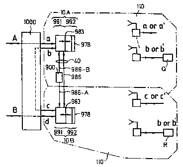
FIG. 6 shows an embodiment of a system where there is
'~0 a cooperation through a communication link 40, switchings
between subsystem internal intermediate couplings through a
switching function 900, for other traffic switchings and
between different connected signals through an external
switch function unit 1000. Through said unit 1000, which
can be considered as an example of an external network
WO 92/02996 PCT/SE91/00526
comprising for instance an independent "conventional"
digital switch or a similar apparatus, there are normally
traffic switching of traffic between subsystems or other
systems at the same or at other sites. The external switch
5 or corresponding apparatus can also be arranged to provide
switching functions corresponding to the function for said
schematically shown switching unit 900, which for instance
also can be utilized for redundancy, etc, in accordance
with what is stated about said unit 900, or if there are
10 lower or more limited requirements on for instance automa-
tic switchings in a system which could be arranged through
said unit 900. As an alternative other external digital
switches can be utilized for providing said switching
function 900. In said figure said unit 900 is illustrated
15 as a schematic function for switching information within
and between several subsystems. Said figure shows the
interaction between two subsystems but also more exist if
required. In a complex network comprising several, for
instance groups of subsystems, which can interact or
20 generate interference within each group, a switching
function 900 is formed for each group. Through the
switching function 900 of said CS unit connected signals
are switched to and from or between subsystems at demand.
Said switching function normally constitutes a switching
25 function which is closely integrated with each subsystem
and which can be controlled to interact with other desired
subsystems, in cases where said function is implemented.
This will provide for instance new fast alternative
switchings, transfer paths when detecting errors, traffic
30 blocking etc. Said switching function 900 is in other
accompanying drawings illustrated in a way showing that for
instance a switching between subsystems will occur in a
function or a unit which is common to more than one sub-
system.
WO 92/02996 PCT/SE91/00526
31
Required functions for digital switchings, logical
handling of each of the subsystems or group of subsystems
can also be considered as integrated with regard to for
instance function and unit where basic functions and units
included in this description are integrated. In such a case
the communication interface between a LFU and a HFU is
further described below for example an interface to and
from the switching system. This is shown schematically in
FIG. 6b.
A switching system 1001 includes within the system
thereof completely or partly integrated functions for for
instance concentration of traffic, logical handling of
information with PS units, and also switchings between
subsystems. The connection to external devices is provided
through a transparent communication interface 983 to each
HFU. In said figure the system can be considered to
comprise one to N subsystems. N 1 or more.
Said figures show primarily system implementations
where the systems constitute separate extended radio
network arrangements which in interaction with existing
networks, switching systems, etc, will provide separate
systems and units. This is beacuse the method can be
described more clearly and that models of this type can be
utilized in interaction, for instance as radio access
networks with existing systems of different types, and
because existing switches at the moment are not provided
with the desired functions. This type of systems can be
regarded as comparatively independant of supplier. Another
way of describing is to consider the method integrated with
a switching system. This is important because digital
switching systems normally are based on solutions which are
specific to the supplier. FIG. 6 shows schematically an
example of an implementation for transparent transmission
of connected signals through two subsystems, each of which
covering a service area. A digital signal a is to be trans-
WO 92/02996 PGT/SE91/00526
32
ferred from or to CS/PS partly or completely. Said signal a
is transferred for instance transparently between CS, PS if
this is desired. As an alternative only desired fragments
of said signal are transferred in dependance of traffic
demands, corresponding time frames in PCM multiplexed
signals, or cells in asynchronously multiplexed digital
signals, etc. When implementing the systems it is in some
cases optimal to connect subsystems to digital signals
having a substantially higher capacity than required by the
applications at the PS units. This applies for instance in
a system having CS units connected to CCITT standards in
Europe 8,34,155,565 Mbit/s, etc, synchronously or asyn-
chronously multiplexed or corresponding standards in other
parts of the world, and where said PS units for instance
are provided with a customer interface corresponding to
multiples of 64 kbit/s, for instance Basic, Primary ISDN,
etc. In such cases a connected signal at each CS unit
normally contains information to several PS units. In
systems which are connected through an external switching
system there can be internal switchings within a subsystem
or between subsystems, for instance through an external
switch 1000 according to FIG. 6. If a customer Q connected
in one subsystem l0A through an interface b needs to commu-
nicate with another customer in another, the same, or an
adjacent service area, said customer being connected under
another subsystem lOB through an interface d, this can be
done through said switch 1000. Traffic switchings are
provided for instance through an conventional external
switch or other type of traffic switching unit 1000 rather
than being incorporated as a part of the system even if it
basically is possible to accomplish the same through for
instance said switching function 900, if such a function is
included. Traffic between applications within a subsystem
and between other subsystems is provided through said
digital switching function 900. The reason for using a
WO 92/02996 PCT/SE91/00526
33
switching function that has to function for for instance
subsystems operating in parallel is that at demands fulfil
any requirements on fast switchings and also efficient
traffic management Within one and the same or adjacent
service areas. Normal operator controlled or customer
controlled traffic switchings within and between subsystems
and between systems normally take place through a separate
digital switching unit 1000. An external switching unit at
a site may constitute a switching function to a plurality
of CS units at the same site. At one site it may further
function as a switching unit to several subsystems termi-
nating at different sites. In cases where a subsystem is
structured in a repeating configuration said switching unit
can be utilized for traffic switching. Generally inputs and
outputs of the system are applied for transparent trans-
missions or other transmissions, normally implemented and
formed with a standard interface according CCITT syn-
chronuous capacity hierarchies including for instance 64
kbit/s, 2,048 and 1,544 Mbit/s. As an alternative lower or
higher transmission hierarchies or asynchronuous digital
signals such as SONET, SDIi, asynchronuous multiplexing,
ATM, etc, are applied. It is therefore possible to switch
traffic smoothly within each subsystem, between subsystems
or to and from other systems other digital "switching
units" existing on the market.
As a result of the time frame structure of the sub-
systems being formed in a modular way in a number of
equally large time gaps it is possible to handle an effi-
cient modular capacity such as a subamount up to a total
radio channel capacity to and from each PS or between CS
units. This provides a flexible and cheap implementation
for controlling varying digital amounts of traffic flow
within or between subsystems. In cases where an external
switching function is sufficient in a specific implementa-
tion of a system the internal switching function 900 could
WO 92/02996 ~~'~ PCT/SE91/00526
34
instead be provided through an external switch. That is, so
as to lower the amount of internal complexity of the
switching unit 900 in said central stations external
standard switching functions (corresponding to a digital
switch) are utilized at for instance a central terminating
point for internal or external traffic switching within
subsystems, between or to and from other systems, see FIG.
9 and FIG. 17. As an alternative such a switching is provi-
ded at a location where traffic for several sides termi-
nates in a so called central terminating point CTP. When
there are demands for an automatic working, for instance
for traffic blocking or other traffic interaction, for
instance if a customer connection is intended to be moved
to another cell or another sector, has to be automatic
between said subystems or part of said subsystems said
internal switching function 900 or a corresponding
switching function is utilized.
FIG. 7 shows another example of a schematic structure
of several subsystems. At the same site for instance one or
several CS units lOA,lOB,lON operating at a common frequen
cy band, can interact and handle traffic separately and
simultaneously in for instance a so called super central
station SCS. The traffic can be terminated in external
networks at each SCS. As an alternative the traffic for
external networks may be terminated at a central termina-
ting point CTP, which is common to several CS units or SCS
units, as described below. Where there are demands on
automatic, fast traffic switchings, switchings of parts of
connected signals, etc, the traffic is coordinated through
said switching functions 900,when such a function is imple-
mented.
FIG. 7a shows further examples of embodiments of PS
units so as to illustrate the structural flexibility. At
the top of the figure a PS without redundancy is shown. At
the centre there is shown a PS arrangement where two PS
WO 92/02996 PCT/SE91/00526
units are used alternatively for the transfer. The bottom-
most example shows how two PS units separately provide a
specific customers application 310 with a certain part of
the traffic capacity. For instance in a normal case the
5 application will provide a utilization of the capacity of
each of the PS units by for instance adding the capacity of
said PS units. If an error occurs the capacity of that PS
unit is lost. Any required signal processing and also
communication between two PS units, when such a communi-
10 cation is required, will take place through said unit 300.
The above description shows some possible embodiments. But
also more combinations are of course possible. Redundancy
is achieved when implementing a system at for instance
SCS/CTP 1100 by switching digital signals connected to 900
15 to an alternative CS. Thereby it is possible that different
CS units constitute redundancy to each other, thereby
having, taking over or switching in parallel traffic to a
present periferal station PS, that is while maintaining
traffic to the same PS or as an alternative to another, a
20 doubled or a redundant PS. In another shown example two PS
units are integrated for a closer integration and inter-
action.
FIG. 12 below shows how the structure of a PS will
provide interaction on several interface levels.
25 FIG. 8 shows schematically another embodiment where
communication between subsystems 2000 with a PS exists at
the same frequency band during different time periods To,
Tp with different CS units l0A and lON, respectively. A
switching function 900' between said subsystems is in this
30 case formed as an integrated part of a switch.
FIG. 9 shows examples of further alternative system
embodiments and how different systems or subsystems may
interact by general interfaces or switches. The example
shows how a first system 1200 operating at a frequency f2,
35 and a second system 1300 operating at a specific frequency
WO 92/02996 PCT/SE91/00526
3 6 ..
~ ~c~~
fl, and a repeating subsystem 1400 operating at fl can be
interconnected, for instance if an extension of the radio
covering area is necessary at for instance said frequency
fl. It is shown how traffic smoothly can be switched
between different systems 1300, 1400, 1200 through for
instance a separate switching unit 1000. Traffic in said
repeating system 1400 is denoted 70. The example is given
so as to illustrate some possible different structures and
embodiments of systems and subsystems. Furthermore, the
systems may comprise substantially more embodiments, for
instance having different radio channel rates, systems for
transparently transferring digital signals, systems for
mobile applications, possible alternative frequency
elections within each subsystem, alternative choise of
diversity methods such as polarization multiplexing, an
alternative technique of modulation, etc. The modular
structure of a CS and also the possibilities of a corre-
sponding structure for a PS provides also an extension of
the radio coverage over wide areas while maintaining a
terminating point by each new CS being connected to a PS
from another subsystem. So called repeating subsystems and
other systems having the same and different frequencies may
interact in traffic through similar terminating and user
interfaces through an external digital switching function
1000. Wide area networks can be created as a result of the
structure of said CS units with a separation in a high
frequency unit and a low frequency unit.
FIG. 21a and FIG. 21b show further example ~f
different embodiments and the interaction of a radio access
network and a connection network.
FIG. 10 shows as an example subsystems integrated
with a switch function. It is shown how previously shown
units/functions are integrated into one unit. 991' corre-
sponds to said LFU and provides functions corresponding to
the function of 991. IC relates to an interface into sub-
WO 9Z/02996 PGT/SE91/00526
37 2058993
systems. A communication 987-1' between a logical function
LC and LP illustrates the maintenance of control data on a
PS, specific distances, time periods, etc. Furthermore, the
communication 987-1' from LC illustrates control data for a
HFU 992. The handling of information with other PS units
through said interface 983 is represented by 983-IC.
Information interaction with a HFU is done through 983-LC.
It is not necessary to transfer control data for said HFU
through the radio system.
FIG. 11 shows schematically an example of one of
several possible time frames for a TDMA time duplex system.
The example is shown so as to give a general example of
how o form an opeating system in time duplex. Systems
implemented according to the present method are provided
with varying capacity, time sharing, time periods for CSSF
and PSSF, respectively, according to actual demands. For
two of the subsystems in the example the time frames are
formed for time duplex. In the example the transmitting
time in each direction has the same magnitude; in the
example it is assumed that the traffic volume in both
directions have the same magnitude. There could be a
difference in capacity in different directions, and the
frame structure is chosen in dependence of specific
applications, demands on time delay, etc. System having a
time duplex structure provides a simple and cheap method of
constructing, and a low or insignificant interference, or
an interference which cannot be measured, between adjacent
CS units when the CSSF, PSSF are synchronized in each of
the subsystems. Furthermore, such a system will provide a
smooth allocation of frequencies, an exonomic implementa-
tion of a PS, efficient utilization of radio channels in
applications having a dynamic traffic, etc. 1 ...n time
gaps are defined under each CSSF, and l...p, respectively,
for each PSSF.
WO 92/02996 PCT/SE91/00526
3e
~~'~'
Basically each CS unit communicates with a number of
PS units associated thereto. Each CS should be updated, for
instance about any athorized PS units existing within the
covering area associated thereto, be able to identify new
PS units, what traffic that has to be transferred, allocate
time gaps for traffic to/from each PS, PS requests and
status replies, detect the quality of the transfer. For
identifying, continuously synchronizing and controlling
each PS unit under each CS unit a possible example of a
system embodiment in time duplex is shown. A time period is
allocated in a transmitting frame of a CSSF, said time
period being referenced to as 1501. In PS time frames a
time period 1510 can be allocated for instance as a
response to an identity call. Said time period 1510 varies
in each case depending on a predicted interval of distances
between a CS and a PS, and also depending on the required
frequency of the process of identification. 1510 represents
the allocation of a time period for transmitting a reply on
an identity call for an appropriate equal adjustment of a
constant delay due to varying distances from different PS
units to each CS unit. Each PS is time compensated with
regard to the varying propagation time between a CS HFU and
each PS unit in each subsystem that said unit is communi-
cating with. Normally, the major part of available time is
utilized for transferring traffic (Information Packages IP
that is user data), or other control information (Control
Information Packages, CP, that is system signaling). Trans-
ferred packages that contain information and control data,
respectively, are separated among other things due to
different requirements on the transfer and detection of
information, and also actions based on the contents of each
of the types of packages. A CP has to be rapidly read and
detected with respect to quality. 1501 is an example of a
time period utilized for synchronizing information and/or
control. When synchronizing it is also possible to utilize
WO 92/02996 PCT/SE91/00526
39
~~~~~~J
a bit synchronizing information applied to any transferred
package. 1502 represents a time period for an identity
transmission call to PS units of other stations. Said time
periods 1501, 1502 can also be provided in a common time
gap or a common time interval, and the example shows a
possible system structure. In one and the same SCS a time
difference 1605 between time frames of different subsystems
basically becomes "zero" as a result of a frame synchroni-
zation. The basic synchronization between subsystems not
located at the same site but possibly interfering is
provided by coordinating said subsystems to minimize this
time period. If the average distance between CS units that
might interfere with each other is for instance 20-30 lan
said overlapping time period should be lower than approxi-
mately 1000 ns. If for instance time frames have an exten-
sion of 1-2 ms both for transmitting and for receiving the
probable loss due to interferences will be limited. Also
other combinations or frame times are possible. It is for
instance possible to apply a dynamically varying length of
the time frames in each subsystem according to a specific
traffic demand in time or according to other methods in
dependence of variations of traffic flow in different
applications and system embodiments. All mentioned time
periods, intervals and positions, etc, for the time frames
are only examples. Several different embodiments are
possible in different system structures.
FIG. llb shows further advantages by constructing a
system according to the present method. The overlapping
time 1605 between different subsystems, see FIG. lla,
should in a time duplex application be as small as
possible, at least for subsystems that may risk to generate
radio interference with each other. As to CS units at the
same site SCS this is readily overcome by frame synchroni-
zation. When applying the method in a case where several
SCS units terminate at a common point this could also be
WO 92/02996 ~~ PCT/SE91/00526
J
efficiently coordinated and compensated for at the CTP.
This is a further advantage with the structure method and
separation in LFU/HFU. SCS:s located at different distances
from each other are adapted by a time delay for decreasing
5 the overlapping between subsystemns. possibly interfering
with each other, in cases where it is desirable. This could
be achieved by connecting varying delay functions for each
CS, CSC to compensate for differences in propagation time
to have an adaption for different actual HFU units for
10 evening up relative differences of propagation time. That
is, specific HFU units can irrespective of the distance to
hFU unit be regarded as located at "the same" distance.
FIG. llb shows an example where a fibre network is
utilized as a transporting network to a plurality of spread
15 out HFU units, each of which covering one service area. DCC
stands for Digital Cross Connect. In the shown embodiment
the shown subsystems terminate in a central terminating
point CTP. Furthermore, it is shown how groups of HFU units
constitute SCS:s at common sites. The examples of the
20 description show time duplex systems. A number of advan-
tages exist with time duplex. The time interval for each
CSSF and PSSF can be optimized and made short so as to
compensate for a delay and any required intermediate
storing capacity. The frame structure could for instance be
25 provided with only one or a few number of time frames, etc.
A disadvantage with time duplex as compared to fre-
quency duplex, is that the transmission speed in a radio
channel is divided between two directions resulting in
switching losses, etc. Another disadvantage is that larger
30 memories for buffering purposes and intermediate storing
are required, for instance on the HFU, and also resulting
therefrom a time delay.
When applied in system embodiments implementing
systems for distribution of digital system flows according
35 to principles of ATM, or systems mostly integrated or con-
WO 92/02996 PCT/SE91/00526
41
nected to ATM switches having an asynchronuous multiplexing
or a similar switch, or transmission system, such as SONET,
SDIi, MAN; DQDB, etc, or similar to CCITT, ISO, IEEE,
etc, standard transmission systems, embodiments operating
in frequency duplex will provide a decrease of transmission
delay. Systems constructed in CDMA technique or in combina-
tions with TDMA having narrow band modulated signals in
frequency steps are formed for instance with utilizing one
or several time gaps for a time frame according to time
duplex or frequency duplex. As an alternative a varying
adaptive time interval length is applied for time gaps or
frame according to any application or any demands. For
instance in sporadic data traffic the method may provide
flexibility and a suffucient quality. Each application will
have different requiremnts on each system. The available
system capacity in time duplex is determined either to
provide at each set up of data transfer for a user a two
way connection between a CS and a PS which could be com-
pared to a circuit coupling in a telephone system. As an
alternatie there is allocated individually to each direc-
tion, in a time frame under 200 and 210, respectively, a
time gap with regard to the actual traffic needs. When
allocating transmission resources in a subsystem according
to demands for a CS-PS and a PS-CS, respectively, in any
direction in principle potentially more information can be
transferred over the system, if "silent" switching trains
can be utilized by others. The time gap allocation is con-
trolled and coordinated from a CS through a CP signalling
any required information to each PS. Basically each PS will
have almost a slave function under a CS. This means that
each PS will receive information about which time gaps to
be used and for what purposes. Through the signal channel
CP a PS also informs a CS the traffic needs existing at
present, which time gaps that are used at present and by
whom, status, etc. Through a signalling between each
WO 92/02996 PCT/SE91/00526
4 2 ._
subsystem or CS, PS any PS is controlled, coordinated and
superwised with regard to quality by the CS. In dependence
on the application, the quality requirements for each IP,
etc, codes possibly applied to the information are decoded.
When errors in the transmission are detected there is for
instance a change of time interval, diversity measure,
frequency exchange. As an alternative there is an exchange
of CS through a signal connection at a CTP between actual
LFU units for actual stations. When subsystems cover adja-
cent service areas and terminate in a CTP it is possible to
move a PS to alternative service areas or CS, for instance
when there is an interference from other sources, etc.
To provide a fast transparent setting up of connected
signals and to minimize the signal capacity specific sta-
tion parameters are stored at each PS. In the cases where a
fast traffic setup is required, for instance dynamically
speech controlled setups of a new time gap, there is a
prereservation of time, including error analyzes of
prereserved capacity. Actual data are updated and corrected
afterwards when conditions have changed. Any actual traffic
data, allocating of resources, etc, are stored intermedia-
tely and updated continuously in intervals in each PS.
Using low rate intervals to optimize the minization of
signal capacity and to maximize the stability connected PS
stations can continuously be requested and updated by a CS.
This means that several PS units can be connected in a
passive way without utilizing more than a fragment of the
capacity of the subsystems. If for instance a subsystem has
hundreds of time gaps available one or a few of them can be
utilized for thousands of PS units which are connected in a
passive way. Any actual transmission demands varying in
time are detected, and new time gaps are allocated if any
free gaps exist or in dependence of another priority. If
there is no time available in a subsystem an alternative
WO 92/02996 PCT/SE91/00526
43 20~8~93
transmission path can be chosen if for instance a spare CS
is connected.
FIG. 12 shows an example of a basic structure with a
plurality of subsystems , 1...N of equal type which are
implemented in a modular way in a system according to the
invention. Reference is first made to a subsystem 1. Said
system is drawn as a radio network that reserves capacity
for the transfer of user information to any chosen station
through so called normally unconcentrated connections 995-
1, which are analyzed by a traffic dynamic function 950-1
and by means of a logical function 980. A schematic func-
tion for a HFU 971-1 is shown for varying distances for
coordination. The central parts of a subsystem are
interface and terminating functions 950, a low frequency
unit 991, a high frequency unit 992, and whenever appli-
cable a transparent transmission link 983 between said low
frequency unit and said high frequency unit. Furthermore,
at demands there is also a specific switching function 900-
900' between subsystems for redundancy, etc. 900' indicates
that said function is integrated, for instance with an
external switch or is incorporated in a switching system.
A block diagram is shown for a HFU unit. At the left
side of said unit there is shown outgoing or incoming
radiobased communication to an actual subsystem, a transfer
of user data IP, and signalling CP between CS and other
stations. There is shown a PS 11 and a redundant configura-
tion of PS units 11/11' having a modular structure which is
basically similar to the structure of a CS. However, most
of the modules for a PS have other functions. Also other
embodiments than shown of a PS can exist in dependance of
the application. In a CS 950 corresponds to 316 in a PS,
HFU in CS by 991 in a PS 313. Said PS includes logical
functions 312 communicating with said logical function 980
of said CS. 311 referes to a control and supervision of the
control function of a PS. 319 refers to a PS interface
WO 92/02996 PCT/SE91/00526
__
44
towards a user application. In onr embodiment there is
shown for instance how the modular structure can be
utilized to make also two peripheral stations, for instance
separated physically iri a low frequency unit LFU and a high
frequency unit HFU, interact trafically through a switching
unit 300, or operate redundant in relation to each other.
Digital signals 995-1...N into and out of each subsystem or
system comprises synchronuously or asynchronuously multi-
plexed digital or other types of asynchronuous/synchronuous
digital standardized flows of information, normally in
digital form. The example shows the interaction With an
external communication system 1000. As an alternative the
radio communication system comprises, as shown above a unit
1001 integrated with a switching system. External switching
functions are for instance conventional digital switches
intended for fixed or mobile traffic, switches according to
ATM type, packet data switches, for instance according to
X.25, or similar, or Routers, Brouters, Bridges, etc, for
data networks etc. External systems are applied for
instance for transparent access networks. Integrated
systems having a switching system could for instance be
mobile communications networks. Time and space control is
for instance applied to networks such as GSM, narrow band
digital TDMA systems in USA, or corresponding systems in
Japan.
A PS without redundant functions comprises according
to the present modular structure a HFU unit 311, a LFU unit
317, and an interface and customer terminating unit 316.
The example shows a system where each unit 300 also could
interact traffically with a common interface unit 318 or
that they operate for instance in redundancy through each
other through their regular interfaces. As an alternative
each PS unit is formed as a station without said redundant
parallel coupling. Interaction between PS units is done in
a digital level so as to keep low the costs and provide
WO 92/02996 PCT/SE91/00526
45 ~~~~~~J
flexibility. Through for instance standardized interfaces
319 toward external units also traffic switching can be
done through external switching functions similar to a CS.
In for instance a case where a peripheral station is to be
utilized for fixed traffic in a system of general telecom-
munication traffic a similar structure can advantageously
be applied for the peripheral station. In a case where the
system is implemented for mobile applications, terminals
carried by a person, etc, or other applications Where a
compact design is required and the physical structure, etc,
is completely different, said peripheral station can have
another structure so as to fit to such an application. The
peripheral station is provided with different levels of
independancy according to different requirements of the
applications. Normally there is an allocation of resources
at the CS because then the PS unit can have a logically
simple structure and be substantially controlled by the CS.
The storing of required control information for incomming
and outgoing traffic data, for compensating distances, the
CS address, addresses, status, etc, is done at the PS.
Furthermore, functions for alternative antenna directions
towards different CS units, alternative polarizations,
alternative frequencies, or an actual sequence of frequency
steps, etc, can be included in different systems if
required.
To create a flexibility to different applications
standardized international number series for users and/or
stations are used. It should be possible to change in a
flexible way identities in the system. Applications of so
called smart cards on for instance the PS will make it easy
for the users to define in a flexible way alternative users
on a common hardware. One or several subsystems can when
required be coordinated, configured, etc, through common
functions 1005,1006. It should also be possible to include
remote connections. In cases of for instance cellular
WO 92/02996 PCT/SE91/00526
gg'~
t~~~ 4 6
applications it is sometimes interesting to measure the
volume of traffic flows through the radio network for
debiting purposes.
FIG. 13 shows schematically a system configuration
having a signal interface 995-1...N where the system
basically can operate as a separate network for other
external networks of a type for transferring connections
for for instance conventional synchronuously multiplexed
signals or asynchronuously multiplexed signals, or HDLC
type of data.
In this case the connection signals normally have a
total transmission capacity exceeding the capacity of the
radio system. In for instance a dynamic traffic allocation
the actual traffic data is applied to be transferred
through the system. In these cases normally each PS has a
signal interface 319, the capacity thereof being substan-
tially lower than the transmission capacity for the signal
in said interface 995-1...N of said CS unit, for instance
64, 384, 1,544, 2,048 Mbit/s, etc, or a higher or a lower
transmission capacity.
It is also possible to apply the system structure
with a function for applying information from data networks
with an interactive duration, capacity, etc, for packeting
at 991 to time gaps of the system for a transfer in system
shape, and then recreation at a PS in any desired shape.
FIG. 14 shows schematically a few of a plurality of
possible cases of interference between subsystems that
should be considered. If the side lobes of an antenna
system are 20 db lower than the main lobe there is normally
obtained approximately a 20 db higher wanted signal com-
pared to a not wanted signal from another subsystem.
Normally the effect is higher because two directed antennas
are used. If the system in the example transmits in time
duplex the interference to the receivers during transmis-
sion is neglectable for the same or adjacent sites when
WO 92/02996 PCT/SE91/00526
47
there is a frame synchronization. By an appropriate elec-
tion of the modulating and demodulating method, for
instance PSR, MSR, QAM, Slip-Code, "Spread Spectrum" having
for instance coded channels, CDMA, etc, in the shown system
embodiment and digital transmission it is thereby possible
to achieve a parallel operation of more than one subsystem
operating at the same site and basically covering the same
area. The receiving at a CS is expected to be more sensi-
tive to interference as a total than at a PS because a CS
normally will be disposed comparatively "high" and also
because the traffic converges there. To minimize inter-
ference beteween "packages", for instance through the ether
to/from different subsystems, such as a PS or a CS, the
energy level normally is controlled in each subsystem
either to a fixed value for a cell/sector or dynamically or
optionally adaptively according to quality demands. Systems
can be provided with a dynamic control of the energy level
from a CS towards associated PS units. As an alternative
the radio energy level of a cell or sector is controlled to
a constant value individually to each cell or sector~in a
cell pattern which is covered in a more complex way with
many cells covering a larger area because in some cases
there will be only minor effects of an increasing capacity
in total with a dynamic power control on a time gap level
from a CS. Corresponding facts apply for PS units, see the
example of 14b.
PS traffic in a subsystem 3010 might interfere with
PS traffic in another subsystem 3012. Traffic to/from a PS
3000 might for instance interfere with traffic to another
PS 3001. The pay signals are adapted to a level in the
example. If the distance to said unit 3000 is much shorter
than the level of the pay signal transmitted for said PS
unit 3000 lower than the pay signal for said PS unit 3001.
The result is less interference 3050. However, the risk of
disturbance by interference from a second subsystem increa-
WO 92/02996 Y~ PCT/SE91/00526
_~
4s
ses in 3000 if the energy level is higher for 3001.
However, there is an adaption and minimization in total of
the total energy that might interfere within the system or
with other systems. Furthermore, the "cell configurations"
can dynamically be adapted when the traffic capacity in-
creases. That is when extablishing a radio network initial-
ly the requirements of the customer could be to cover wide
areas. When new subsystems are applied later on and imple-
mented successively then for instance the radio power of
each subsystem could be lowered considering the new condi-
tions.
FIG. 14a-b show some of a plurality of possible typi-
cal interference cases between subsystems in an application
of the CS units at the same site. Two of the subsystems are
considered to cover basically the same geographic service
area. FIG. 14a shows antenna systems of two different sub-
systems, for instance operating within the same frequency
band. "Information packages" in a time gap associated to
each system will arrive basically simultaneously to sub-
systems at the same "site" if the same time gap is used.
Interference risks are calculated in advance for fixed PS
applications when considering time gap when for instance
the same frequency band is used. Different sizes of time
gaps in different subsystems would also affect the inter-
ference between different subsystems.
FIG. 14b shows how interference 3050 can occur
between subsystems at the PS receivers. Two PS units at
different distances in different subsystems can interfere.
An adjustment of the energy level or said two subsystems
can be made considering that a deteriorating influence
should be minimized to obtain an acceptable transmission
quality. It is possible to calculate in advance that a
direct signal to a PS 3000 might interfere with the signal
to a PS 3001, if the same time period is chosen for said
stations. This could be avoided either adaptively by
WO 92/02996 PCT/SE91/00526
49
~~~8993
correction or in advance. In fixed system applications the
geographic positions are fixed and it is therefore possible
to utilize a known geographic pattern to predict an inter-
ference risk and then avoid or make a correction by chosing
appropriate measures such as changes of time periods, of
polarization, etc.
The effects from for instance side lobes, etc, are
more difficult to predict, and interferences that cannot be
predicted can be corrected adaptively by changing time,
power, polarization, etc, when errors have been detected.
Also previously obtained information about interferences
can be utilized. It is for instance possible that the
system learns that in a certain position an interference
source is located and thereby avoiding that direction
during any time period of interference. The adaptive
control means that the antenna specification for a CS
antenna does not have to be extreme with regard to direc-
tivity when the modulation, etc, is chosen appropriately,
and the levels of the side lobes coordinated therewith for
obtaining an acceptable transmission quality is sufficient
in most telecommunication services.
FIG. 15 shows an example of a basic system in a
system which is separated from another network. The flow of
information for for instance asynchronuously multiplexed
signals 5010 is applied in a system embodiment. A cell is
denoted 5001, a header is denoted 5003, and a field of
information is denoted 5002. To illustrate an application
with synchronuous multiplexing such a system is indicated
at 5009. In frequency duplex the HFU unit is provided with
a filter 977, and in time duplex there is a switching
between transmitting time and receiving time. In the
example the HFU basically can be arranged to operate at one
or several pairs of frequency or one or more frequencies in
dependance on a specific embodiment. One or several cells
or parts of cells are applied to packages of information of
WO 92/02996 PCT/SE91/00526
said subsystem in dependance on the actual capacity of the
radio system. Corresponding facts apply for synchronuously
multiplexed digital signals, that is fragments 5001 of time
gaps for a connected signal are applied to one or a combi-
5 nation of time gaps which are applied to information
packages.
An asynchronuous, unmultiplexed signal having for
instance an amount of information 5004, 5005 varying in
time is illustrated as another example, 5011.
10 FIG. 15 also shows schematically a block diagram of a
HFU 992-1 for a subsystem. As previously mentioned a HFU
can include common functions for several subsystems, for
instance for a SCS. The information from logical function
of a LHU applies control data to the HFU through input
15 multiplexing of control data on a transparent digital flow
of bits 983 that is transferred in parallel with user data
from 995, which is to be transferred to a PS. In a control
unit 981 the HFU control data will be picked out and used
for control signalling for timing, direction or other
20 control at said HFU. In said subsystem said HFU 992-1 com-
prises a control unit 981, and a modulating unit 975-1 and
a radio transmitting unit 975-2. There is included also a
demodulating unit 976-1, and a receiving unit 976-2. The
basic difference between frequency duplex and time duplex
25 is defined by a unit 977. In the first case said unit is
constituted by a duplex filter and in the second case said
unit is constituted by a unit switching between a transmit-
ting mode and a receiving mode. Said control unit 981 is
also formed differently in accordance with the differences
30 between duplex and time duplex. Further differences are
that in time duplex there is a higher degree of interme-
diate storing between transmitting mode and receiving mode
at the HFU. Through control unit 981 there is a control of
the transmitting and receiving in the ether. Said unit
35 receives in turn information from the respective or asso-
WO 92/02996 PCT/SE91/00526
51
ciated system logical function of the subsystem positioned
in 991. It is also possible to provide a completely decen-
trialized embodiment having for instance a subsystem logic
with or without coordination with other sites at each site.
Control signals of the example are shown schematically at
981-1. The direction controlled antenna system 978 is con-
trolled to an intended direction during some period of
time. The arrows pointing upwardly at 981 relate to control
signals for transmission of data into or out of said sub-
system. One arrow is pointing downwardly after being
detected in said demodulator. Said arrow symbolizes control
information from PS unit that is directly utilized at said
HFU in cases where such a unit is applied. In embodiments
having equal TDMA time gaps information transmitted and
received through the ether and through a HFU can be con-
stituted by a certain amount of digital information.
Between each time gap time is normally reserved so as to
provide redirection of the antenna. The information in the
ether is constituted, besides of the original information
5001, for instance if a cell represents a time gap, of a
certain amount of extra information for the radio system
for synchronizing and similar information, such as a
specific radio protocol 230 which may be different for each
system embodiment depending on the application. If for
instance ATM is used the user information transferred in
the ether as a package can be constituted by a cell,
several cells, or parts of a cell depending on specific
requirements on for instance time delay, etc. Said IiFU can
also be arranged to control one or several radio channels
or antenna systems or modems or switches. That is, one or
several radio carriers might be active and also one or
several antenna systems in different directions for one or
a group of subsystems.
FIG. 16 shows some further examples among a plurality
of possible examples of a radio channel comprising a
WO 92/02996 ~~ PCT/SE91/00526
52
plurality of parallel multiplexed signals 9051. Further-
more, a radio channel can be constituted by combinations of
parallel and coded signals at the same frequency band 9050.
A can be considered to representent coded parallel signals
and B uncoded. At the buttommost part of said figure it is
shown how the radio'channel can comprise coded wide band
channels, such as "spread spectrum" with a separation of
channels by coding CDMA 1.
FIG. 17 shows examples of physical implementations of
CS units. It is clear that the method provides a flexible
and powerful interaction between systems that are implemen-
ted according to the method and other networks. There is an
integration with other wide band networks, such as fibre,
to provide a wide area coverage. A common communication
interface is established to several subsystems if required.
FIG. 17b shows several SCS's. All IiFU units terminate
through some kind of transparent communication network to a
CTP. The structure is provided in a modular and flexible
way in steps when implementing new sectors or cells, each
of which creating a new service area 110. A logical inte-
gration to and from other networks is done through
1000/1001.
FIG. l8a,b shows the modular structure in another
way. It is illustrated that different types of PS units
having different antenna systems can exist. One PS 11 is in
one embodiment constituted by a fixed directed antenna.
Another PS 12 comprises an antenna system which is direc-
table within a sector/cell or corresponding area. The
antenna can be directed towards any chosen CS or chosen
CSs. A PS 13 comprises an omni-direction antenna. A PS 14
comprises a PS antenna system which during different time
periods can generate a varying width of the antenna lobe.
FIG. 19 shows an embodiment of LHU functions and also
the integration thereof towards the exterior. There is also
an interface 5000 which in the embodiment is connected
WO 92/02996 PGT/SE91/00526
53
between an external switching system 1000 and a subsystem
interface function 950-1. Said subsystem comprises a
control function 980. Any allocation of time gaps in
different directions, identification, status requests from
PS units are made through said control function 980. The
information is transferred through said communication
interface 983 to different HFU units 992. When several HFU
units interact common multiplexing functions 998 can be
utilized for several CS units at for instance a SCS.
Traffic switchings between CS units are made integrated in
said subsystem interface function 950-1 or by means of a
separate switching function 950. The communication man-
machine takes place through 1006. In other applications
said communication can be provided at another level.
Functions 1009, 1009' constitute one or several control
functions for said systems or for an interactive coopera-
tion and coordination between subsystems. The communication
for cooperation, etc, between subsystems is handled through
a communication channel 986. The corresponding communica-
tion man-machine is handled in a similar way.
From FIG. 20a..e further possibilities for a flexible
and modular structure are apparent. A first part of said
figures, a...c, shows master system modules that have been
previously shown. When functions of said subsystems are
integrated in a switching system an integration to networks
is formed, see FIG. 20d. FIG. 20e shows how systems of
different type will cooperate with Batch other, for
instance at a CTP, through associated LFU units. One case
is an example of a frequency duplex system interacting with
a time duplex system.
FIG. 21 shows an example of a system where several CS
units interact by transferring information between sub-
systems. Several SCS units handle traffic with each other.
A few of said SCS units are terminated to an external
network. A system implementation for fixed traffic can be
WO 92/02996 PCT/SE91/00526
~~~ 5 4
based on the configuration shown below. Below a more
detailed description of a system provded with a frequency
band that one or several subsystems utilize, i.e. time
duplex, is shown. A robust modulation is supplied, said
modulation having a high degree of resistance to interfe-
rence, for instance QPSK, with an efficient detecting and
synchronizing, for instance differential detecting provi-
ding an economic and robust solution. As an alternative
other signal processing methods could be applied. The
interfaces for applied digital flows to/from CS units are
for instance multiplexed or asynchronuously multiplexed in
a conventional way, ATD, "framed or frameless", or in any
other digital form with varying rate that is synchronuous
or asynchronuous and also unmultiplexed. The customer
interfaces will vary according to demands and can for
instance have the same rate as a CS or a lower rate, and
can for instance both on a CS and a PS be 1,544 or 2,048
Mbit/s. The radio channel of each subsystem has a certain
digital transmission capacity. Said capacity can be shared
by geographically spread out users for transferring traffic
in both directions. In a case with an integrated switching
system said subsystem interface function 950 is considered
to be integrated in the present switching system. The
blocks shown therefor constitute functional blocks that are
integrated in a suitable physical shape and not necessarily
in separate physical units. The frame is divided into time
gaps. Said time gaps are made of equal size and represent
for instance a certain user capacity 8,16,32,56,64 kbit/s,
80 kbit/s, 128,144,156,160,192,284, etc. That is to have a
certain capacity for each transferred package in each sub-
system hormonizing with conventional transmission
standards. This will make an interaction with other
networks more easy. A specific factor for time duplex is
that the information to be transferred is buffered on both
sides before being transmitted. When the data after some
WO 92/02996 PCT/SE91/00526
time has been buffered it is transmitted in any direction
and during any time period. The method is repeated
continuously. Said control unit 981 for said radio and
antenna unit, etc, of said CS unit will handle any
5 associated direct control. Besides direction and time said
antenna system can also include a function for varying the
polarity or any other diversity measure. A corresponding
control is made at the peripheral station. Said control
unit of each of the PS units are in correspondance with the
10 CS units, but there is no need for a dynamic redirection
between different time gap intervals. Some functions, such
as change of polarization, etc, for fixed directed systems
will improve the total capacity and are implemented when
required. The frequency, the code, new fixed directions to
15 another central, etc, are included where it is applicable.
When PS units are used in mobile applications requiring for
instance directed antennas towards associated CS units such
functions are added. That is the shown function modules are
structured in accordance with the actual demand in a
20 suitable shape. It is clear that also hardware units of the
PS units and functions also for CS units may vary when
included To illustrate an embodiment a system is described
below, said system having a radio channel capacity in time
duplex of approximately 45 Mbit/s and one frequency band.
25 The time gap for each subsystem is for instance approxima-
tely 2 ms. For each transmitting time period and receiving
time period, respectively, the time period of a time gap
corresponds to approximately 160 Rbit/s at approximately
300 time gaps, each of which having an extension of 6 ms.
30 That is approximately 300 time gaps of each system can be
applied in each direction, if the capacity is chosen to be
of the same size in said both directions. By for instance a
time gap on SCSF, PSSF of 0,5 ms the time period of each
time gap is decreased to 3 microseconds and the capacity
35 thereof to approximately 80 Rbit/s. If coding is applied on
WO 92/02996 PCT/SE91/00526
56
the information or on the control information the capacity
for a traffic is lowered. Said approximately 300 time gaps
are used for customer information and for control data.
Basically all or most of said time gaps are used when a
favourable dynamic and adaptive correction possibility is
generated at interferences, collision risks with other
subsystems, etc. An advantage with time duplex as described
above compared to frequency duplex is that in a traffic
dynamic situation it is possible to have a flexible
utilization of idle period for another traffic. In a normal
conversation one person is normally silent while the other
one talks. It will be possible to have an economic imple-
mentation of a PS, etc. In mobile systems a flexible
"handover" can be created between subsystems without any
necessity of changing frequency when switching between
subsystems. ATM, Asynchronuous Transfer Mode, having
defined lengths of information packages and control
signalling, etc, is implemented for a time and space
control system when required, for instance for the transfer
of transparent flows as previously mentioned. A split up
utilization of a channel capacity up to maximum capacity is
flexible when modular structure of frame structures are
applied in the radio system. If each time gap on said radio
channel corresponds to a certain capacity, for instance 64
Rbit/s, and said capacity is substantially lower than the
total radio channel capacity modular dynamic speed rates
can be implemented to function to and from different appli-
cations for different customers of the system. For instance
modular subrates can be created from the 64 Rbit/s as
defined in the example as a multiple of the rate of the
time gap. For instance 32 Kbit/s can be obtained by trans-
mitting only every second time. A disadvantage with such an
embodiment is a higher delay. Such a principle can be
utilized to create a slow polling of several PS units, for
instance in a case where many stations are connected in a
WO 92/02996 PCT/SE91/00526
5~ ~0~8~93
network without any requirement of higher capacity, redun-
dancy, etc, or when customers not using the associated PS
not should load the system. To keep low the delay of trans-
mission flows through the systems for instance frequency
duplex can be applied instead of time duplex. Thanks to a
flexible modular structure in said networks information
that is applied to the system can be transmitted to said
high frequency unit HFU can be supplied in a flexible way
with control and time information if it is desirable to
separate said high frequency unit and said low frequency
unit. For ATM type signals such control information can be
applied in any desired cells of the bit flow. In a corre-
sponding way there could be a similar adaption between HFU
and LFU when utilizing other types of transmission through
other types of multiplexed signals. Thus, at said HFU parts
of the transmission flow are utilized for for instance
timing and controlling said high frequency unit such that
there is a control of time and direction, optionally the
energy, polarization, frequency, etc, at said HFU. Thus,
said HFU unit can be arranged as a controlled remote unit
without any demands of control function. Primarilly selec-
tions of time, directions, etc, are made at said LFU. While
several LFU units can terminate at the same location a
system control that is more superior can be provided at
that location without the necessity of transporting control
information between different control units of different
spread out HFU units. Systems can be provided with a con-
trolled or an automatic search for PS units from each CS.
When an automatic station identification process is to be
applied a PS, for instance being.moved from one region to
another, should be identified at the new location. This
could be done for instance when power is supplied or by
reception of an identification signal from any or from a
chosen CS, or when being started in any other way. When an
identification process is finished the PS unit identified
WO 92/02996 PCT/SE91/00526
__.
58
is defined as to direction and distance, and afterwards
said PS unit can handle traffic in the system. Sensing of
existance of new stations is done by transmitting requests
in different directions and then wait for a reply, and also
transmit any required basic data and successively traffic
data allocation, etc, from a PS to a CS. When a PS is
provided with an automatic identification, logging in, and
where several subsystems in a geographic area operate at
the same frequency band basically communication can be
established over an unlimited geographic area, should there
be provided a network with several CS units.
If an automatic sensing logging in is not applied a
manual initiation, for instance handled by an operator, can
be provided in alternative covering areas. A PS which is
arranged for communication at different frequency bands can
communicate with systems operating at different frequency
bands by chosing for instance a new local oscillator
frequency, etc. High frequency parts from each CS are
disposed on an appropriate location, for instance in a
tower, on roofs, in a satellite, etc. In such cases where
two or more CS units are provided to cover basically the
same geographic area each of the high frequency parts can
be disposed comparatively close together without any
deterioration of the system properties. This is possible
because they are coordinated, when required, to delimit the
interference between each other by not choosing directions
generating interference during the same time period. Said
high frequency part and said low frequency part are separa-
ted physically when required by a fibre link, a micro wave
link, satellite, light wave link, coax cable, etc. Field
termination can for instance be done through multiplex
units, a digital cross connect, DCC, etc. At a common
utilization of for instance one and the same terminating
point CTP by different subsystems there is an efficient
coordination of time differences between frames in
WO 92/02996 PCT/SE91/00526
59
different subsystems, a switching of traffic, calculations
of interferences, etc. Besides what is shown in the imple-
mentation embodiments the method basically can be integra-
ted into or cooperate with networks with existing systems
of such types as TDMA, FDMA, Spread Spectrum, or combina-
tions of said types for narrow band or wide band mobile
communications networks, such as for instance PCN, GSM,
DECT or similar systems in Europe, USA and Japan. When for
instance implementing the present method for GSM a so
called Base Transiever Station, BTS is provided with an
antenna system that can be coordinated as to direction and
time. The control function 981 of said HFU units are to
different levels adapted of independant switchings or
functions allowed by said control function 980 of the
subsystem. As an alternative the control function 981 is
coordinated by common control functions, 1009, 1009' in
several subsystems.