Note: Descriptions are shown in the official language in which they were submitted.
2 0 8 9 1 2 1
~,
. ...
DIAMOND FILM ~ G TOOL
Sl~v~ J. BROX
16513 NE 30th Court
Ridgefield, Washington 98642
FIELD OF THE INVENTION
The present invention is directed to fluted cutting
tools that contain, as a part of their cutting face, a diamond
film. The cutting tools, for example end mills, can be produc-
ed with shear angles of up to about 25~.
BACKGROUND OF THE INVENTION
The prior art is filled with a variety of cutting tools
of different designs and compositional make-up. Various *ypes
of diamond compositions have been used to improve the cutting
ability and wear of such tools. The most common type of dia-
mond used in cutting tools is a diamond compact. Diamond com-
pacts are a mixture of a binder such as cobalt and diamond pow-
der. Such diamond compact materials are relatively thick,
e.g. about 0.08~" (2.03 mm), and relatively short in length,
e.g. about 0.065" (1.65 mm) maximum. To install such diamond
compacts in flutes of, for example, an end mill, it is neces-
sary to remove a significant amount of the tool base material
that forms the flute, so as to form a pocket (channel) for the
insertion of the diamond compact. As a result of the removal
of the tool base material from the flute, the flute is weaken-
ed. To produce a tool with a shear angle of greater than 0~,
the flute must be angled which requires cutting away even more
of the flute material. The combination of the channeling of
the flute to accommodate the diamond compact and the angling
of the flute to create a shear angle weakens the tool and ren-
ders it incapable of being used in high shear applications.
Moreover, the diamond compact contains cobalt which may react
with the tool base material and cause the diamond compact to
~ ~r l n~ 1 na: ~nen ~u~-
! 20891 21
.. .
", ~
become overheated and wear away during use. As a result, a
diamond end mill has never been successfully marketed on a
large scale.
In one attempt to solve this problem, a fluted rotary
tool of cemented carbide in which the cutting part is coated
with a thin layer of polycrystalline diamond by a vapor phase
synthetic method has been developed. The problem with this
approach is that the adhesiveness between the cemented carbide
and the diamond film has not proven to be sufficient to pre-
vent stripping of the diamond film during use.
U.S. Patent No. 5,070,748 discloses helical fluted tools
which are a two-piece construction, i.e. the cutting portion
is formed by electrical discharge machining (EDM) ~ollowed by
packing in a polycrystalline diamond complex and hot isostatic
pressing to hold the complex in position. This blank is then
- ground to the desired finish geometry and brazed by standard
technology to a tungsten carbide shank which has been ground
concentric thereto. A major problem in this tool is that the
braze is being relied upon to absorb all the forces involved
in cutting and the braze can not and does not hold up. In
fact, in tests of tools prepared in accordance with this pat-
ent in composite machining applications, the tools failed very
prematurely due to braze failure. Also, in the composite
machining, the helix delaminated the composite material in the
direction of the helix - an unacceptable result.
U.S. Patent No. 5,020,394 discloses yet another method
to overcome the problem encountered by the prior art tools.
The tool is produced by forming, by a vapor phase synthesis
method, a polycrystalline diamond film on the surface of a sub-
strate which has been subjected to helical grinding; then sub-
jecting the product to chemical treatment to remove only the
substrate, brazing the resulting diamond film in a fluted form
to at least a part of the rake face of a tool base metal and
~F-2624 03/05/1992 - 2 -
208912~ ' -
then subjecting the brazed tool base metal to working of a
flank face to form a cutting edge. The tools produced are
very expensive due to the complex technology required and fur-
thermore a two-step brazing process is used which is both ex-
pensive and results in a poor quality bond.
Accordingly, it is an object of the present invention to
construct a fluted cutting tool with a diamond cutting surface
that is durable and inexpensive to manufacture.
It is another object of the present invention to con-
struct a fluted cutting tool with a diamond cutting surface
that has a cutting surface having a shear angle of greater
than Ov.
It is another object of the present invention to con-
struct a fluted cutting tool in which the angle of the rake
face (rake angle) can be readily adjusted.
DISCLOSURE OF THE INVENTION
Accordingly, the present invention is directed to a cut-
ting tool comprising a body member having an inner core and an
outer surface. The body member is fluted at least along a por-
tion of its length and contains at least two fluted sections.
The degree of fluting, the number of fluted sections, the
shape of the flute, and the length of the flute depends upon
the particular tool. Each of the fluted sections define a
wedge shaped section having a cutting face (rake face) and a
flank face which intersect each other. The cutting and flank
faces extend outwardly from the core of the tool body member
at which point the two faces intersect to the outer surface of
the body member.
The cutting surface is formed so that it has a shear ang-
le of 0~ or greater, preferably greater and up to about 25~.
As defined herein, "shear angle" is the angle between the
DF-2624 03/05/1992 - 3 -
U89121 '--
plane formed ~y the top portion or cutting edge portion of the
cutting face and a plane perpendicular to the work surface.
The cutting face contains a slotted channel or pocket at
about the cutting edge portion of the cutting face extending
parallel to and adjacent to the outer surface of the body mem-
ber. Within the slotted channel is disposed a polycrystalline
diamond film which is flush with the surface of the cutting
face above the slot portion of the slotted channel and flush
with the outer surface of the body member.
,
The diamond film can be produced in thicknesses of from
about 0.006 to 0.040" (0.3 to 2.03 mm). As a result, the chan-
neling of the fluted sections need not remove very much of the
body member material to accommodate the diamond film. The re-
sult is a stronger and more durable tool. In addition, the
slot enables the diamond film to be securely installed, making
for an extremely durable cutting surface.
While the concept of using a slotted channel filled with
a diamond film may be used with a variety of different tools,
it is particularly suitable for use with rounded or cylindri-
cal tools such as end mills (cut on sides and ends), router
bits (same as end mills but for higher speed operations and
with more clearance), drill bits (make hole of specified diam-
eter), reamers ~sizes and shapes a drilled hole), countersinks
(shapes the top or bottom of a drilled hole to accept a screw,
rivet, or other fastener), and the like~
BRIEF DESCRIPTION OF THE DRAWINGS
Fig. 1 is a side view of a cutting tool according to the
present invention.
Fig. 2 is a front view taken along line 2-2 of the tool
of Fig. 1.
DF-2624 03/0~/1992 - 4 -
Fig. 3 is an exploded front view of the slotted channel
of Fig. 2.
Fig. 4 is a front view of another cutting tool according
to the present invention.
Fig. 5 is a front view of still another cutting tool ac-
cording to the present invention.
DETAILED DESCRIPTION OF THE PREFERRED EMBODIMENTS
Referring to the drawings, Figs. 1-3, show an end mill
10 comprising a body member 11 having two fluted sections 12
and 14. Each fluted section has a cutting face (rake face) 16
and a flank face 18. As best shown in Fig. 3, in the cutting
face 16 at about the cutting edge portion 20 there is disposed
a slotted channel 22. The slotted channel 22 has a polycrys-
tal diamond film 24 disposed therein. Only the portion of the
diamond film extending the length x along the surface of the
cutting face 16 is not contained within the slot portion of
the slotted channel 22, which extends the distance y along the
cutting face 16. The slot portion is bounded on both sides
and along its bottom 23 by the material forming the body mem-
ber 11. The slot securely anchors the diamond film 24. As
best shown in Fig. 1, the slotted channel 22 extends a dis-
tance DL along only a portion of the fluted section. This
distance DL will depend upon the end use of the tool and the
length of the flute. For example, the distance DL could be
about equal to the length of t-he flute or, as shown, a length
less than the flute length. The diamond film 24 which is con-
tained in the slotted channel 22 may be a single piece or two
or more sections may be inserted. Presently diamond films of
the thicknesses described herein are available in lengths of
up to about 4l- (10.2 cm).
The slotted channel may be of any suitable length and
width. Generally the width of the slotted channel is of from
DF-2624 03/05/1992 - 5 -
B
'_ 2089121
a~ut o.olo to 0.040" (0.5 to 2.03 mm), and most preferably of
from about O.lS to 0.025" (0.75 to 1.27 mm). The length of
the slotted channel is of from about 0.25 to 4" (0.63 to 10.2
cm), more preferably of from about O.S to 2" (1.27 to 5.1 cm1,
and most preferably of from about O.S to 1.5" (1.27 to 3.81
cm). The slotted portion y is generally of from about 0.75 to
2" (1.88 to 5.1 cm) and the exposed cutting portion x is gener-
ally of from about 0.5 to 1.5" (1.27 to 3.81 cm).
The slotted channel design allows the diamond film to be
securely positioned in the tool, which results in a rugged
tool. Because the diamond film can be formed to thicknesses
of only from about 0.006 to 0.40" (0.3 to 2.03 mm), the slot-
ted channel width w can be kept to a minimum, resulting in a
structurally superior tool to those in the prior art. In ad-
dition, and as shown in Figs. 1 and 3, the cutting surface can
be formed to have a shear angle of greater than 0~, preferably
Qf about 5 to 25-, and most preferably of about 10 to lS~.
Fig. 3 shows a tool with a shear angle of about 15-. As a
result of the increased shear angle, the cutting efficiency of
such a tool is significantly improved over prior art tools
with shear angles of 0~.
The end mill of Figs. 1-3 is preferably manufactured by
first machining the slotted channels into a cylindrical body
member 11. This is done by conventional techniques such as
grinding, milling, or electrical discharge machining (EDM).
The fluted sections 12 and 1~ are then machined by a similar
technique. The diamond film is then formed and machined, pre-
ferably by laser cutting to specification, to enable it to be
fitted into the slotted channel 22. Then, the diamond film is
attached into the slotted channel, prefera~ly by a standard re-
active brazing technique using a reactive metal braze paste.
Reactive metal brazes are well known in the art and generally
are based upon silver, gold, palladium, and the like although
the chemical composition of the braze is not critical. In ad-
DF-2624 03/05/1992 - 6 -
dition to the above metals, the braze further contains a metal
capable of forming a carbide thereof at the interface with the
diamond film, such as Ti, Ta, Cr, Mn, etc. Such metals are
preferably present in an amount of about 0.5 to 10 vol. %.
The brazing is preferably carried out by a method using an
ordinary silver braze containing Ti or Ta in a controlled
atmosphere.
An alternative and less preferred method of adhering the
diamond film to the slotted channel entails coating the sur-
face of the polycrys~alline diamond film with a Ti film having
a thickness of about 0.5 to 2 microns, then coating it with a
Ni film having a thickness of about 1 to 10 microns by a PVD
method, and then brazing the film with an ordinary silver
braze.
The body member 11 of the tool 10 is preferably made of
a cemented carbide alloy, although any suitable tool material
such as steel may be employed. The body member preferably con-
tains about 9o to 95% of fine tungsten carbide having a grain
size of no more than about 1 micron and about S to 10 wt. %
cobalt. Other components such as tantalum, nickel, or hafnium
may also be incorporated.
The polycrystalline-diamond film may be manufactured by
any suitable technique known in the art which produces a dia-
mond material with sufficient toughness for use in tool appli-
cations, including microwa~e plasma chemical vapor deposition
(CVD) (generally described in Japanese Laid-Open Patent Appln.
No. 58-100494), neutral ion CVD methods tgenerally disclosed
in Japanese Laid-Open Patent Appln. No. 58-91100), plasma
torch technology, or arc-jet processing. It is presently pre-
ferred to employ the arc-jet method to form the polycrystal-
line diamond film. The type of apparatus used for the arc-jet
deposition is described, for example, in U.S. Patent No.
4,682,564.
DF-Z624 03/05!1992 - 7 ~
B
7 ~ ~
,
Presently known methods generally involve the dis-
sociation of hydrogen as a facilitating gas and methane as a
carbon source by heating the gases to a plasma state with a
hot wire, combustion torch, plasma torch, microwave source,
arc jet, and the like. The heating occurs in a partial vacuum
near the surface of a deposition substrate, such as silicon or
molybdenum, to cause diamond to form as a layer thereon.
The diamond film employed in the cutting tool is charac-
terized in that, although any polycrystalline diamond can be
used, for cutting tool applications films exhibiting a high
Young's modulus and a high thermal stability are preferred.
Preferably, the Young's modulus is greater than about 1000 GPa
and the thermal stability is greater than about 700-C. in air.
While an end mill is described in Figs. 1-3, the concept
of constructing a fluted tool with a slotted channel contain-
ing diamond film may be employed to make different end mills
which contains three or more flutes and other round tools such
as reamers, router bits, counter sinks, and drill bits.
.
For example, Fig. 4 shows a front view of an end mill 30
similar to that described in Figs. 1-3, but with three fluted
sections 32 instead of two as in Figs. 1-3. The fluted sec-
tions have cutting faces 33 and flank faces 34 with a slotted
channel 36 containing diamond film being disposed in the cut-
ting face 33.
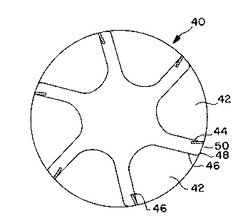
Fig. 5 shows a front view of a reamer 40 with five flut-
ed sections, each having a cutting surface 44 and a flank sur-
face 46. As shown, a slotted channel 48 contains a diamond
film S0.
The present invention will now be descri~ed with refer-
ence to the following Example, which should not be viewed as
limiting the invention.
DF-2624 03/05/1992 - 8 -
B
r
2089121
........ .
EXAMPLE I
An end mill of this invention was prepared. A cylindri-
cal tunsten carbide bar 4" (10.2 cm~ long and 0.5" (1.27 cm~
in diameter was machined by grinding to form two slotted chan-
nels at opposite sides of the cylinder. The slotted channels
were 0.035" (o.g mm) in depth, 0.020" (0.5 mm) wide, and 0.7s"
(1.9 cm) in length. The resulting substrate was then machined
by grinding to form two fluted sections each fluted section
had a cutting face 0.375" (0.95 cm) deep 1.125" (2.86 cm) in
length. Each cutting face was positioned so that the slotted
channel intersected the surface of the cutting face at about
the peripheral edges of the body member. The cutting face was
formed to possess a shear angle of 15~.
A polycrystalline diamond film was formed by the DC arc
jet deposition techniques substantially as described in U.S.
Patent No. 4,682,564. The film had a thickness of 0.018"
(0.46 m~), a Young's modulus of 1140 GPa and a thermal stabil-
ity of above 700~C. in air. The diamond film was laser cut to
the following dimensions: 0.04 x 0.75 inches (1 x 19.1 mm).
The diamond film was then brazed into each of the slotted chan-
nels by induction brazing in a controlled argon atmosphere
using a reactive braze containing silver-copper and titanium
at a temperature of about 900~C. The diamond film once in
place had an exposed surface 0.75" (19.1 mm) long that became
part of and flush with the surface of the cutting face.
To complete the preparation of the tool, the edge was
then ground to form a sharpened edge and to blend the diamond
film into the profile of the substate material.
EXAMPLE II
The performance of the end mill of Example I was compar-
ed with that of conventional end mills prepared from brazed
diamond grit compact tools in the machining of aerospace com-
posite materials which are laminates of carbon fiber reinforc-
DF-2624 03/05/1992 - 9 -
2089121
..... .
ed graphite. Conventional end mills containing a diamond grit
single layer, such as ~MsL~ of Norton company currently oper-
ate for edge finishing at a rate of about 20 to 40 inches (51
to 102 cm) per minute. These parameters cannot be exceeded
due to the amount of heat generated by the tools which causes
the tools to glaze and the composite part to glaze and delami-
nate.
In an initial test of the end mill of Example I, the
tool was operated at the same parameters as the conventional
tools. The finish on the composite part was judges to be su-
perior with the present tool.
In succeeding operations, the tool of Example I was oper-
ated at a rate of 2 times the existing parameters for such
tools. No heat build up was observed and the finish on the
part was excellent.
The tool was then operated at 3 and 4 times the existing
parameters, up to a final machine speed of 125 inches per min-
ute. No glazing, delamination or heat problems occurred. The
diamond thick film edge held up extremely well.
Accordingly, the tool of Example I produced a 4 times
greater benefit in composite machining per unit of time than
the prior art tools and a superior part finish.
DF-2~24 03/05/1992 - 10 -