Note: Descriptions are shown in the official language in which they were submitted.
2~ 3~
PORTABLE SHELF
Field of the Invention
This application relates to an adjustable-length
shelf which may be removably mounted in an enclosure, such
as a locker. The shelf is adapted for frictionally engag-
ing the locker sidewalls to support a load at a desired
vertical height within the enclosure.
Backqround of the Invention
Various adjustable-length shelves are known in
the prior art. United States patent No. 1,876,494, which
issued to Furo on 6 September, 1932, discloses an adjust-
able shelf consisting of two overlapping sections pivotally
coupled together. The lateral edges of the Furo shelf
sections are cut-away to provide spurs for penetrating
adjacent support walls when the shelf is mounted.
United States patent No. 4,155,312, which issued
to Thorkildson on 22 May, 1979, discloses a two piece shelf
which is telescopically adjustable in length. The lateral
ends of the Thorkildson shelf are flanged to facilitate
fastening the shelf to wooden structural members, as by
nails or screws.
United States patent No. 534,959, which issued to
Foster on 6 August, 1895, discloses a rack for books which
consists of two hingedly coupled sections. To install the
Foster rack, the end portions of the two shelf sections are
fitted into corresponding notches formed in the upright
shelf supports. The shelf is then pressed downwardly
toward a horizontal position until the two shelf sections
are brought in line with one another.
2039~ 38
- 2 -
All of the prior art shelves and racks referred
to above exhibit shortcomings which are overcome by the
applicant's invention. The primary shortcoming is the need
to permanently modify or deface the shelf supporting
surfaces, such as by forming notches in the support walls
for receiving the shelf ends or by mounting brackets and
the like on the support walls for receiving screws or other
fasteners. ^~
Further, none of the prior art shelving systems
are specifically adaptPd for mounting in an enclosure
having non-parallel sidewalls. For example, school and gym
lockers are often not perfectly rectangular in cross-
section and thus the end surfaces of conventional shelves
will not uniformly contact the interior locker sidewalls.
This limits the stability and load-supporting capacity of
such shelves and effectively prevents them from being main-
tained in position by frictional forces alone.
Accordingly, the need has arisen for an adjust-
able-length portable shelf which may be removably mounted
within an enclosure, such as a locker, at a desired height
without defacing or modifying the locker sidewalls.
Summary of the Invention
In accordance with the invention, there is
provided a shelf removably mountable within an enclosure
having generally opposed interior sidewalls, such as a
locker cabinet. The shelf includes a first section having
first gripping means for releasably engaging one of the
enclosure sidewalls, a second section pivotably coupled to
the first section, and a third section releasably coupled
to the second section and having second gripping means for
releasably engaging the other of the enclosure sidewalls.
The shelf is manually adjustable between a semi-collapsed
position wherein the first and second sections extend in
20~9~3~
-- 3
intersecting planes to facilitate placement of the shelf
within the enclosure and a deployed position wherein the
first and second gripping means engage respective enclosure
sidewalls and wherein the first, second and third sections
extend in a substantially common plane for supporting a
load.
;Preferably, the shelf includes coupling means for
releasably coupling the second and third sections together
and for adjusting the displacement between the second and
third sections so as to vary the overall length of the
shelf. Advantageously, the coupling means includes a prong
projecting from a central portion of the third section
which is insertable within a mating slot formed in a
central portion of the second section. The coupling means
may further include a pin insertable through apertures
formed in the prong and the second section for releasably
coupling the second and third shelf sections together.
-
20Preferably, the shelf second and third sections
; extend in a common plane when releasably coupled together
and the third section is pivotable relative to the second
section within such common plane to accommodate enclosures
having non-parallel sidewalls.
Each of the first and second gripping means
preferably includes a resilient gripping surface for fric-
tionally engaging the enclosure sidewalls. The gripping
surfaces are disposed on opposite ends of the shelf and
include elongated surfaces for uniformly distributing the
load to the enclosure sidewalls
Brief Description of the Drawinas
35In drawings which illustrate an embodiment of the
invention, but which should not be construed as restricting
the spirit or scope of the invention in any way,
~ 4 - 2 0 ~ 9 138
Figure l(a) is an isometric view of the assembled
shelf in its semi-collapsed position placed within an
enclosure, such as a locker cabinet;
Figure l(b) is an isometric view of the shelf of
Figure l(a) in its partially deployed position within the
enclosure;
Figure l(c) is an isometric view of the shelf of
Figures l(a) and (b) in its fully deployed position within
the enclosure;
Figure 2(a) is a side elevational view of the
shelf of Figure l(a);
Figure 2(b) is a side elevational view of the
shelf of Figure l(b);
Figure 2(c) is a side elevational view of the
shelf of Figure l(c~;
Figure 3 is an exploded view of the shelf of
Figure 1;
Figure 4 is a top, plan view of the shelf of
Figure 1 in its fully deployed position;
Figure 5 is a side elevational view of the shelf
of Figure 4;
Figures 6(a)-(d) are a series of fragmented, plan
views illustrating the adjustable end portion of the shelf
of Figure 1;
2~13$
- 5 -
Figure 7(a)-(e) are a series of fragmented,
longitudinal sectional views of the adjustable end portion
of the shelf of Figure 1;
Figure 8(a) is a top, plan view of the shelf of
Figure 1 in its fully deployed position installed within
an enclosure having diverging sidewalls; and
Figure 8(b) is a top, plan view of the shelf of
Figure 1 in its fully deployed position installed within
an enclosure having converging sidewalls.
Detailed Description of the Preferred Embodiment
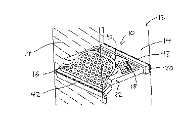
This application relates to a portable shelf lo
which is removably mountable within an enclosure 12 having
opposed interior sidewalls 14, such as a school or gym
locker. Shelf 10 may be used to support books, binders,
sporting equipment and the like.
The sequence of installation of shelf 10 is
illustrated in Figures 1 and 2. With reference to Figures
l(a) and 2(a), shelf lo is first placed within enclosure 12
in a semi-collapsed position at the desired vertical
height. Shelf 10 is then manually depressed as shown in
Figures l(b) and 2(b) until it assumes the fully deployed,
horizontal orientation shown in Figures l(c) and 2(c). In
the fully deployed position, the shelf end surfaces fric-
tionally engage adjacent sidewalls 14 of enclosure 12 to
securely maintain shelf 10 at the desired height.
As shown best in Figure 3, shelf 10 consists of
three separate sections 16, 18 and 20 which are assembled
together. Shelf sections 16 and 18 are pivotably coupled
with a pair of fasteners 22 insertable into apertures 24
formed in shelf sections 16, 18. Shelf section 16 is
pivotable relative to shelf section 18 about the axis of
2~913~
fasteners 22 between the semi-collapsed position referred
to above (wherein sections 16 and 18 extend in intersecting
planes) and the fully deployed position (wherein shelf
sections 16 and 18 extend in the same horizontal plane for
supporting a load). A stop plate 26 is provided on shelf
section 18 to prevent downward pivoting movement of shelf
section 16 beyond the horizontal plane of shelf section 18
in the fully deployed position.
In the preferred embodiment, shelf section 16 is
generally D-shaped and includes an arcuate inner end 28
which is received within a corresponding U-shaped cut-out
portion 30 formed in shelf section 18. Stop plate 26 is an
integral extension of the bottom wall of shelf section 18
which extends within cut-out portion 30 to limit pivotal
motion of inner end 28 of section 16 as described above.
Shelf sections 16, 18 together define a generally rec-
tangular load-supporting surface in the fully deployed
position (Figure 4). As should be apparent to someone
skilled in the art, shelf sections 16 and 18 of other
shapes and dimensions would function equally well.
In order to complete assembly of shelf 10,
sections 18 and 20 are releasably coupled together. Shelf
section 20 consists of an elongated body 31 having a prong
32 projecting laterally from a central portion thereof. As
best shown in Figures 4 - 7, shelf section 20 is coupled
to shelf section 18 by inserting prong 32 into a mating
slot 34 formed in a central portion of shelf section 18.
Prong 32 has a plurality of regularly spaced-apart aper-
tures 36 which are alignable with one or more mating
apertures 38 extending vertically through shelf section 18.
A pin 40 is provided for insertion into the aligned aper-
tures 36, 38 to releasably couple shelf sections 18, 20
together.
As shown best in Figures 6 and 7, the distance
between shelf sections 18, 20 (and hence the overall length
2~3'~ ~3~
of shelf 10) may be varied depending upon the extent that
prong 32 is inserted within slot 34. Accordingly, small
incremental adjustments may be readily made to vary the
overall length of shelf 10 to ensure that it fits snugly
S within the enclosure 12 in question.
As shown best in Figures 8(a) and (b), shelf
section 20 is pivotable from side to side relative to shelf
section 18 about the axis of pin 40. This allows shelf 10
to fit snugly within an enclosure 12 having non-parallel
sidewalls 14. The maximum extent of pivotable motion
depends upon the extent that elongate body portion 31 of
shelf section 20 is spaced apart from shelf section 18. As
shown in Figures 8(a) and (b), shelf section 18 may be
pivoted about prong 32 until the lateral ends of body
portion 31 contact the adjacent ends of shelf section 18.
This limited degree of pivotable movement enables adjust-
ment of shelf 10 to conform to the shape of enclosures 12
having diverging (Figure 8(a)) or converging (Figure 8(b))
sidewalls 14.
As shown best in Figure 3, the outer end surfaces
of shelf sections 16 and 20 are preferably covered with
gripping surfaces 42. Gripping surfaces 42 frictionally
engage an adjacent enclosure sidewall 14 when shelf 10 is
installed within enclosure 12 as shown in Figures 1 and 2.
Gripping surfaces 42 are constructed from rubber or any
other suitably resilient material which will not deface or
mark enclosure sidewalls 14.
The upper, load-supporting surfaces of shelf lo
may also be covered with a non-skid material having an
aesthetically pleasing pattern.
In operation, shelf 10 may be readily installed
in an enclosure 12, such as a school or gym locker, without
defacing or modifying the enclosure's interior sidewalls 14
2~913~
-- 8
and without the need for any tools or fasteners. As shown
best in Figures l(a) and 2(a), shelf 10 is first placed
within enclosure 12 in a semi-collapsed position with shelf
section 16 pivoted about the axis of fasteners 22. In the
semi-collapsed position, shelf section 16 extends in a
plain intersecting the plane of shelf sections 18 and 20.
This reduces the overall length of shelf 10 which facili-
tates placement of shelf 10 within the interior of enclos-
ure 12.
After shelf 10 is placed at the desired vertical
position within enclosure 12, the inner end 28 of shelf
section 16 is manually depressed as shown in Figures l(b)
and 2(b) so that it pivots downwardly toward a horizontal
orientation co-planer with shelf sections 18, 20. As the
inner end 28 of shelf section 16 is pressed downwardly,
gripping surfaces 42 covering the outer ends of shelf
sections 16 and 20 frictionally engage the enclosure
sidewalls 14.
Once the installer is satisfied that gripping
surfaces 42 are level, shelf section 16 is firmly pressed
downwardly until shelf 10 snaps solidly into the fully
deployed position shown in Figures l(c) and 2(c). As shelf
section is pressed downwardly, gripping surfaces 42 contact
sidewalls 14 with a sufficient degree of frictional force
to securely maintain shelf 10 at the desired height. In
the fully deployed position, inner end 28 of shelf section
16 contacts stop plate 26 on shelf section 18, thereby pre-
venting shelf section 16 from pivoting past the horizon-
tal.
Shelf 10 may be easily withdrawn from enclosure
12 in question by reversing the pivoting motion described
above (i.e. by pivoting shelf section 16 upwardly relative
to shelf section 18).
20~9138
g , .
If, after the initial installation, shelf 10 does
not snugly fit within the enclosure 12 in question, its
overall length may be incrementally adjusted as described
above by varying the extent to which prong 32 is inserted
within the corresponding slot 34 formed within the central
portion of shelf section 18. The installer need only
withdraw pin 40 from shelf section 18 by lifting it upward-
ly, and then realign prong apertures 36 with the appropri-
ate shelf aperture 38. Pin 40 may then be reinserted
through apertures 36,38 to securely couple shelf sections
18 and 20 together.
As shown in Figures 8(a) and 8(b), if the enclos-
ure 12 has non-parallel sidewalls 14, then shelf section
20 may be pivoted from side to side relative to shelf
section 18 to ensure that gripping surface 42 securely
engages the adjacent sidewall 14 along its entire length.
This ensures that shelf 10 exerts even pressure on opposed
sidewalls 14 which is critical to maintain shelf 10 secure-
ly in place.
When installed as aforesaid, shelf 10 is capableof supporting a substantial load without deflecting from
the fully deployed position. The inventor anticipates that
shelf 10 would be of use by students wishing to customize
the set-up of their school locker to suit their personal
needs. For example, shelf 10 could be used to support
books, binders or sports equipment. Since shelf 10 is
fully portable, it could be removed from the locker in
question at the end of the school term or season and used
in other lockers in subsequent years. Moreover, since
installation of shelf 10 does not permanently modify or
deface the interior sidewalls 14 of the locker, school
officials would likely not be opposed to its widespread
use.
.
':
2~9~38
-- 10 --
As will be apparent to those skilled in the art
in the light of the foregoing disclosure, shelf 10 could be
used in a wide variety of other applications. Many alter-
ations and modifications are possible in the practice of
this invention without departing from the spirit or scope
thereof. Accordingly, the scope of the invention is to be
construed in accordance with the substance defined by the
following claims.
.