Language selection

Search

Patent 2089236 Summary

Third-party information liability

Some of the information on this Web page has been provided by external sources. The Government of Canada is not responsible for the accuracy, reliability or currency of the information supplied by external sources. Users wishing to rely upon this information should consult directly with the source of the information. Content provided by external sources is not subject to official languages, privacy and accessibility requirements.

Claims and Abstract availability

Any discrepancies in the text and image of the Claims and Abstract are due to differing posting times. Text of the Claims and Abstract are posted:

  • At the time the application is open to public inspection;
  • At the time of issue of the patent (grant).
(12) Patent: (11) CA 2089236
(54) English Title: FEMORAL MEMBER OF A HIP JOINT ENDOPROSTHESIS
(54) French Title: MEMBRE FEMORAL D'UNE PROTHESE DE L'ARTICULATION DE LA HANCHE
Status: Expired and beyond the Period of Reversal
Bibliographic Data
(51) International Patent Classification (IPC):
  • A61F 02/36 (2006.01)
  • A61F 02/30 (2006.01)
(72) Inventors :
  • VECSEI, VILMOS (Austria)
  • HARDER, HANS ERICH (Germany)
  • OBERSTEINER, KARL (Switzerland)
(73) Owners :
  • MERCK PATENT GMBH
(71) Applicants :
  • MERCK PATENT GMBH (Germany)
(74) Agent: SMART & BIGGAR LP
(74) Associate agent:
(45) Issued: 1999-06-01
(22) Filed Date: 1993-02-10
(41) Open to Public Inspection: 1993-08-12
Examination requested: 1994-06-24
Availability of licence: N/A
Dedicated to the Public: N/A
(25) Language of filing: English

Patent Cooperation Treaty (PCT): No

(30) Application Priority Data:
Application No. Country/Territory Date
G 92 01 646.4 (Germany) 1992-02-11

Abstracts

English Abstract


A femoral member of a hip joint endoprosthesis, comprising
a shaft having a medial and lateral side which both are
arcuately rounded in cross-section and having a proximal
portion which is provided with openings connecting the
dorsal side with the ventral side, wherein the diameter of
the openings normal with the respect to the shaft axis
decreases from proximal to distal, whereby the distal
shaft portion is formed approximately straight, that at
least the openings adjacent the proximal shaft end are
formed as approximately parallel elongated holes, which
longer axis extends under an angle to the axis of the
distal shaft portion approximately vertical with respect
to the medial side proximally slightly curved..


Claims

Note: Claims are shown in the official language in which they were submitted.

THE EMBODIMENTS OF THE INVENTION IN WHICH AN EXCLUSIVE
PROPERTY OR PRIVILEGE IS CLAIMED ARE DEFINED AS FOLLOWS:
1. A femoral member of a hip joint endoprosthesis, comprising a shaft
having a medial and a lateral side which both are arcuately rounded in cross
section and having a proximal portion which is provided with elongated holes,
connecting the dorsal side with the ventral side, wherein the longer diameter of at
least the first elongated holes adjacent to the proximal end of the shaft extends
substantially transverse to the axis of the shaft decreases from the proximal to the
distal end of the shaft, the distal portion of the shaft being formed approximately
straight, characterized in that only the proximal portion is provided with four to six
approximately parallel elongated holes with the longer diameter thereof extending
under an angle to a transverse line of the axis of the distal shaft portion between
55° and 65°, and approximately perpendicular to the medial side of the shaft
which is proximally slightly curved, in that further the longer diameter at least of
the first elongated holes adjacent to the proximal end of the shaft is equal to or
larger than twice the width of the holes, in that the holes are freely open for the
accommodation of spongiosa, and in that the lateral side of the shaft is
substantially straight in distal-proximal direction.
2. The femoral member of claim 1, characterized in that webs are
located between the openings and the webs have a width which is smaller than
the width of the openings.
-7-

3. The femoral member of claim 1 or 2, characterized in that the distal
shaft portion has an approximately circular or oval cross section.
4. The femoral member of one of claims 1 to 3, characterized in that
the dorsal and the ventral side of the proximal shaft portion are flat and include a
small angle towards medial.
5. The femoral member of one of claims 1 to 4, characterized in that a
coaxial bore extending through the complete shaft is formed in the distal shaft
portion.
6. The femoral member of claim 5, characterized in that the bore ends
proximally in a projection of the shaft which extends approximately perpendicular
to the bore.
7. The femoral member of one of claims 1 to 6, characterized in that
the shaft is covered with hydroxylapatit in the region of the elongated holes.
8. The femoral member of one of claims 1 to 7, characterized in that
the shaft is made of a chromium cobalt or titan alloy by molding.
-8-

9. The femoral member of claim 1 wherein said longer diameter thereof
extends under an angle to a transverse line of the axis of the distal shaft portion at
60°.
-9-

Description

Note: Descriptions are shown in the official language in which they were submitted.


-- 2089236
A FEMORAL MEMBER OF A HIP JOINT ENDOPROSTHESIS
The invention relates to a femoral member of a hip joint
endoprosthesis according to the preamble of claim 1.
Conventional endoprostheses for the hip joint mostly have a
solid shaft which is straight or bent and which is anchored
in the femur canal with or without bone cement. Femoral mem-
bers implanted using bone cement are difficult to surgically
remove when they become loosened, for example. Shafts
implanted free of cement generate a frictional connection
between the shaft and the bone which sometimes results in
substantial tensions in the bone canal. EP-A 0 309 662 or
EP-A-0 243 585 disclose prosthesis shafts having a box-like
profile, where-in the cavity is accessible from outside
through dorsal and frontal openings. The cavity may be
filled with endogenic spongiosa to facilitate the taking of
the prosthesis in the femur by a genuine bony connection to
obtain a safe anchoring which is maintained for a long time.
A box-like shaft profile undoubtedly has an increased
elasticity so that the deformability of the materials
approaches each other in the boundary region between the
prosthesis shaft and the bone. On the other hand, there is
the danger that locally high tension peaks develop which are
detrimental to the stability of the shaft. This, however,
can be counter-acted by molding the shaft as disclosed in
EP-A 0 309 662. US-A-3 466 670 discloses a bent, relatively
slim hip pros-thesis having circular openings in the
proximal shaft portion extending from ventral to dorsal,
wherein the diameter of the openings decreases towards
distal. The openings have the purpose to reduce the weight
of the shaft.

-- 2089236
It is the object of the invention to provide a hip joint
endoprosthesis to be implanted free of cement which femoral
member affords a best possible connection between the
femoral member and the bone while providing a sufficient
stability of the prosthesis and a simple operation.
The object is solved by the features of claim 1.
The femoral member according to the invention has a distal
portion which is approximately straightly shaped, wherein
the cross-section of the distal portion is approximately
circular or oval according to an embodiment of the inven-
tion. The proximal portion of the shaft has approximately
parallel elongated holes, of which the longer axis extends
under an angle to the axis of the distal shaft portion,
approximately vertical to the medial side of the shaft
proximally slighty bent. According to a further embodiment
of the invention four to six openings of this type are
provided, preferably five. The angle of the longer axis of
the elongated holes is between 55 and 65~, preferably about
60~ with respect to a transverse line of the shaft axis. The
elongated holes are relatively long and at least the three
elongated holes adjacent the proximal shaft end have a
length which is equal or longer than twice its width. In a
still further embodiment of the invention the width of the
webs between the openings is relatively small, preferably
smaller than the width of the openings. The length of the
larger openings is at least half as long as the width of the
shaft in the region of the openings.
The arrangement and angular position of the openings results
in an optimum pressure distribution in the proximal shaft
portion. Furthermore, relatively large cavities to be filled
up with spongiosa are provided for metaphysar stabilization.

2089236
According to a further embodiment of the invention the
lateral side of the shaft extends approximately straight,
whereas the shaft is proximally slightly bent on the medial
side. Such a shaft which is relatively slim facilitates a
simple operation and a standardization of the shaft for a
variety of applications. Laterally and medially the shaft
comes in contact with the wall of the femur widened by
drilling. The distal shaft portion has a central bore thus
unloading the medullary canal. In a further embodiment of
the invention the central bore may extend through the
complete shaft and still further may end in a proximal
projection which extends approximately vertical to the bore.
The projection is further used as impact face in driving
home the prosthesis shaft. By means of the central bore a
lance may be used as an inserting means. The lance is
anchored in the bone before the prosthesis shaft is driven
home and thus affords a guide while the shaft is being
driven. Proximal the bore preferably has an internal thread
which is used for mounting an impact device for example, or
for mounting an extracting tool.
According to a further embodiment of the invention the shaft
is covered with hydroxylapatit in the region of the openings
to afford a more effective taking. The shaft may be made of
a suitable body-compatible material, preferably in molding.
Preferably a chromium cobalt or titan alloy is used.
An embodiment of the invention is now described with
reference to the drawings.
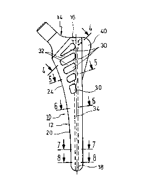
~ig. 1 shows the ventral and dorsal side of a femoral
member of a hip joint endoprosthesis according to
the invention,
Fig. 2 shows the lateral side of the femoral member of
Fig. 1,

-- 208923fi
Fig. 3 shows a similar view of the proximal shaft
portion, partly in section,
Fig. 4 shows a section of the illustration of Fig. 1
along line 4-4,
Fig. S shows a section of the illustration of Fig. 1
along line 5-5,
Fig. 6 shows a section of the illustration of Fig. 1
along line 6-6,
Fig. 7 shows a section of the illustration of Fig. 6
along line 7-7,
Fig. 8 shows a section of the illustration of Fig. 1
along line 8-8.
The femoral member 10 shown in Figs. 1 to 3 has a shaft 12
and a collar 14. The collar is not described in more detail
since it is conventional. As shown, the shaft 12 merges into
the tapered neck portion without forming a collar. There-
between, a projection 16 is formed laterally with respect
to the neck portion, which projection functions as an impact
surface for driving home the femoral member. The projec-
tion 16 or, respectively the impact surface, extend appro-
ximately vertical to the axis 18 extending through the
shaft 10.
As shown, the lower third (distal portion) shown at 20 is
shaped approximately straight, having an approximately
circular or approximately oval cross-section as shown in
Figs. 6 to 8. As shown in Fig. 1, the complete lateral side
which cross-section is arcuately bent in the remaining
portion, extends straight up to the projection 16. The
proximal shaft portion 24 is, however, medially slightly

~ O ~ g 2 3 ~
arcuately bent as shown in Figs. 1 and 3. Frontal side 26 and dorsal side 28 areflat (Figs. 4 and 5) and include medially a very small angle.
The proximal shaft portion 24 has five openings 30 extending from
the ventral to the dorsal side. The four upper holes 30 of Fig. 1 are shaped as
elongated holes, wherein the three central openings 30 have an approximately
rectangular cross-section. The uppermost opening 30 is shaped approximately
triangular and increases in width towards lateral. The longer axes of the
elongated holes 30 approximately extend under an angle of 60~ to the axis 18.
The lowermost opening 30 is an elongate hole of which the longer axis is parallel
to the axis 18. As shown, the openings 30 approximately end in an equal distancefrom the medial and the lateral side. The length is at least half as large as the
width of the shaft portion 24 in this region. The webs 32 between the openings 30
are relatively small. In the illustration they are smaller than half the width of the
openings 30. The centers of the openings 30 are located on a bent curve which
smoothely merges into the axis 18 in the distal portion 20. The length of the three
upper elongated holes is larger than twice the width of the openings 30. A largereceiving space for spongiosa results, but the stability of the shaft is not worsened.
The angular location of the openings 30 affords a fair pressure distribution in the
shaft 10. A bore 34 through the shaft 12 extends coaxially with respect to the
distal portion 10, which bore 34 proximally ends in the impact surface 16. As
shown in Fig. 3 the bore 34 is broadened at 36 and bears an internal thread for
receiving a tool. The bore portion 36 can be closed by a screw after driving home
the femoral member 10, wherein the head of a screw may be mounted flush in the
74855-6

~ O ~ ~ 2 3 ~
broadened portion 38. The bore 18 affords driving home the femoral member 10
by means of a guide lance which has been driven in the femur before.
- 5a -
74855-6

- 2089236
Laterally the proximal portion 24 has a web 40 to secure the
implanted femoral member 10 against rotation.
The femoral member 10 is made of a suitable body-compatible
alloy, for example a chromium cobalt alloy or, preferably, a
titan alloy be molding. The member is made in a set of
stepped lengths and diameters.

Representative Drawing
A single figure which represents the drawing illustrating the invention.
Administrative Status

2024-08-01:As part of the Next Generation Patents (NGP) transition, the Canadian Patents Database (CPD) now contains a more detailed Event History, which replicates the Event Log of our new back-office solution.

Please note that "Inactive:" events refers to events no longer in use in our new back-office solution.

For a clearer understanding of the status of the application/patent presented on this page, the site Disclaimer , as well as the definitions for Patent , Event History , Maintenance Fee  and Payment History  should be consulted.

Event History

Description Date
Inactive: IPC from MCD 2006-03-11
Time Limit for Reversal Expired 2003-02-10
Letter Sent 2002-02-11
Inactive: Late MF processed 2001-06-20
Letter Sent 2001-02-12
Grant by Issuance 1999-06-01
Inactive: Cover page published 1999-05-31
Inactive: Final fee received 1999-03-01
Pre-grant 1999-03-01
Notice of Allowance is Issued 1999-01-15
Letter Sent 1999-01-15
Notice of Allowance is Issued 1999-01-15
Inactive: Status info is complete as of Log entry date 1999-01-11
Inactive: Application prosecuted on TS as of Log entry date 1999-01-11
Inactive: Approved for allowance (AFA) 1998-11-16
All Requirements for Examination Determined Compliant 1994-06-24
Request for Examination Requirements Determined Compliant 1994-06-24
Application Published (Open to Public Inspection) 1993-08-12

Abandonment History

There is no abandonment history.

Maintenance Fee

The last payment was received on 1999-01-28

Note : If the full payment has not been received on or before the date indicated, a further fee may be required which may be one of the following

  • the reinstatement fee;
  • the late payment fee; or
  • additional fee to reverse deemed expiry.

Patent fees are adjusted on the 1st of January every year. The amounts above are the current amounts if received by December 31 of the current year.
Please refer to the CIPO Patent Fees web page to see all current fee amounts.

Fee History

Fee Type Anniversary Year Due Date Paid Date
MF (application, 5th anniv.) - standard 05 1998-02-10 1998-01-21
Registration of a document 1998-03-14
MF (application, 6th anniv.) - standard 06 1999-02-10 1999-01-28
Final fee - standard 1999-03-01
MF (patent, 7th anniv.) - standard 2000-02-10 2000-01-18
Reversal of deemed expiry 2001-02-12 2001-06-20
MF (patent, 8th anniv.) - standard 2001-02-12 2001-06-20
Owners on Record

Note: Records showing the ownership history in alphabetical order.

Current Owners on Record
MERCK PATENT GMBH
Past Owners on Record
HANS ERICH HARDER
KARL OBERSTEINER
VILMOS VECSEI
Past Owners that do not appear in the "Owners on Record" listing will appear in other documentation within the application.
Documents

To view selected files, please enter reCAPTCHA code :


To view images, click a link in the Document Description column. To download the documents, select one or more checkboxes in the first column and then click the "Download Selected in PDF format (Zip Archive)" or the "Download Selected as Single PDF" button.

List of published and non-published patent-specific documents on the CPD .

If you have any difficulty accessing content, you can call the Client Service Centre at 1-866-997-1936 or send them an e-mail at CIPO Client Service Centre.


Document
Description 
Date
(yyyy-mm-dd) 
Number of pages   Size of Image (KB) 
Description 1998-10-21 7 228
Claims 1998-10-21 3 69
Description 1994-02-04 6 192
Claims 1994-02-04 2 59
Abstract 1994-02-04 1 19
Drawings 1994-02-04 1 21
Representative drawing 1999-05-24 1 7
Courtesy - Certificate of registration (related document(s)) 1998-06-15 1 116
Commissioner's Notice - Application Found Allowable 1999-01-14 1 163
Maintenance Fee Notice 2001-03-11 1 176
Late Payment Acknowledgement 2001-07-03 1 171
Maintenance Fee Notice 2002-03-10 1 179
Correspondence 1999-02-28 1 38
Fees 2001-06-19 2 72
Fees 2000-01-17 1 41
Fees 1995-11-01 1 50
Fees 1996-11-05 1 55
Fees 1994-10-30 1 41
Prosecution correspondence 1994-06-23 1 36
Prosecution correspondence 1997-07-31 2 69
Prosecution correspondence 1994-07-20 1 38
Prosecution correspondence 1998-02-22 1 17
Prosecution correspondence 1998-09-27 1 37
Examiner Requisition 1997-02-03 3 145
Examiner Requisition 1997-08-28 2 54
Examiner Requisition 1998-03-26 2 49
Courtesy - Office Letter 1993-04-29 1 45
Correspondence related to formalities 1993-06-15 1 42
Correspondence related to formalities 1993-09-23 2 73
Correspondence related to formalities 1994-04-06 7 223
Courtesy - Office Letter 1993-12-01 1 16
Courtesy - Office Letter 1994-05-24 1 17
Correspondence related to formalities 1994-05-29 1 41
Courtesy - Office Letter 1994-11-08 1 14
Courtesy - Office Letter 1995-05-01 1 28
Prosecution correspondence 1993-02-09 2 75
Prosecution correspondence 1993-02-09 13 482
Prosecution correspondence 1994-07-20 2 55