Language selection

Search

Patent 2089313 Summary

Third-party information liability

Some of the information on this Web page has been provided by external sources. The Government of Canada is not responsible for the accuracy, reliability or currency of the information supplied by external sources. Users wishing to rely upon this information should consult directly with the source of the information. Content provided by external sources is not subject to official languages, privacy and accessibility requirements.

Claims and Abstract availability

Any discrepancies in the text and image of the Claims and Abstract are due to differing posting times. Text of the Claims and Abstract are posted:

  • At the time the application is open to public inspection;
  • At the time of issue of the patent (grant).
(12) Patent Application: (11) CA 2089313
(54) English Title: BOOT BINDING SYSTEM FOR A SNOWBOARD
(54) French Title: SYSTEME DE FIXATION DE CHAUSSURE POUR PLANCHE A NEIGE
Status: Deemed Abandoned and Beyond the Period of Reinstatement - Pending Response to Notice of Disregarded Communication
Bibliographic Data
(51) International Patent Classification (IPC):
  • A63C 10/00 (2012.01)
  • A43B 05/04 (2006.01)
  • A63C 09/00 (2012.01)
  • A63C 10/12 (2012.01)
(72) Inventors :
  • JESPERSEN, RANDY (Canada)
(73) Owners :
  • RANDY JESPERSEN
(71) Applicants :
(74) Agent: DOUGLAS B. THOMPSONTHOMPSON, DOUGLAS B.
(74) Associate agent:
(45) Issued:
(22) Filed Date: 1993-02-11
(41) Open to Public Inspection: 1994-08-12
Availability of licence: N/A
Dedicated to the Public: N/A
(25) Language of filing: English

Patent Cooperation Treaty (PCT): No

(30) Application Priority Data: None

Abstracts

English Abstract


ABSTRACT OF THE DISCLOSURE
A boot binding system for a snowboard includes a rigid
heel support adapted for attachment to a heel of a boot. The
heel support has a protruding member. A rigid ankle support
is provided which is adapted for attachment along a rear seam
of a boot. The ankle support is pivotally secured to the heel
support, such that the ankle support pivots laterally, and
flexes forwardly, while providing rigid support rearwardly.
A heel binding is provided having an overlay member which
overlays the protruding member thereby preventing the heel of
the boot from being raised. A toe binding is provided which
is adapted to secure a toe of a boot to a snowboard thereby
preventing the protruding member from being moved relative to
the overlay member.


Claims

Note: Claims are shown in the official language in which they were submitted.

THE EMBODIMENTS OF THE INVENTION IN WHICH AN EXCLUSIVE
PROPERTY OR PRIVILEGE IS CLAIMED ARE DEFINED AS FOLLOWS:
1. A boot binding system for a snowboard, comprising:
a. a rigid heel support adapted for attachment to a heel
of a boot, the heel support having a protruding member;
b. a rigid ankle support adapted for attachment along a
rear seam of a boot, the ankle support being pivotally secured
to the heel support, such that the ankle support pivots
laterally, flexes forwardly, while providing rigid support
rearwardly;
c. a heel binding having an overlay member which overlays
the protruding member thereby preventing the heel of the boot
from being raised; and
d. a toe binding adapted to secure a toe of a boot to a
snowboard thereby preventing the protruding member from being
moved relative to the overlay member.
2. The boot binding system for a snowboard as defined in Claim
1, the overlay member being a generally "U" shaped member.
3. The boot binding system for a snowboard as defined in Claim
1, the ankle support being positioned in an elongate pocket
along the rear seam of the boot.
4. The boot binding system for a snowboard as defined in Claim
2, the protruding member having a channel adapted to receive
the generally "U" shaped overlay member.
5. The boot binding system for a snowboard as defined in Claim
2, the generally "U" shaped member having threaded end
portions, the snowboard having threaded apertures, and a
coupling member being used to attach the generally "U" shaped
overlay member to the snowboard, the coupling member having a
bolt-like male end and a nut-like female end, the male end
being insertable into the threaded apertures, the female end
receiving the threaded end portions of the generally "U" shaped

members, the coupling member having threads cut in opposing
directions such that as the coupling member is rotated the
coupling member is drawn into the apertures in the snowboard
while concurrently the threaded end portion of the generally
"U" shaped overlay member is drawn into the female end of the
coupling member.

6. A boot binding system for a snowboard, comprising:
a. a rigid heel support adapted for attachment to a heel
of a boot, the heel support having a protruding member with a
channel; (1) a rigid ankle support adapted for insertion
in an elongate pocket positioned along a rear seam of a boot,
the ankle support being pivotally secured to the heel support,
such that the ankle support pivots laterally, flexes forwardly,
while providing rigid support rearwardly;
b. a heel binding having a generally "U" shaped overlay
member which wraps around the heel of the boot and overlays the
protruding member engaging the channel thereby preventing the
heel of the boot from being raised; and
c. a toe binding adapted to secure a toe of a boot to a
snowboard thereby preventing the protruding member from being
moved relative to the overlay member.
7. The boot binding system for a snowboard as defined in Claim
6, the generally "U" shaped overlay member having threaded end
portions, the snowboard having threaded apertures, and a
coupling member being used to attach the generally "U" shaped
overlay member to the snowboard the coupling member having a
bolt-like male end and a nut-like female end, the male end
being insertable into the threaded apertures, the female end
receiving the threaded end portions of the generally "U" shaped
overlay members, the coupling member having threads cut in
opposing directions such that as the coupling member is rotated
the coupling member is drawn into the apertures in the
snowboard while concurrently the threaded end portion of the
generally "U" shaped overlay member is drawn into the female
end of the coupling member.

Description

Note: Descriptions are shown in the official language in which they were submitted.


"` 20~9313
The present invention relates to a boot binding system for
a snowboard.
5 BACKGROUND OF THE INVENTION
Snowboard~ are sliding apparatus u~ed to slide down snow
covered slopes. They resemble miniature surfboards and are
manoeuvred by transferring body weight in the same fashion as
a surfboard or a skateboard. It is extremely difficult to
manoeuvre a snowboard unless ones feet at affixed to the
snowboard, due to the pitch of the slope, and the inability of
the boot to grip the snowboard especially when the snowboard
and the sole of the boot are covered in snow. Bindings are
used to affix the boot~ of the snowboarder to the snowboard.
The snowboarder stands sideways on the snowboard.
The foot nearest a front of the snowboard is referred to as a
front foot. The foot nearest a back of the snowboard is
referred to as a back footO A hand of a snowboarder nearest
the front of the snowboard is referred to as a leading hand.
The hand nearest the rear of the snowboard is referred to as
the trailing hand. An edge nearest toes of a snowboarder is
referred to a~ a toe edge. The edge nearest heels of a
snowboarder is referred to as a heel edge.
Snowboarders compete in competitions in which trick
maneuvers are performed. These trick maneuvers have exotic
names such as "melancholy", "tail grab", and "method air".
When doing the "melancholy" the snowboarder grabs the ænowboard
on the heel edge with his leading hand positioned between the
front foot and back ~oot. The back leg is bent, and the front
leg is kept straight to push the snowboard in front of the
snowboarder. When doing the "tail grab" the snowboarder grabs
the back or tail of the snowboard with his trailing hand. When
doing the "method air" the snowboarder bends his knees behind
him and places his lead hand slightly in front of the front
foot. The snowboard assumes a back scratching position behind
the snowboarder. These maneuvers are extremely demanding and

2089313
require considerable flexibility on the part of the
snowboarder. Existing binding systems inhibit the flexibility
of the snowboarder and, hence, the ability of the snowboarder
to perform these competitive trick maneuvers.
SUMMARY OF T~E INVE~TION
What is required i~ a boot binding system better adapted
for use in competitive ~nowboarding.
According to the present invention there is provided
a boot binding system for a snowboard including a rigid heel
support adapted for attachment to a heel of a boot. The heel
support has a protruding me~ber. A rigid ankle support is
provided which is adapted for attachment along a rear seam of
a boot. The ankle support is pivotally secured to the heel
~upport, such that the ankle support pivots laterally, and
flexes forwardly, while providing rigid support rearwardly.
A heel binding i8 provided having an overlay member which
overlays the protruding member thereby preventing the heel of
the boot from being raised. A toe binding is provided which
is adapted to secure a toe of a boot to a snowboard thereby
preventing the protruding member from being moved relative to
the overlay member.
BRIEF DESCRIPTION OF THE DRAWINGS
These and other features of the invention will become more
apparent from the following description in which reference is
mada to the appended dr~wings, wherein:
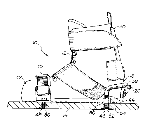
FIqU~E 1 is a ~ide elevation view of a boot binding system
of a snowboard constructed in accordance with the teachings of
the present invention.
FIGURE 2 is a rear elevation view of the boot binding
~ystem illustrated in FI~UR~ 1.

20~9~1~
.
FIGURE 3 is a side elevation view in longitudinal section
of the boot binding system in FIGURE 1.
FIGURE 4 is an exploded perspective view of components of
the boot binding system illustrated in FIGURE 1.
s
ETAILED DESCRIPTION OF THE PREFERRED EMBODIMENT
The preferred embodiment, a boot binding system for a snow
board generally identified by reference numeral 10, will now
be described with reference to FIGURES 1 through 4.
Boot binding system 10 is intended to securely position
a boot 12 onto a snowboard 14. Referring to FIG~RES 2 and 4,
boot binding system 10 includes a rigid heel support 16. ~eel
support 16 i8 adapted for attachment to a heel 18 of boot 12.
Heel support 16 has an attached protruding member 20 with a
channel 22. Referring to FIGUR~ 3, heel ~upport 16 i3 secured
heel 18 of boot 12 and to protruding member 20 by means of
20 bolts 24 and nuts 26~ A rigid ankle support 28 is adapted for
insertion in an elongate pocket 30 positioned along a rear seam
32 of boot 12r Ankle ~upport 28 is pivotally secured to heel
support 16 by means of nut 34 and bolt 36. Referrin~ to
FIGURES 1 and 2, a heel binding ie provided which consists of
a generally "U" shaped overlay member 38 which wraps around
heel 18 of boot 12 and overlay~ protruding member 20 engaging
channel 22. A toe binding is provided consisting of an
attachment strap 40 adapted to se~ure a toe 42 of boot 12 to
snowboard 14. Generally "U" shaped overlay member 38 has
threaded end portions 44. Snowboard 14 has threaded aperture~
46 and 480 A coupling member 50 i~ used to attach generally
"U" shaped overlay member 38 to snowboard 14. Coupling member
50 ha~ a bolt-like male end 52 and a nut-like female end 54.
Male end 52 is insertable into threaded apertures 46. Female
end 54 receive~ threaded end portions 44 of generally "U"
shaped overlay members 38. Coupling member 50 has threads cut
in opposing directione such that as coupling member 50 is

2089313
rotated coupling member 50 is dxawn into apertures 46 in
snowboard 14 while concurrently threaded end portion 44 of
generally "U" shaped overlay member 38 is drawn into female end
54 of coupling member 50. Attachment strap 40 i5 attached to
apertures 48 in snowboard 14 by means of bolts 56.
The use and operation of boot binding system 10 will now
be described with reference to FIGURES 1 through 4. Boot
binding system 10 is comparatively easy to get in and out of.
This is significant in that a snowboarders means of propulsion
on a level surface is to get one leg free and push with the
free foot in the manner of a skateboard. The cnowboarder
merely inæerts protruding me~ber 20 under generally "U" shaped
overlay member 38. Generally "U" shaped overlay member 38
wraps around heel 18 of boot 12 and overlays protruding member
20 engaging channel 22. Once overlay member 38 is engaged in
channel 22 heel 18 of boot 12 cannot be raised. Attachment
strap 40 is then fastened down over toe 42 of boot 12, this
secures toe 42 of boot 12 to snowboard 14 and prevents
ZO protruding member 20 from being moved relative to overlay
member 38. In re~ponse to movement of the snowboarder ankle
support 28 pivots laterally and flexes forwardly. However, if
the snowboarder leans rearwardly, ankle support 28 provides
needed rigid æupport rearwardly. Once on a level surface, the
snowboarder merely unbuckleæ attachment strap 40, raises his
toes to diæengage overlay member 38 from channel 22 and slides
his foot forward to remove protruding member 20 from overlay
member 38.
It will be apparent to one skilled in the art that boot
binding system 10 provides a degree of flexibility needed to
perform trick maneuvers while provided sufficient support to
enable the snowboarder to maintain his balance. It will also
be apparent to one skilled in the art that modifications may
be made to the illustrated e~bodiment without departing from
the spirit and ~cope of the invention as defined by the Claims.
,,, . ,. , . , . ` c ~.. ! . ' ~ ~

Representative Drawing
A single figure which represents the drawing illustrating the invention.
Administrative Status

2024-08-01:As part of the Next Generation Patents (NGP) transition, the Canadian Patents Database (CPD) now contains a more detailed Event History, which replicates the Event Log of our new back-office solution.

Please note that "Inactive:" events refers to events no longer in use in our new back-office solution.

For a clearer understanding of the status of the application/patent presented on this page, the site Disclaimer , as well as the definitions for Patent , Event History , Maintenance Fee  and Payment History  should be consulted.

Event History

Description Date
Inactive: IPC deactivated 2012-01-07
Inactive: IPC expired 2012-01-01
Inactive: IPC from PCS 2012-01-01
Inactive: First IPC from PCS 2012-01-01
Inactive: IPC from PCS 2012-01-01
Inactive: IPC from MCD 2006-03-11
Time Limit for Reversal Expired 1999-02-11
Application Not Reinstated by Deadline 1999-02-11
Deemed Abandoned - Failure to Respond to Maintenance Fee Notice 1998-02-11
Application Published (Open to Public Inspection) 1994-08-12

Abandonment History

Abandonment Date Reason Reinstatement Date
1998-02-11
Owners on Record

Note: Records showing the ownership history in alphabetical order.

Current Owners on Record
RANDY JESPERSEN
Past Owners on Record
None
Past Owners that do not appear in the "Owners on Record" listing will appear in other documentation within the application.
Documents

To view selected files, please enter reCAPTCHA code :


To view images, click a link in the Document Description column. To download the documents, select one or more checkboxes in the first column and then click the "Download Selected in PDF format (Zip Archive)" or the "Download Selected as Single PDF" button.

List of published and non-published patent-specific documents on the CPD .

If you have any difficulty accessing content, you can call the Client Service Centre at 1-866-997-1936 or send them an e-mail at CIPO Client Service Centre.


Document
Description 
Date
(yyyy-mm-dd) 
Number of pages   Size of Image (KB) 
Drawings 1994-08-11 4 188
Claims 1994-08-11 3 175
Abstract 1994-08-11 1 73
Descriptions 1994-08-11 4 294
Representative drawing 1998-08-04 1 22
Courtesy - Abandonment Letter (Maintenance Fee) 1998-03-10 1 187
Fees 1997-01-29 1 55
Fees 1996-02-07 1 57
Fees 1995-01-23 1 52