Note: Descriptions are shown in the official language in which they were submitted.
D-92-1-005 -1- PATENT APPLICATION
ARC DISCHARGE L~MP CONTAINING MECHANISM FOR
EXTINGUISHING ARC AT END-OF-LIF~
CROSS-REFERENCE TO RELATED
APPLICATIONS
This application, which discloses and claims
structural features for a low-pressure arc discharge
lamp, relates to subject matter disclosed and
claimed in the following copending applications,
which are assigned to the assiqnee of the present
application and are hereby incorporated by reference:
U.S. Serial No. (Attorney Docket No. D-91-1-901~
of Thomas Haraden et al filed concurrently herewith
and entitled "ARC DISCHARGE LAMP HAVING CEMENTLESS
BASE MEMBERS",
U.S. Serial No. 07/547,942 of Ronald G.
~I Blaisdell et al filed July 3, 1990 and entitled
\~ "METHOD AND APPARATUS FOR FORMING APERTURES IN
FLUORESCENT LAMPS", and
U.S. Serial No. 07/547,984 of Ronald G.
81aisdell et al filed July 3, 1990 and entitled
"APERTURE FLUORESCENT LAMP ~ITH PRESS SEAL
CONFIGURATION".
208931~
D-92-1-005 -2- PATENT APPLICATION
FIELD OF THE INVENTION
This invention relates to the field of
low-pressure arc discharge lamps. More
particularly, the invention relates to low-pressure
arc discharge lamps, such as subminiature
fluorescent lamps, having a structure or device
which renders the lamp inoperable at the end of its
useful life.
BACKGROUND OF THE INVENTION
Herein, the terms "end-of-life" and "end of the
useful life" of a low-pressure arc discharge lamp
are defined as that time when the electron-emissive
material on one electrode filament has been depleted
causing the arc discharge to destroy the filament
and/or strike other parts of the electrode mount
structure.
Low-pressure arc discharge lamps, such as
fluorescent lamps, are well known in the art and
typically include a pair of electrodes made of a
coil of tungsten wire upon which is deposited a
coating of an electron-emissive material consisting
of alkaline metal oxides (BaO, CaO, SrO) to lower
the work function of the cathode and thus improve
lamp ~fficiency. With electron-emissive material
disposed on the electrode filament, the cathode fall
voltage is typically about 13 volts. However, at
the end of the useful life of the lamp when the
2~89314
D-92-1-005 -3- PATENT APPLICATION
electron-emissive material on one of the electrode
filaments becomes depleted, the cathode fall voltage
rises by 100 volts or more. If the external
circuitry fails to limit the open circuit voltage
across the lamp, the lamp may continue to operate
with the additional power being deposited at the
lamp electrode region. By way of example, a lamp
which normally operates at 0.1 amp would deposit
0.65 watt at each electrode during normal
operation. At end-of-life, the depleted electrode
may consume 7.5 watts due to the increase in cathode
fall voltage. This extra power can lead to
excessive local heating of the lamp and fixture.
Low-pressure arc discharge lamps, especially
those designed for operation at high current (1.5
amp) loading, such as very high output (VHO) lamps,
sometimes fail by causing the fracture of the glass
envelope. It is believed the sequence of events
leading to such failures is as follows. At the end
of the useful life of the lamp, the
electron-emissive material on one of the electrode
filaments becomes depleted. When such depletion
occurs, the arc discharge strikes other components
of the electrode structure and, in particular, the
arc strikes the electrical leads supporting the
electrode structure. The electrical leads are
heated by the arc to the point where the wires
soften and bend~ Subsequently, the electrical leads
and the electrode structure sag and come in contact
with the glass envelope. The severe heat generated
2089314
D-92-1-005 -4- PATENT APPLICATION
by the arc and the heated electrode structure cause
the glass envelope to fracture.
Various internal structures for low-pressure arc
discharqe lamps have been proposed which cause the
lamp to fail without fracture of the glass
envelope. Such structures are suggested in the
following references.
U.S. Patent No. 3,265,917, which issued to Ray
on August 9, 1966, discloses a structure comprising
a wire or conductive coating electrically connected
to the inside portion of the electrode structure and
extending to a thin-walled portion of the glass stem
press. Upon depletion of the electron-emissive
material on the electrode filament, the arc strikes
and follows the conductive path reaching the
thin-walled portion of the stem press. The heat
generated by the arc and the heated conductor
softens and melts the thin wall of the stem press to
the point where the hermetic seal i8 lost. The
introduction of the external atmosphere into the
lamp extinguishes the arc discharge and renders the
lamp inoperable.
U.S. Patent No. 4,105,910, which issued to Evans
on August ~, 1978, discloses a structure providing
for an auxiliary source of amalgam and for
end-of-life extinguishment of the arc. This
structure comprises a coating of a suitable
amalgamative metal on portions of the stem press and
the inside lead-in wire a~out the point where the
lead-in wire emerges from the stem press.
- 2089314
D-92-1-005 -5- PATENT APPLICATION
U.S. Patent No. 4,495,440, which issued to
Schlitt et al, discloses an arc-extinguishing ampul
mounted on each electrode structure. The ampul
comprises a thin-walled glass body enclosing an
arc-extinguishing gas, at least one electrically
conductive support wire, and a heat-conductive
coating covering the outer surface of the ampul and
portions of the support wire. Upon depletion of the
electron-emissive coating on one electrode filament
at the end of the useful life of the lamp, the arc
discharge is attracted to the ampul by the support
wire. The heat of the arc softens and melts the
ampul to the point where the arc-extinguishing gas
within the ampul escapes and renders the lamp
inoperable without loss of the lamp's hermetic seal.
Although the above-described end-of-life
structures have been employed with varying degrees
of success, it has been found that certain
disadvantages do exist and such structures do leave
something to be desired. More specifically, the
above-described wire, conductive coating or
amalgamative metal require a stem press mount
configuration to implement. On the other hand, the
ar~-extinguishing ampul is rather expensive from a
lamp-manufacturing standpoint because it adds
additional manufacturing steps to the lamp process.
Therefors, it would be very desirable and
advantageous to have an end-of-life structure that
does not require a stem press mount and which is
more economical to utilize.
2089314
D-92-1-005 -6- PATENT APPLICATION
SUMMARY OF THE INVENTION
It is, therefore, an object of the present
invention to obviate the disadvantages of the prior
art.
It is another object of the invention to provide
an improved arc discharge lamp.
It is a further object of the invention to
provide an arc discharge lamp containing an
end-of-life structure which does not require the
lamp to have a stem press mount.
It is yet another object of the invention to
provide an improved end-of-life structure which is
sconomical and does not add additional manufacturing
steps to the lamp process.
The~e o~jects are accomplished in one aspect of
the invention by the provision of an arc discharge
lamp comprising a light-transmissive envelope having
a tubular-shaped main body and a press seal disposed
at each end of the main body. The main body of the
envelope has an internal diameter and contains a
fill material for supporting a low pressure
discharge. A layer of phosphor is disposed on a
surface within the main body of the envelope. An
electrode filament including a pair of electrode
filament ends is located in each end of the main
body. Each electrode filament end is in a
contiguous relationship with an inside surface of
the envelope. The arc discharge lamp further
208931~
~-92-1-005 -7- PATENT APPLICATION
includes a pair of electrical leads attached to each
electrode filament and sealed within a respective
press seal.
In accordance with further teachings of the
present invention, each electrode filament has an
axial length greater than the internal diameter of
the envelope. In one embodiment, the axial length
of the electrode filament is equal to about 7 mm and
the internal diameter of the envelope is equal to
about S mm. Preferably, each pair of electrical
leads includes a glass bead formed thereon for
maintaining separation of said said electrical leads.
In accordance with further aspects of the
present invention, the arc discharge lamp further
includes an insulative base member disposed at each
end of the lamp. Each of the base members surrounds
a respective press seal and a portion of the
tubular-shaped main body of the envelope.
Preferably, the base member extends axially from the
press seal and beyond the center of a respective
electrode filament.
Additional objects, advantages and novel
features of the invention will be set forth in the
description which follows, and in part will become
apparent to those skilled in the art upon
examination of the following or may be learned by
practice of the invention. The aforementioned
objects and advantages of the invention may be
realized and attained by means of the
instrumentalities and combination particularly
pointed out in the appended claims.
20~9314
D-92-1-005 -8- PATENT APPLICATION
BRIEF DESCRIPTION OF THE DRAWINGS
The nvention will become more readily apparent
from the following exemplary description in
connection with the accompanying drawings, wherein:
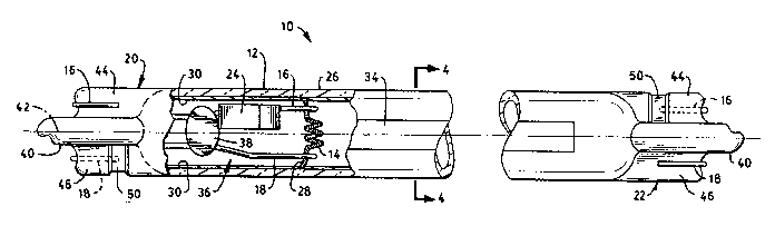
FIG. 1 is a plan view, partially in cross
section, of one embodiment of an arc discharge lamp
in accordance with the present invention;
FIG. 2 is a partial view, partially in cross
section, of the arc discharge lamp of FIG. 1 showing
one of the press seals;
FIG. 3 is an end view of the fluorescent lamp of
FIG. l;
FIG. 4 is a cross-sectional view of the
fluorescent lamp of FIG. 1 taken along the lines
4--4 of FIG. 1:
FIG. 5 is a plan view of a mount structure for
use in the arc discharge lamp of FIG. l;
FIG. 6 is a plan view, partially in cross
section, of another embodiment of an arc discharge
lamp in accordance with the present invention;
FIG. 7 is an end view of the arc discharge lamp
of FIG. 6;
20893~4
D-92-1-005 -9- PATEN~ APPLICATION
FIG. 8 is a partial view of the arc discharge
lamp of FIG. 6 showing one of the lamp base members
surrounding one of the press seals and a portion of
the main body of the lamp: and
FIG. 9 is a cross-sectional view of the
fluorescent lamp taken along the lines 9--9 in FIG.
8.
BEST MODE FOR CARRYING OUT THE INVENTION
For a better understanding of the present
- invention, together with other and further objects,
advantages and capabilities thereof, reference is
made to the following disclosure and appended claims
in connection with the above-described drawings.
With particular attention to FIGS. 1-4, there is
illustrated an improved low-pressure arc discharge
lamp 10 (i.e., a fluorescent lamp) in accordance
with the teachings of the invention. Lamp lO
generally includes a tubular-shaped
light-transmissive envelope 12 having a
tubular-shaped main body. Envelope 12 is typically
fabricated of soda lime glass and, by the way of
example, can have an outside diameter on the order
of about 0.18 inch to 0.27 inch and a length in the
range of 4-20 inches. An electrode filament 14 is
mounted in each end of envelope 12. Electrical
leads 16 and 18 are connected to filament 14 and
208931~
D-92-1-005 -10- PATENT APPLICATION
extend through a press seal 20. A glass bead 38
formed on electrical leads 16 and 1~ insures that a
predetermined separation between the electrical
leads is maintained during formation of the press
seal. The opposite end of the lamp 10 is
constructed in the same manner and includes a press
seal 22. A mercury dispenser 24 at one end of the
lamp is attached to electrical lead 16. The lamp 10
contains a fill material including mercury supplied
from dispenser 24 and a rare gas such as argon at a
low pressure (e.g., 5 torr).
As illustrated in FIGS. 1 and ~, a coating 30 is
applied to the inside surface of envelope 12. Lamp
10 may include an aperture 34 which is formed in
layer 30 to direct light from lamp 10 in a preferred
direction. As best shown in FIG. 1, the aperture 34
extends axially along a major portion of length of
envelope 12 and has a uniform width. The width of
aperture 34 depends on the desired radiation pattern
from lamp 10. In the case of an aperture
fluorescent lamp, layer 30 comprises a reflective
layer and a phosphor layer. The reflective layer is
first applied to the inside surface of envelope 12
and then the phosphor layer is applied sver the
reflective layer. The reflective layer has a
reflective inside surface. The reflective layer
insures that light emitted fro~ the lamp 10 is
directed through aperture 34. In an alternative
configuration, the reflective layer is removed in
aperture 34 but a phosphor layer is applied to the
entire inner surface of envelope 12.
2089314
D-92-1-005 -11- PATENT APPLICATION
In another alternative, aperture 34 and the
reflective layer are omitted. In this case, the
phosphor layer is uniformly applied to the inside
surface of envelope 12, and the lamp provides a
uniform cylindrical radiation pattern.
A preferred technique for scraping aperture 34
is described in detail in copending application
Serial No. 07/547,942 filed July 3, 1990 and
assigned to the assignee of the present application.
The press seals 20 and 22 each include a
tubulation 40 generally positioned on an axis 42 of
envelope 12 and flattened regions 44 and 46 on
opposite sides of tubulation 40. Electrical lead 16
extends through and is sealed into flattened region
44, and electrical lead 18 extends through and is
sealed into flattened region 46. Flattened regions
44 and 46 include generally flat surfaces 44a and
46a (FIG. 3), respectively, which are u~ed for
orientation of aperture 34~ In a preferred
embodiment, the surfaces 44a and 46a are oriented at
90- with respect to a line drawn through the center
of aperture 34 and the axis 42 of the envelope 12.
Electrical leads 16 and 18 extend from the end
of press seal 20 for connection of the electrode
filament 14 to a source of electrical energy. In
one configuration as shown, electrical leads 16 and
18 are bent on opposite sides of press seal 20 and
extend along the surfaces of flattened regions 44
and 46 respectively. In another configuration, the
leads 16 and 18 extend from the end of lamp 10
20~9314
D-92-1-005 -12- PATENT APPLICATION
parallel to axis 42 and can be connected to leads
from the electrical source in any convenient manner,
such as by crimping.
The press seals 20 and 22 can be provided with
means for positioning the baseless lamp 10 of FIG. 1
along axis 42. The positioning means can comprise
one or more detents 50 formed in the press seals 20
and 22. In the example shown in FIGS. 1 and 2, the
detents 50 comprise a depression or groove in
flattened regions 44 and 46. The groove is oriented
with its sides perpendicular to the axis 42 of
envelope 12. Thus, when detent 50 engages a
projection in the lamp mounting hardware (not
shown~, the lamp 10 is prevented from moving along
axis 42. In a preferred embodiment, one detent 50
is provided on each side of each press seal. Thus,
with respect to press seal 20, a detent 50 is
located on the front of flattened region 46 and a
detent (not shown) is located on the back of
flattened region 44. Alternatively, the detents 50
can be replaced with projections which engage
corresponding detents in the mounting hardware.
That portion of each electrode filament 14
located between electrical leads 16 and 18 is coated
with a quantity of electron-emissive material in
order to lower the work function of the cathode and
thus improve lamp efficiency. As stated earlier, at
the end of the useful life of the lamp, the
electron-emissive material on one of the electrode
filaments becomes depleted causing the cathode fall
208931 4
D-92-1-OOS -13- PATENT APPLICATION
voltage to rise by 100 volts or more. If the
external circuitry fails to limit the open circuit
voltage across the lamp, the lamp may continue to
operate with the additional power being deposited at
the lamp cathode region. This extra power can lead
to excessive local heating of the lamp and fixture.
In accordance with the teachings of the
invention, each electrode filament 14 is provided
with a pair of ends 26 and 28 (FIG. 1), which extend
toward and are in a contiguous relationship with an
inside surface of the main body of envelope 12.
During normal operation, the heating of electrode
lS filament 14 is confined to those regions of the
electrode filament located between electrical leads
16 and 18. Accordingly, little heat is conducted to
the glass wall and operation of lamp 10 is
unaffected.
It has been discovered that at end-of-life, the
heating of an electrode filament depleted of
electron-emissive material increases by up to a
factor of ten and extends uniformly to the coil ends
beyond electrical leads 16 and 18. As a result, a
localized hot spot is produced on the glass wall
where the electrode filament end touches. This
localized heating causes a puncture in the la~p
envelope and evacuation of the lamp. The
introduction of the external atmosphere into the
lamp extinguisheæ the arc discharge and renders the
lamp inoperable.
~0~931~
D-92-1-005 -14- PATENT APPLICATION
FIG. 5 illustrates a mount 36 used in
fabricating lamp 10. Mount 36 includes filament 14
supported by electrical leads 16 and 18 which are
maintained separated by a conventionally-known glass
bead 38. A mercury dispenser 24 is shown secured to
electrical lead 16. It is understood that if a
dispenser is employed as a means of introducing
mercury into the lamp, only one dispenser is
required per lamp.
In order to insure that ends 26 and 28 of
electrode filament 14 firmly contact the inside
surface of envelope 12, the axial length Dl (FIG. s)
of electrode filament 14 is slightly greater than
the internal diameter of envelope 12. In a typical
example, a subminiature fluorescent lamp having an
envelope with an internal diameter of about 5 mm,
would typically have a length Dl equal to about 7 mm.
The creation of a puncture in the lamp envelope
may, in some instances, xesult in fracture of the
lamp envelope and loss of structural integrity.
Referring next to FIGS. 6-8, there is shown an arc
discharge lamp 10' according to another embodiment
of the present invention, wherein similar
constituent members as those in FIG. 1 are denoted
by the same reference numerals. Lamp 10' includes
an electrically insulating (e.q., plastic) base
member 60 secured to each end of the lamp.
20893~ ~
D-92-1-005 -15- PATENT APPLICATION
Base member 60 is of unitary construction and
includes a first portion 62 having a tubular outer
shape and a second portion 64 having a flattened
shape and protruding from first portion 62. As
shown in FIG. 7, a pair of apertures 66 are located
within flattened portion 64, each of which extends
through flattened portion 64 and is designed for
having a respective exteriorly projecting portion of
an electrical lead 16, 18 pass therethrough. As
further illustrated in FIG. 7, a groove 76 is formed
in the terminal end of flattened portion 64 for each
electrical lead 16, 18. Grooves 76 provide
positioning and allow the electrical leads to be
flush with the end of the base member.
One end 84 of first base member portion 62
located adjacent flattened portion 64 defines
therein an opening 68 (FIG. 9) which is designed for
having press seal 20 securedly positioned therein.
As shown in FIG. 6, the other end 86 of first
portion 62 of the base member defines therein a
circular opening 88. End 86 iB designed to surround
that portion of the lamp envelope ad;acent electrode
mount structure 36 and, preferably, to extend along
the lamp axis and beyond the center of electrode
filament 14 by a length D2 (FIG. 6). Typically,
distance D2 is equal to about 3/16 inch ~4.75 mm).
Extending the first base member portion 62 provides
support to the lamp envelope in the event that the
envelope cracks in the area immediately adjacent the
electrode filament ends ~6 and 28.
2089314
D-92-1-005 -16- PATENT APPLICATION
To assist in retaining the base member on arc
discharge lamp 10', at least one protruding segment
82 (as illustrated in FIGS. 8 and 9), projects from
an internal wall of first base member portion 62.
Preferably two such segments are utilized and
positioned in a diagonally-opposing relationship as
best illustrated in FIG. 9. Each of these
protruding segments is designed for being aligned
with and subsequently located within a corresponding
detent 50 of press seal 20, 22. When one of the
press seals of lamp 10' is inserted within a
respective base member 60, each of the protruding
segments 82 is inserted within a corresponding
detent 50, the result being that the press seal is
substantially "locked" in position.
To assure positive positioning therein without
causing damage to the press seal, the first portion
62 of base mem~er 60 further includes flexure means
70 therein as illustrated in FIGS. 8 and 9 to enable
this part of the base member to expand a
predetermined amount during said positioning.
Flexure means 70 is preferably in the form of two
elongated slots 72 formed within first portion 62 to
thus enable the first portion to expand outwardly
during positioning of the press seal within the base
member. The press seal is thus firmly positioned
within base member 60 without the need for cement or
the like.
2089314
D-92-1-005 -17- PATENT APPLICATION
To maintain the externally projecting portions
of electrical leads 16, 18 in proper alignment, base
member 60 further includes a plurality of channels
74 (FIGS. 6-8), each located on first portion 62 of
the base member adjacent flattened portion 64. Each
channel 74 is designed to have one of the terminal
ends of a respective electrical lead 16, 18 inserted
therein.
As depicted in FIG. 7, each ~hannel 74 includes
a tapered portion 80 which facilitates positioning
of the substantially annular (round) electrical
leads therein. In addition, each channel further
includes a narrowed portion formed by a pair of
opposing bumps 78 separated a distance which is
slightly smaller than the diameter of the electrical
lead. Once the terminal end of the electrical lead
is forced past bumps 78, the electrical lead is
retained and prevented from springing back. In
addition to retaining the terminal ends of the
electrical leads, bumps 78 provide a reservoir of
material which can be mechanically pushed towards
the resting electrical lead to more positively
retain the electrical lead.
As a result of channels 74, each of the terminal
ends of the electrical leads i8 secured to the base
member in a locking relationship to thus prevent
subsequent removal thereof during the positioning cf
each lamp end within a corresponding socket member
(not ehown). Such retention also serves to assist
in maintaining the press seal of lamp 10' firmly
2089314
D-92-1-005 -18- PATENT APPLICATION
within base member 60. A total of two channels are
provided on each base member, one for each of the
mentioned electrical leads.
There has thus been shown and described an
improved arc discharge lamp. The arc discharge lamp
contains an end-of-life structure which does not
require the lamp to have a stem press mount. The
end-of-life structure is economical and does not add
additional manufacturing steps to the lamp process.
While there have been shown and described what
are at present considered the preferred embodiments
of the present invention, it will be obvious to
those skilled in the art that various changes and
modifications may be made therein without departing
from the scope of the invention as defined by the
appended claims.