Note: Descriptions are shown in the official language in which they were submitted.
PROCESS FOR PRODUCING PLATE-SHAPED BODIES MADE OF A
MIXTURE OF PLASTER AND FIBROUS MATERIALS AND
INSTALLATION FOR IMPLEMENTING
FIELD OF THE INVENTION
The invention relates to a process for pro-
ducing plate-shaped bodies from a mixture of plaster
and fibrous materials, comprising the following pro-
cess steps:
a) preparing a wet mixture of plaster and
0 fibers;
b) spreading the mixture to form a mat;
c) compressing the mat into a raw plate; and
d) setting and drying the raw plate.
In addition, the invention relates also to
5 an installation fsr implementing the process with:
a) a device preparing a wet mixture of plaster
and fibrous materials;
b) a spreading device spreading the wet mixture
onto a molding line to form a mat;
c) a press through which the mat lying on the
molding line is passed in order to be compressed into
a raw plate;
d) a setting station wherein the plaster in the
raw platee sets; and
e) a drying stati~n wherein the set raw plates
are dehumidified,
'''
BAC~ROUND OF THE INVENTION
A process and an installation of this kind
are described in DE-OS 38 01 315. This publication
descr~bes the problems encountered when trying to set
the water content of the wet plaster-fiber mixture and
the possible solutions which have already been found.
In the process described in DE-OS 38 01 315 the
wetting of the mixture is carried out in two steps. A
first portion of the required water is mixed into the
dry mixture; the still spreadable mixture is then
molded to a mat in several layers, similar to the
process of producing pressed particle boards. The
balance of the required water is then sprayed onto the
individual layers of the spread mixture. The mat pro-
duced this way is then compressed into a raw plate in
a press. The strength of the plates produced this way
is very good, however it has been found that further
improvement is possible.
OBJECT OF THE INVENTION
It is the object of the present invention to
provide an improved process and apparatus for pro-
ducing plate-shaped bodies with higher strength in a
simple manner.
SUMMARY OF THE INVENTION
This object ie obtained in the process of
the invention in that between the process steps c and
d the following further process steps take place:
e) subsequent wetting of the top and bottom
faces of the raw plate; and
f) subsequent compression of the subsequently
wetted raw plates with a maximum pressure not
exceeding the pressure used in process step c.
The process of the invention is based on the
fact that a prewetted mixture after the first com-
pression step at the highest pressure used in the
total process is mechanically so stable that it is
self-supporting. It is possible to further wet the
bottom face. The subdivision of the total compression
into two steps has various advantages:
The compression process, which always also
removes the air from the mat, is thus separated from
the surface formation of the raw plate.
For the production efficiency of an instal-
lation it is always of particular importance that the
air locked in the mat be expelled quickly and com-
pletely during compression. In practice this is
achieved by using vent screens which are inserted
between the press surfaces and the mat surface. As a
result the pattern of the screens imprints itself on
the surface of the raw plates and the imprint has to
be subsequently removed by grinding, at least on one
face. In the process of the invention it is possible
to operate in the second compression step with a
smooth press surface, instead of the screen. The
', , :',
, ', ' ' , ',, ' ' ,,, ' '
,
- 4 -
water enrichment in the surface area of the raw plates
causes a certain plasticity, so that the screen
pattern can be substantially flattened during com-
pression.
A further advantage of the process of the
invention:
In the state of the art the plate-shaped
body cannot be directly covered with a coating during
its formation, because of the necessity to remove the
air. However, in the second step of the process
according to the invention, when air no longer has to
be removed, it is possible to apply a coating. It is
only necessary to be certain that the plate-shaped
body will still be able to dry out.
Advantageously the top and bottom faces of
the raw plate are each subsequently wetted with 200 to
1000 g/m2 of water~ In process step (a) the humidity
i8 preferably set at 22 to 28% water in relation to
the dry mixture and the compression pressure in pro-
cess step (f) ranges between 0.5 and 2 MPa.
The compression time in process step (c) can
range between 10 and 20 sec. The water amount absorb-
ed by the bottom face of the raw plate can be deter-
mined and the water amount fed to the top face of the
raw plate can be established according thereto. Pre-
ferably the water amounts absorbed by the top face and
the bottom face of the raw plate are equal.
The water amount absorbed at the top face o~
the raw plate, when considered with re~pect to the
total mass of the raw plate, can be approximately 1 to
4% higher than the water amount absorbed at the bottom
face of the raw plate. The bottom face of the raw
plate can be subsequently wetted by spraying, while
the raw plate is kept freely suspended.
Advantageously the wetting of the bottom
face of the raw plate takes place while the raw plate
is guided over a splash bath. Alternatively the sub-
sequent wetting of the raw plate takes place through
roller application.
The compression pressure in process step (f)
can equal 50 to 100% of the compression pressure in
process step (c). The compression time in process
step (f) can range between 5 and 30 sec. and in pro-
cess step (f) a periodically alternating compression
pressure can be exerted.
The above-mentioned object is attained
regarding the installation in that between the press
and the setting station the following are interposed:
f) an aftertreatment station, wherein the top
and bottom faces of the raw plates are subsequently
wetted; and
g) a second press wherein the subsequently
treated raw plates are subsequently compressed.
The advantages of the installation according
' ~' " ' ~ '';
, ... . . . .
,, " , , ~ , , ' ' , "
' ' ', ' , ' ,' ':, ~ :
,
to the invention correspond respectively with the
already explained advantages of the process of ~he
invention.
According to a feature of the invention, the
subsequent wetting station for the bottom face of the
raw plate comprises a lifting device capable to
maintain and transport the raw plate freely suspended,
as well as a multitude of nozzle through which the
bottom face of the raw plate held by the lifting
device can be sprayed. In each branch pipe leading to
a nozzle a solenoid valve can be provided. The subse-
quent wetting station for the bottom face of the raw
plate can comprise a multitude of containers which can
be supplied with water and whose upper side provided
with at least one passage opening is arranged immedi-
ately below the travel path of the raw plate. In each
of the branch pipes leading to a container a solenoid
valve can be provided which admits or stops the access
of the water to the container. Each solenoid valve
can be a three-way valve and in one of the positions
opens the path from the inner space of the pertaining
container to a drainage tank. The inner space of each
container can be connected to an air blower. In each
branch pipe leading from a container to the air blower
a closable flap can be provided.
According to another feature at least one
collecting tank is provided, wherein the excess water
not absorbed by the bottom face of he raw plate is
collected and from which the excess water flows into
the measuring tank of a differential balance.
The subsequent wetting station for the
bottom face of the raw plate can comprise an endlessly
running, flat and absorptive material which runs
through a water supply in a vat and which in a certain
segment of its path is pressed against the bottom face
of the raw plate which is travelling by. A pipe can
be provided through which the vat is supplied with
fresh water as well as an overflow through which the
excess water flows from the vat into the measuring
tank of a differential balance. An endless screen
belt can hold and transport the raw plate in the
subsequent wetting station for the bottom face of the
raw plate. A roller can partially dip into the water
supply in the vat and can be wrapped by the flat
material. A pressure roller presses the flat material
against the roller at the location where after passing
through the water supply it leaves the roller, whereby
the contact pressure of the pressure roller is adjust-
able. - -
The subsequent wetting station for the top
face of the raw plate can comprise a multitude of
25 nozzles through which the top side of the raw plate --
lying on a conveyor belt can be sprayed. In each
branch pipe leading to a nozzle a solenoid valve can
,
be provided.
Furthermore the subsequent wetting station
for the top face of the raw plate is built analogously
to the aftertreatment station for the bottom face of
the raw plate.
The apparatus can comprise a control device
which comprises a measured-value indicator (39, 239)
for the water amounts absorbed by the bottom face of
the raw plate and a measured-value indicator (42, 242)
for the water amounts absorbed by the top face of the
raw plate and keeps the two water amounts in a certain
proportion with respect to each other by subsequent
adjustment of the water amounts supplied to the top
face of the raw plate. The measured-value indicator
~139, 239) for the water amounts absorbed at the
bottom face of the raw plate can be a differential
gauge receiving the following:
The exit signal of a flowmeter (38, 138,
238) measuring the water amount supplied to the bottom
face of the raw plate; and
the exit signal of a differential balance
(29, 129, 229) whose measuring tank (28, 128, 228)
collects the return flow of excess water coming from
the bottom face of the raw plate.
The measured-value indicator for the water
amount absorbed at the top face of the raw plate can
be flowmeter measuring the water amounts supplied to
the top face of the raw plate. According to a further
feature, the second press is a flat press, a roller
press wherein a periodically alternating pressure is
exerted on the raw plate, a smooth, entrained press
plate, or a structured press plate.
BRIEF DESCRIPTION OF THE DRAWING
The above and other objects, features, and
advantages will become more readily apparent from the
following, reference being made to the accompanying
drawing in which:
Figure 1 is a section of an installation for
producing plate-shaped bodies from a mixture of
plaster and fibrous materials;
Figure 2 is a section through the subsequent
wetting station of the installation in Figure 1 on a
larger scale;
Figure 3 is a longitudinal section through a
second embodiment of an installation for producing
plate-shaped bodies;
Figure 4 is a section through the subsequent
wetting station of the installation of Figure 3 on a
larger scale;
Figure 5 is a longitudinal section through a
third embodiment of an installation for producing
plate-shaped bodies; and
Figure 6 is a sectional view of a subsequent
wetting station of the installation in Figure 5 on a
-- 10 --
larger scale.
SPECIFIC DESCRIPTION
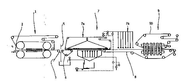
In Figure 1 the reference numeral 1 marks a
continuously running band press which operates corre-
spondingly to the band press 46 of the already men-
tioned DE-OS 38 01 315. In order to more fully de-
scribe the process respectively installation segments
preceding the band press 1 reference is made to this
publication and especially to its Figure 1 and thereto
pertaining description. In this connection it suf-
fices to know that on a moving molding face 2, which
comprises an endless molding belt 3 moving through the
band press 1, mats consisting of a still loose mixture
of plaster and fibers are fed in the direction of
arrow 4, The wetness ranges between 20 and 33% water,
referred to the dry mixture. The mat is compressed in
the band press l during a compression time between 10
and 20 s under a pressure of 1 to 2 MPa and finished
at the edges into the following cutting device 5.
The raw plate is introduced in the subse-
quent wetting station bearing the general reference
numeral 7 by a short transfer belt 6. Details of the
subsequent wetting station 7 are described further
below with the aid of Figure 2. Now it suffices to
know that the subsequent wetting station 7 is subdi-
vided into a subsequent wetting station 7A wherein the
botto~ side of the raw plate is wetted and a subse-
quent wetting station 7B wherein the top side o~ theraw plate is wetted.
On a conveyor belt 8 the raw plate addition-
ally wetted on its top and bottom faces reaches a con-
tinuously running roller press 9, wherein a furthersubsequent compression takes place, whereby it is
self-understood that the plaster contained in the mass
is also not fully set. In the roller press 9 an end-
less, smooth press belt so is entrained, so that a
smooth surface of the raw plate results. It is help-
ful that the surfaces of the not yet fully set raw
plates still maintain a certain plasticity after the
wetting in station 7. The compression pressure in the
roller press 9 ranges between 50 and 100% of the com-
pression pressure in band press 1, but is not higherthan the latter. Due to the construction of the
roller press 9 the compression pressure alternates
periodically.
Instead of roller press 9 it is also possi-
ble to use face presses, whereby the compression time
would range between 5 and 10 seconds.
If a structured surface of the raw plate is
desired, it is possible to fit a structured com-
pression plate in the roller press 9.
The roller press 9 wherein the subsequent
compression of the subsequently wetted raw plates
takes place is followed by the usual installation
,, ",
- 12 -
sections, as known for instance from DE-OS 38 01 315
This means especially that a setting and drying
stretch is provided. However these are not shown in
the drawing.
The details of the subsequent wetting
station 7 can be better seen in Figure 2 than from
Figure 1. The raw plate fed on the short conveyor
belt 6 from the left in Figure 2 is transferred to a
lifting device 10 which is part of the subsequent
wetting station 7A for the bottom side. The lifting
device 10 comprises a funnel-shaped vacuum chamber 11
whose inner space is evacuated by a vacuum pump 12.
The lower, flat frontal surface 13 is provided with a
plurality of passage openings, by means of which the
raw plate travelling by is held by suction.
An endless screen belt 14 is guided along
the frontal surface 13 of the vacuum chamber 11 and
around various guide rollers 15, 16, 17, 18, 19 and
20. One of these guide rollers is driven, so that the
screen belt 14 moves at the same place as the raw
plate held at the bottom side of the vacuum chamber
11 .
The lifting device 10 is generally designed
so that between the short conveyor belt 6 and the con-
veyor belt 8 whose left end can be seen in Figure 2,the raw plate train moves freely while being sus-
pended The mechanical stability imparted to the raw
- 13 -
plate in the band press 1 is sufficient for this pur-
pose. In this way the bottom side of the raw plate is
accessible and can be sprayed with water by a multi-
tude of nozzles 21. The nozzles 21 are supplied with
fresh water by a pump 23, via a water main 22 and
branch pipes 24. In each branch pipe 24 a solenoid
valve 25 is located, so that each nozzle can be turned
on and off.
The water not absorbed by and dripping off
the raw plate travelling past nozzles 21 is collected
in a collecting tank 26. Through an opening 27 lo-
cated at the lowermost end of the collecting tank 26
the excess water 27 reaches the measuring tank 28 of a
differential balance 29. The excess water collecting
in the measuring tank 28 pumped at certain intervals
by means of pump 31 via a pipe 30 into a drainage tank
32.
In Figure 2 at the right end of the lifting
device 10 the raw plate which has been additionally
wetted on the bottom side is transferred to the con-
veyor belt 8. This transports the raw plate to the
subsequent wetting station 7B for the top side. This
subsequent wetting station 7B comprises a multitude of
spray nozzles 33, directed towards the top side of the
r~w plate travelling by below them. The spray nozzles
33 are supplied with fresh water by a pump 34 via a
main 35 and branch pipes 36. In each branch pipe 36
- 14 -
there is a solenoid valve 37, so that each spray
nozzle 33 can be individually turned on and off.
The wetting of the top and bottom sides in
the wetting stations 7A and 7B is adjusted so that the
effective amount of water absorbed at the top and
bottom sides are in a certain proportion with respect
to each other, e.g. are basically identical. The
shown control device is set for identical water
amounts:
In the main 22 which supplies the fresh
water for the subsequent wetting station 7A for the
bottom side of the raw plate, a flowmeter 38 is
inserted. This produces an electrical signal corre-
sponding to the amount of water supplied per unit time
to the spray nozzles 21 and which is fed to the
differential gauge 39. However, the water amount
exiting the nozzles 21 is not completely absorbed by
the passing raw plate: a part of this water drips back
and i~ collected in the differential balance. A
measured-value indicator 40 produces a signal which is
representative for the amount of excess water returned
into the measuring tank 28 per time unit. The output
signal of the measured-value indicator 40 reaches a
second input of the differential gauge 39, whose
output signal corresponds to the difference between
the water amounts supplied via main 22 and the water
amount returning to the measuring tank 28 per time
- 15 -
unit, i.e. the water amount absorbed by the bottom
side of the raw plate in the initial wetting station
7A. The output siqnal of the difference gauge 39 is
fed to a first input of a further difference gauge 41.
The amount of water supplied through the
main 35 to the spray nozzles 33 of the subsequent
wetting station 7B is determined by a flowmeter 42.
Since this water is sprayed onto the top side of the
raw plate travelling under the nozzles 33, it can be
assumed that the water is completely absorbed by the
raw plate. Thus the water amount detected by the
flowmeter 42 in the case of the subsequent wetting
station 7B i8 directly equal to the water amount ab-
sorbed at the top side of the raw plate. The output
signal of the flowmeter 42 can be directly fed to the
second input of the differential gauge 41. When the
water amounts absorbed per time unit by the bottom and
top side~ of the raw plate are equal, the output
signals of the differential gauge 39 and the flowmeter
42 coincide; the output signal of the differential
gauge 41 is zero. However, if the water amount sup-
plied through the main 35 to the spray nozzles 33 of
the subsequent wetting station 7B differs from the
calculated water amount absorbed in the subsequent
wetting station 7A, at the output of differential
gauge 41 an error signal is given. This is fed to a
control unit 43 which in turn accelerates or deceler-
- 16 -
ates the motor 44 o~ pump 34 in such a manner that the
water amount mea~ured by the flowmeter 42 are brought
to the desired value at which the output signal of the
differential gauge 41 is again zero. In this way,
each time the water amount supplied to the subsequent
wetting station 7B for the top side of the raw plate
is "guided to follow" the effective water amount
absorbed by the bottom side of the raw plate in the
subsequent wetting station 7A.
The above description of the control unit
applied to the case when the same amount of water is
to be absorbed by the top and bottom sides of the raw
plate. If another proportion is desired, the differ- -
ential gauge 41 has to be replaced by a corresponding
logic circuit such as is known to the person skilled
in the art.
In Figure 3 a second embodiment of the
installation for the production of plate-shaped bodies
made of a mixture of plaster and fibrous material,
which coincides largely with the embodiment shown in
Figure 1. For this reason corresponding parts have
been marked with the same reference numeral plus 100.
The continuously working band press 101, the
forming face 102 with the forming belt 103, the short
belt 106, the subsequent wetting station 7B for the
top side of the raw plate inside the subsequent
wetting station 107, as well as the roller press 109
- 17 -
serving for the setting compression of the raw plate
are identical to the corresponding elements in the
embodiment shown in Figure 1, so that a renewed de-
scription can be dispensed with. The embodiments of
Figures 1 and 3 are different from each other only
with regard to the design of the subsequent wetting
station 107A, which serves for the additional wetting
of the bottom side of the raw plate. For further
clarification reference is made to Figure 4, which
shows the subsequent wetting station 107 of the
installation in Figure 3 to a larger scale.
The subsequent wetting station 107A for the
bottom side of the raw plate comprises a multitude of
pot-like containers 150 whose perforated upper side is
arranged immediately underneath the travelling path of
the raw plate. Through a main 122 and branch pipes
124 fresh water is supplied to each of the containers
150 by means of a pump 123. In each branch pipe 124
an electromagnetically actuated three-way valve 125 is
located. A branch pipe 151 leads from each three-way
valve 123 to a collecting pipe 152 ending in a waste
water tank 132.
Each container 150 is located inside a col-
lecting tank 126, where the excess water not absorbed
by the bottom side of the raw plate collects. Branch
pipes 153 lead from each collecting tank 126 to a col-
lecting pipe 154 ending in the measuring tank 128 of a
- 18 -
differential balance 129.
Besides, each container 150 is also connect-
ed with an air blower 157 via a branch channel 155 and
a collecting duct 156. In each branch duct 155 there
is an electrically actuated flap 156, preferably a
three-way flap with throttle for maintaining a con-
stant pressure, so that the air supply from the air
blower 157 to each single container 150 can be sepa-
rately turned on and off.
The described subsequent wetting station
107A for the bottom side of the raw plate works as
follows:
During normal operation the containers 150
(or a certain selection thereof - see below) are
supplied with water by the pump 123 through the main
122 and the branch pipes 124 when the three-way valve
125 is set in the proper position. The water exits
the perforations on the upper side of the container
150 in a surge directed towards the bottom side of the
raw plate which is travelling by. The raw plate is
carried by this water surge, so that it glides practi-
cally frictionless along the upper sides of the con-
tainers 150. Thereby it absorbs water in the desired
manner at its bottom side. The excess water is caught
by the collecting tanks 126 and guided into the mea-
suring tank 128 of the differential balance 129 over
the branch pipes 153 and the collecting pipe 154.
~,
,
..
. .
since as described the water surge directed
towards the bottom side of the passing raw plate
serves at the same time as a sliding medium, the water
amount supplied to the bottom side of the raw plate
cannot be reduced at will in the pipe 122 by lowering
the output of the pump 123. The total water amount is
therefore established by the number of containers 150,
which are respectively supplied with water. Which
means that when a reduction of the water supply to the
bottom side of the raw plate is desired, a certain
number of containers 150 are separated from the water
supply by closing the three-way flap 125. Since at
these containers 150 which are no longer supplied with
water the water surge serving as a sliding medium is
absent, the water surge is replaced with an air surge
or cushion. For this purpose, the pertaining flap 156
(which is closed in containers supplied with water) is
opened. Obviously the arrangement is so that through
all perforated upper sides of containers 150 a cushion
of a flowing medium exits towards the bottom side of
the travelling raw plate. The cushion medium can be
either water or air.
In order to switch from water to air in the
individual container 150 the water still contained
there can be evacuated over the branch pipe 151 and
the collecting pipe 152 into the drainage tank 132
when the three-way valve 125 is in the proper po-
,-,
- 20 -
sition.
The subsequent wetting station 107B, which
performs the additional wetting of the top side of the
raw plate corresponds in its construction with the
station in Figure 2. Which means that the raw plate
already wetted on its bottom side transported on the
conveyor belt 108 is sprayed by a multitude of nozzles
133 supplied with fresh water by a pump 134 over pipe
135, branch pipes 136 and solenoid valves 137.
The control of the installation shown in
Figure 4 corresponds to the one of Figure 2. In the
differential gauge 139, by substraction of the signal
standing for the amount of fresh water supplied
through the main 122 as established by the flowmeter
138 from the signal produced in measured-value indi-
cator 140 of the differential balance 129 representing
the backflow of the excess water, a signal is gener-
ated which corresponds to the amount of water absorbed
at the bottom side of the raw plate. In the differ-
ential gauge 141, the difference between this signal
and the signal generated in the flowmeter 142 is pro-
duced, which is representative for the water amounts
supplied through the pipe 135 to the spray nozzles 133
of the upper subsequent wetting station 107B.
In the desired ideal state of the instal-
lation this difference is zero, so that the control
unit 143 does not have to intervene. However, if the
,, " ~, I . . ,
-- 21 --
water amount supplied to the top side of the raw plate
in subsequent wetting station 107B differs from the
one absorbed by the bottom side of the raw plate in
the subsequent wetting station 107A, then by a corre-
5 sponding adjustment of the output of pump 134 by thecontrol unit 143 the desired situation is reinstated.
The embodiment of an installation for the
production of plated-shaped bodies made of a mixture
of plaster and fibrous materials shown in Figure 5 is
10 largely similar to the installation shown in Figure 1.
Corresponding parts are therefore marked with the same
reference numerals plus 200.
Basically identical to the embodiment ex-
ample in Figure 1, in Figure 5 are also found the con-
tinuously running band press 201, the molding face 202
with the molding belt 203, the conveyor belt 208, as
well as the continuously working roller press 209.
The differences between the various embodiment exam-
ples reside again in design of the subsequent wetting
20 station 207.
With regard to the details of the subsequent
wetting station 207 in Figure 5 reference is made to
Figure 6 which shows this subsequent wetting station
207 at a larger scale. It can again be subdivided in
25 a ~ubsequent wetting station 207A for the bottom side
of the raw plate and a subsequent wetting station 207B
for the top side, which practically however are not
- 22 -
staggered with respect to each other in the travelling
direGtion of the raw plate, but are more or less
arranged directly on top of one another.
The subsequent wetting station 207A for the
bottom side of the raw plate comprises an endless felt
cloth 260, which is wrapped around a cylinder 261, as
well as guide rollers 262, 263, 264 and 265. Instead
of felt cloth, any flat material can be used which is
capable of absorbing water and then releasing it under
pressure (e.g. a sponge cloth). The guide roller 265
is driven by a motor 266. Underneath the approxi-
mately horizontally running upper segment of the
endless felt cloth, between the guide rollers 262 and
263, several pressure rollers 267 are provided.
The lower peripheral area of the cylinder
261 dips into the water supply which is kept at a
certain level in a vat 268 by an overflow 268'. All
guide rollers 262 to 265, the cylinder 261 and the
pressure rollers 267 turn clockwise in such a manner
that the felt cloth 260 turns approximately with the
same speed as the raw plate to be treated.
Approximately at the point where the felt
cloth 260 presses itself against the cylinder 261, a
first pressure roller 269 is provided; a second pres-
sure roller 270 is located at the point where the feltcloth 260 separates itself from the cylinder 261. At
least the contact pressure of the pressure roller 270
,
,
- 23 -
against the cylinder 261 is adjustable. This way the
extent to which the felt cloth 260 leaving the cylin-
der 261 is being squeezed out and still continues to
transport water can be kept variable.
Fresh water is supplied to the inner space
of vat 267 through a main 222. The overflow 268' of
the vat 267 is connected via pipe 254 with the mea-
suring tank 228 of a first differential balance 229.
In addition, the subsequent wetting station
107A comprises an endless screen belt 271, wrapped
around the guide rollers 272, 273, 274, 275, 276 and
277. The guide roller 274 is driven by a motor 278 so
that the screen belt 271 moves at the speed of the raw
plate to be treated. The horizontal segment of the
screen between the guide rollers 272 and 273 runs
immediately above the horizontal segment of the felt
cloth 260 between guide rollers 262 and 263 and above
the pressure roller 267 and serves for the transport
of the raw plate.
The modus operandi of the subsequent wetting
station 207A can be easily understood from the above:
While the raw plate is moved on the screen
belt 271 between guide rollers 272 and 273, the felt
cloth 260, which previously was impregnated with a
predetermined amount of water in the vat 267, presses
itself against the bottom side of the plate under the
pressure of pressure rollers 267. Thereby this water
- 24 -
is transferred to the bottom side of the raw plate
guided to pass by.
In its basic construction and modu~ oper-
andi, the subsequent wetting station 207B for the top
side of the raw plate corresponds to the subsequent
wetting station 207A, whereby the differences consist
only in having to take into consideration the effect
of gravity. The subsequent wetting station 207A has
also an endless felt cloth 280, guided around the cy-
linder 281 as well as the guide rollers 282, 283, 284
and 285. The guide roller 282 is thereby driven by a
motor 286 so that all guide rollers revolve counter-
clockwise around the cylinder 281. The speed at which
the felt cloth 280 moves corresponds with the moving
speed of the raw plate.
At the horizontal segment of the felt cloth
280 between guide rollers 284 and 283 again several
pressure rollers 287 are arranged, which correspond
with the pressure rollers 267 of the lower subsequent
wetting station 207A.
The cylinder 281 dips with its lower area
into a water supply kept in the vat 288. The level of
the water supply in vat 288 is determined by an over-
flow 289 which is connected via pipe 290 with the mea-
suring tank 291 of a second differential balance 292.
The fresh water supply to the vat 288 takes
place through the main 222.
.
,
...
- 25 -
To the upper subsequent wetting station 207B
also pertains an endless screen belt 293 wrapped
around guide rollers 294, 295, 296 and which in the
represented embodiment example (compare to Figure 5)
is guided in one piece through the upper part of the
band press 201. It is self-understood that it is also
possible to use separate screen belts for the band
press 201 and the upper subsequent wetting station
207B. The guide roller 295 is driven by a motor 297
in such a way that the upper screen belt runs at the
speed of the raw plate. At the point where the felt
cloth 280 presses itself against the cylinder 281,
there is a first pressure roller 298; at the point
where the felt cloth 280 leaves the cylinder 281,
15 there is a second pressure roller 299. Through vari- -
ations of the contact pressure at least of pressure
roller 299, the humidity of the felt cloth 280 and
thereby also the amount of water transferred to the
top side of the raw plate in the subsequent wetting
station 207B can be controlled.
Also in the embodiment shown in Figures 5
and 6, the water amounts supplied to the top and
bottom sides of the raw plate are adjusted so that
they correspond to each other. In detail this adjust-
ment is performed as follows:
A fir~t flowmeter 238 detects the water flowper time unit in the main 222, thereby establishing
- 26 -
the amount o~ water supplied to the vat 267 of the
lower subsequent wetting station 207A. Its output
signal is fed to a differential gauge 239. The first
differential balance 229 determines the amount of
excess water per time unit from the vat 267 of the
lower subsequent wetting station 207A which was not
absorbed by the bottom side of the raw plate. The
measured-value indicator 240 of the first differential
balance produces a corresponding output signal which
is fed to the second input of the differential gauge
239. Thus the output signal of the differential gauge
239 is a direct measure for those amounts of water
which were absorbed per time unit at the bottom side
of the raw plate.
In a corresponding manner the flowmeter 242
detects those amounts of water which are supplied
through pipe 235 to the upper subsequent wetting
~tation 207B. The second differential balance 292
determines those amounts of excess water flowing back
per time unit from vat 288, i.e. not absorbed at the
top side of the raw plate. In a differential gauge
300 the difference between the signals of flowmeter
242 and the measured-value indicator 301 of the second
differential balance 292 is produced, which is repre-
sentative for the amount of water per time unit ab-
sorbed at the top side of the raw plate.
The output signals of the differential
.
.. . . .
, "
,, , , ' :' ,
. .
,
- 27 -
gauges 293 and 300 are compared in a ~urther differ-
ential gauge 302. If the water amount absorbed at the
top and bottom sides of the raw plate are identical,
the output signal of the differential gauge 302 is
zero. If the absorbed amounts are different from each
other, the signal produced by the differential gauge
302 can be used for triggering the read;ustment. The
readjustment takes place so that the contact pressure
of one or both pressure rollers 270 and 299 is changed
in the desired sense, until the amounts of water
absorbed at the top and bottom sides of the raw plate
coincide.
The measuring tanks 228, respectively 291 of
the first and second differential balance 229, respec-
tively 292 are emptied according to need into a draintank 232, via pipes Z30, respectively 303 by means of
pumps 231, respectively 304.
With all described installations plaster/-
fiber boards are obtained, which at the same com-
pression pressure have a considerably higher strengththan the known plaster/fiber boards. Plaster/fiber
boards according to the state of the art can be pro-
duced already at a lower pressure. This is particu-
larly important when plaster/fiber boards are produced
with an addition expanded perlite, in order to reduce
the density of the raw plate. The density reducing
ef~ect of perlite decreases at the same time with the
- 28 -
increase of the compression pressure to which it i~
subjected. In this sense, with the described $nstal-
lations and following the described process it is also
possible to save raw materials.