Language selection

Search

Patent 2089453 Summary

Third-party information liability

Some of the information on this Web page has been provided by external sources. The Government of Canada is not responsible for the accuracy, reliability or currency of the information supplied by external sources. Users wishing to rely upon this information should consult directly with the source of the information. Content provided by external sources is not subject to official languages, privacy and accessibility requirements.

Claims and Abstract availability

Any discrepancies in the text and image of the Claims and Abstract are due to differing posting times. Text of the Claims and Abstract are posted:

  • At the time the application is open to public inspection;
  • At the time of issue of the patent (grant).
(12) Patent: (11) CA 2089453
(54) English Title: HUMIDIFIER WITH WATER SEALED IMPELLER UNIT
(54) French Title: HUMIDIFICATEUR A ELEMENT MOTEUR ETANCHE
Status: Expired and beyond the Period of Reversal
Bibliographic Data
(51) International Patent Classification (IPC):
  • F24F 13/20 (2006.01)
  • F24F 01/0287 (2019.01)
  • F24F 01/037 (2019.01)
  • F24F 01/04 (2011.01)
  • F24F 06/16 (2006.01)
(72) Inventors :
  • MARINO, FRANK (United States of America)
(73) Owners :
  • HONEYWELL CONSUMER PRODUCTS, INC.
(71) Applicants :
  • HONEYWELL CONSUMER PRODUCTS, INC. (United States of America)
(74) Agent: RICHES, MCKENZIE & HERBERT LLP
(74) Associate agent:
(45) Issued: 2002-02-05
(22) Filed Date: 1993-02-12
(41) Open to Public Inspection: 1993-10-16
Examination requested: 1999-03-29
Availability of licence: N/A
Dedicated to the Public: N/A
(25) Language of filing: English

Patent Cooperation Treaty (PCT): No

(30) Application Priority Data:
Application No. Country/Territory Date
07/868,517 (United States of America) 1992-04-15

Abstracts

English Abstract


A humidifier including a base enclosure defining a reservoir to be filled with
liquid, an
opening disposed above the reservoir, and a discharge orifice communicating
therewith; a humidification unit mounted on the base, covering the opening and
adapted
to produce dispersion of liquid retained by the reservoir; the humidification
unit being
separable from the base along a joint extending around the opening; and a seal
mechanism including a channel for receiving liquid disposed to form a seal
preventing
the passage through the joint of liquid dispersed by the humidification unit.
This
arrangement provides a vapor seal for power units that expel vapor through a
distinct
discharge orifice.


Claims

Note: Claims are shown in the official language in which they were submitted.

What is claimed is:
1. A humidifier comprising:
base enclosure means defining a reservoir to be filled with liquid, an opening
disposed
above said reservoir, and a discharge orifice communicating with said
reservoir;
humidification means mounted on said base means, covering said opening,
defining
with said base enclosure means an inlet chamber for receiving air from the
environment
and a discharge chamber communicating with said inlet chamber and said
discharge
orifice, and comprising impeller means projecting into the liquid and adapted
to
produce dispersion thereof into said discharge chamber; said humidification
means
being separable from said base means along a joint extending around said
opening; and
seal means comprising a channel communicating with said discharge chamber so
as to
receive therefrom liquid disposed to form a seal preventing the passage
through said
joint of liquid dispersed by said humidification means.
2. A humidifier according to claim 1 wherein said joint and said channel are
annular and surround said opening.
3. A humidifier according to claim 2 wherein said annular channel is defined
by
said base means; and said seal means further comprises an annular projection
defined
by said humidification means and extending downwardly into said annular
channel.
4. A humidifier according to claim 3 wherein said base means defines an
annular
support surface, and said humidification means defines an annular supported
surface
engaged with said support surface along said annular joint.
5. A humidifier according to claim 4 wherein said channel forms said support
surface.
5

6. A humidifier according to claim 5 wherein said projection forms said
supported
surface.
7. A humidifier according to claim 6 wherein said projection is an annular
skirt
projecting downwardly from an outer periphery of said humidification means.
8. A humidifier according to claim 2 wherein said humidification means is
centrally mounted on said base means.
9. A humidifier according to claim 8 wherein said annular channel is defined
by
said base means; and said seal means further comprises an annular projection
defined
by said humidification means and extending downwardly into said annular
channel.
10. A humidifier according to claim 9 wherein said base means defines an
annular
support surface, and said humidification means defines an annular supported
surface
engaged with said support surface along said annular joint.
11. A humidifier according to claim 10 wherein said channel forms said support
surface.
12. A humidifier according to claim 11 wherein said projection forms said
supported surface.
13. A humidifier according to claim 12 wherein said projection is an annular
skirt
projecting downwardly from an outer periphery of said humidification means.
14. A humidifier according to claim 2 wherein said humidification means
comprises
a motor, and an impeller rotatably coupled to said motor and projecting into
said
reservoir.
6

15. A humidifier comprising:
base means defining a reservoir to be filled with liquid;
humidification means mounted on said base means, defining with said base means
an
inlet chamber for receiving air from the environment and a discharge chamber
communicating with said inlet chamber, and comprising impeller means
projecting into
the liquid and adapted to produce dispersion thereof into said discharge
chamber; said
humidification means covering said reservoir and being separable from said
base means
along a joint located above and extending around said reservoir; and
seal means comprising a channel communicating with said discharge chamber so
as to
receive therefrom liquid disposed to form a seal preventing the passage
through said
joint of liquid dispersed by said humidification means, and wherein said base
means
and said humidification means further define a passage providing between said
discharge chamber and said channel a flow path for liquid dispersed by said
humidification means.
16. A humidifier according to claim 15 wherein said humidification means
defines
inner surface portions within said joint, disposed to receive liquid dispersed
by said
humidification means, and sloped toward said channel.
17. A humidifier according to claim 16 wherein said joint and said channel are
annular and surround said opening.
18. A humidifier according to claim 15 wherein said base means defines
interior
surface portions within said joint, disposed to receive liquid dispersed by
said
humidification means and sloped toward said channel.
7

19. A humidifier according to claim 18 wherein said joint and said channel are
annular and surround said opening.
20. A humidifier according to claim 19 wherein said humidification means
defines
inner surface portions within said joint, disposed to receive liquid dispersed
by said
humidification means, and sloped toward said channel.
8

Description

Note: Descriptions are shown in the official language in which they were submitted.


CA 02089453 2001-04-23
HUMIDIFIER WITH WATER SEALED IMPELLER UNIT
BACKGROUND OF THE INVENTION
This invention relates generally to a portable humidifier and, more
particularly,
to a portable humidifier having a liquid dispersion unit removably mounted on
a
reservoir defining base along a water sealed joint.
Portable humidifiers are extensively used to increase humidity and thereby
improve environmental comfort. Typical humidifiers employ some form of power
unit
for inducing dispersion of liquid retained in a liquid reservoir. The
dispersed liquid,
generally in the form of vapor, is expelled through a discharge passage into
the
surrounding environment. Under certain operating conditions, some of the
discharged
vapor will condense on the walls of the discharge passage and will drain
therefrom
back into the liquid reservoir. However, condensation can produce problems for
those
humidifiers having a dispersion power unit removably mounted on a reservoir
defining
base. Because the joints between removable power units and bases generally are
not
tightly sealed, inadvertent escape of vapor through the joint can result in
condensation
on outer walls of the dispersion unit. Such collected condensation can
eventually drip
undesirably onto a supporting surface such as a floor or table.
The object of this invention, therefore, is to provide a portable humidifier
in
which the above noted problems are alleviated.
SUMMARY OF THE INVENTION
The invention is a humidifier including a base enclosure defining a reservoir
to
be filled with liquid, an opening disposed above the reservoir, and a
discharge orifice
communicating therewith; a humidification unit mounted on the base, covering
the
opening and adapted to produce dispersion of liquid retained by the reservoir;
the
humidification unit being separable from the base along a joint extending
around the
opening; and a seal mechanism including a channel for receiving liquid
disposed to
form a seal preventing the passage through the joint of liquid dispersed by
the

CA 02089453 2001-04-23
humidification unit. This arrangement provides a vapor seal for power units
that expel
vapor through a distinct discharge orifice.
According to one feature of the invention, the joint and channel are annular
and
surround the opening. The annular channel insures complete sealing of the
annular joint
between the humidification unit and the base.
According to other features of the invention, the base defines an annular
support
surface, the humidification unit defines an annular supported surface engaged
with the
support surface along the annular joint, the annular channel is defined by the
support
surface, and the seal mechanism includes an annular projection skirt defined
by the
supported surface and extending downwardly into the annular channel. This
arrangement provides the vapor seal in an efficient, compact configuration.
According to yet another feature of the invention, the humidification unit
includes a motor, and an impeller rotatably coupled to the motor and
projecting into the
reservoir. The annular joint between the unit and the base is fully sealed by
the annular
channel and skirt.
DESCRIPTION OF THE DRAWINGS
These and other objects and features of the invention will become more
apparent upon a perusal of the following description taken in conjunction with
the
accompanying drawings wherein:
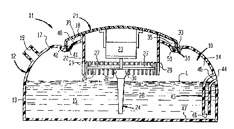
FIG. 1 is an elevational view of a humidifier according to the invention; and
FIG. 2 is a transverse cross sectional view of the humidifier shown in FIG. 1.
DESCRIPTION OF THE PREFERRED EMBODIMENT
A humidifier 11 includes a base enclosure 12 forming a discharge chamber 10
with a lower portion 13 that defines a reservoir for liquid 15. A cover
portion 17 of the
base enclosure 12 forms an upper portion 14 of the chamber 10 and defines a
circular
opening 18 disposed above the reservoir 14 and a discharge orifice 19
communicating
therewith. Also included in the humidifier 11 is a humidification unit 21
supported by
the upper wall portion 17 of the base enclosure 12. The humidification unit 21
includes
a cylindrical housing 22 defining an inlet chamber 20, a motor 23 retained
within the
2

CA 02089453 2001-04-23
housing 22 and an impeller unit 24 rotatably coupled with the motor 23.
Forming the
impeller unit 24 is a plate 26 defining upwardly directed vanes 27 and a
hollow
inverted cone 28 projecting downwardly into the reservoir 14 within the base
enclosure
12. A diffuser assembly includes a plurality of circumferentially spaced apart
spokes 29
formed on the bottom of the housing 22 and disposed above and radially outside
the
hollow cone 28. Defined in an upper portion of the cone 28 are a plurality of
apertures
30.
An annular joint 31 between the humidification unit 21 and the upper wall
portion 17 permits separation thereof. Providing a vapor seal for the annular
joint 31 is
a sealing mechanism including an annular channel 33 defined by the upper wall
portion
17 and surrounding the opening 18 therein and an annular skirt 35 formed at an
outer
lower periphery of the humidification unit 21 and projecting downwardly into
the
annular channel 33. A bottom edge 41 of the annular skirt 35 forms a supported
surface
of the humidification unit 21 that is supported by a support surface 42 of the
base
enclosure 12 formed by the bottom of the annular channel 33. Sloping toward
the
channel 33 is an inner surface portion 38 of the unit 21 disposed within the
joint 31 and
communicating with the discharge chamber 10 via a passage 39 between the
opening
18 and the housing 22. Similarly sloping toward the channel 33 is an interior
surface
portion 40 of the base enclosure 12 also communicating with the reservoir via
the
passage 39.
Also formed in the upper portion 17 of the base enclosure 12 and in the upper
portion 14 of the chamber 10 is an overflow port 44. A tube 45 extends between
the
overflow port 44 and the lower portion 13 of the chamber 10. One open end 46
of the
tube 45 terminates at the overflow port 44 while another open end 48 of the
tube 45
terminates closely adjacent to a bottom 47 of the chamber 10.
OPERATION
Prior to operation of the humidifier 11, the reservoir 13 is filled with
liquid 15
and the annular channel 33 is filled with water 51 to form a liquid seal
between the
annular skirt 35 and the annular channel 33. Subsequent electrical
energization of the
motor 23 produces rotation of the impeller 24. The rotating cone 28 produces
within the
-,

CA 02089453 2001-04-23
reservoir 13 centrifugal forces that force water upwardly for discharge
through the
apertures 30. Water ejected through the apertures 30 is directed against the
spokes 29 of
the diffuser assembly 26 which breaks the water into fine mist droplets.
Because of a
positive pressure produced in the chamber 10 by the air moving vanes 27, the
mist
droplets produced by the humidification unit 21 are discharged through the
discharge
orifice 19 into the surrounding environment. However, discharge of droplets
through
the annular joint 31 between the humidification unit 21 and the base enclosure
12 is
prevented by the water seal 51 created between the annular channel 33 and the
annular
skirt 35. Consequently, an undesirable accumulation of condensation on the
outer
surfaces of the humidification unit 21 and the base enclosure 12 is prevented.
During
operation of the humidifier 11, a seal is maintained by liquid that passes
from the
discharge chamber 10 through the passage 39, collects on the inner surface
portion 38
of the unit 21 and the interior surface portion 40 of the base enclosure 12
and then drips
into the annular channel 33.
The overflow port 44 establishes a maximum liquid level L within the chamber
by draining any liquid above that level caused either by overfilling of the
enclosure
12 or liquid movement produced by the impeller 24. Thus, undesirable
submersion of
the electrical motor 23 is prevented. In addition, undesirable discharge
through the
overflow port 44 of liquid dispersed by the impeller 24 is prevented by the
tube 45
which extends into the liquid 15 to create a liquid seal for the overflow port
44.
Obviously, many modifications and variations of the present invention are
possible in light of the above teachings. It is to be understood, therefore,
that the
invention can be practiced otherwise than as specifically described.
4

Representative Drawing
A single figure which represents the drawing illustrating the invention.
Administrative Status

2024-08-01:As part of the Next Generation Patents (NGP) transition, the Canadian Patents Database (CPD) now contains a more detailed Event History, which replicates the Event Log of our new back-office solution.

Please note that "Inactive:" events refers to events no longer in use in our new back-office solution.

For a clearer understanding of the status of the application/patent presented on this page, the site Disclaimer , as well as the definitions for Patent , Event History , Maintenance Fee  and Payment History  should be consulted.

Event History

Description Date
Inactive: IPC assigned 2021-11-09
Inactive: IPC expired 2011-01-01
Inactive: IPC removed 2010-12-31
Inactive: IPC from MCD 2006-03-11
Time Limit for Reversal Expired 2004-02-12
Letter Sent 2003-02-12
Grant by Issuance 2002-02-05
Inactive: Cover page published 2002-02-04
Inactive: Final fee received 2001-11-07
Pre-grant 2001-11-07
Letter Sent 2001-05-17
Notice of Allowance is Issued 2001-05-17
Amendment Received - Voluntary Amendment 2001-04-23
Inactive: Office letter 2001-03-05
Inactive: Approved for allowance (AFA) 2001-02-12
Inactive: Application prosecuted on TS as of Log entry date 1999-04-12
Letter Sent 1999-04-12
Inactive: Status info is complete as of Log entry date 1999-04-12
All Requirements for Examination Determined Compliant 1999-03-29
Request for Examination Requirements Determined Compliant 1999-03-29
Letter Sent 1998-02-02
Inactive: Multiple transfers 1997-11-19
Application Published (Open to Public Inspection) 1993-10-16

Abandonment History

There is no abandonment history.

Maintenance Fee

The last payment was received on 2001-12-27

Note : If the full payment has not been received on or before the date indicated, a further fee may be required which may be one of the following

  • the reinstatement fee;
  • the late payment fee; or
  • additional fee to reverse deemed expiry.

Patent fees are adjusted on the 1st of January every year. The amounts above are the current amounts if received by December 31 of the current year.
Please refer to the CIPO Patent Fees web page to see all current fee amounts.

Fee History

Fee Type Anniversary Year Due Date Paid Date
Registration of a document 1997-11-19
MF (application, 5th anniv.) - standard 05 1998-02-12 1997-12-24
MF (application, 6th anniv.) - standard 06 1999-02-12 1999-01-07
Request for examination - standard 1999-03-29
MF (application, 7th anniv.) - standard 07 2000-02-14 2000-01-21
MF (application, 8th anniv.) - standard 08 2001-02-12 2000-12-21
Final fee - standard 2001-11-07
MF (application, 9th anniv.) - standard 09 2002-02-12 2001-12-27
Owners on Record

Note: Records showing the ownership history in alphabetical order.

Current Owners on Record
HONEYWELL CONSUMER PRODUCTS, INC.
Past Owners on Record
FRANK MARINO
Past Owners that do not appear in the "Owners on Record" listing will appear in other documentation within the application.
Documents

To view selected files, please enter reCAPTCHA code :


To view images, click a link in the Document Description column. To download the documents, select one or more checkboxes in the first column and then click the "Download Selected in PDF format (Zip Archive)" or the "Download Selected as Single PDF" button.

List of published and non-published patent-specific documents on the CPD .

If you have any difficulty accessing content, you can call the Client Service Centre at 1-866-997-1936 or send them an e-mail at CIPO Client Service Centre.


Document
Description 
Date
(yyyy-mm-dd) 
Number of pages   Size of Image (KB) 
Description 1993-12-12 6 226
Claims 1993-12-12 4 132
Abstract 1993-12-12 1 22
Drawings 1993-12-12 1 31
Description 2001-04-22 4 196
Claims 2001-04-22 4 119
Abstract 2001-04-22 1 18
Representative drawing 1999-06-20 1 20
Representative drawing 2002-01-15 1 23
Acknowledgement of Request for Examination 1999-04-11 1 178
Commissioner's Notice - Application Found Allowable 2001-05-16 1 164
Maintenance Fee Notice 2003-03-11 1 174
Fees 1997-12-23 1 41
Fees 2000-01-20 1 38
Fees 2000-12-20 1 37
Fees 1999-01-06 1 42
Correspondence 2001-11-06 1 37
Correspondence 2000-10-22 1 13
Fees 2001-12-26 1 48
Fees 1997-01-14 1 47
Fees 1996-01-30 1 43
Fees 1995-01-25 1 46